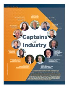
The NIA staff interviewed the Presidents and CEOs of allied associations to bring our readers a better perspective on how 2020 impacted the different sectors of the construction industry and what is predicted for the remainder of 2021.
We offer our thanks to the industry leaders pictured here for taking the time to share their insights and expertise. Please note that NIA is a non-partisan organization, and we do not pledge support for any political party or candidate. While these leaders are welcome to share their organizations’ viewpoint and goals, these do not represent the positions of NIA.
Paula Glover, Alliance to Save Energy
The Alliance to Save Energy is a more than 40-year-old organization based in Washington, DC, that advocates for an “efficiency first” approach to the challenges facing our energy system today, including energy affordability, climate change, and creating accessible job opportunities. The Alliance to Save Energy’s mission is to improve energy productivity by:
Leading bipartisan initiatives that drive technological innovation and energy efficiency across all sectors of the economy, through policy advocacy, education, communications, and research.
Convening and engaging in diverse public private partnerships, collaborative efforts, and strategic alliances to optimize resources and expand our sphere of influence.
Tell our readers a little about yourself.
I started as the Alliance to Save Energy’s President in January 2021. Before starting as President, I had previously served on the Alliance’s Board, and was President and CEO of the American Association of Blacks in Energy for 7 years.
Tell us about the Alliance’s membership.
One of the reasons I was really excited to come to the Alliance was its stakeholder-driven approach: We work with our more than 100 Associate organizations—from Fortune 500 companies to national labs and environmental and consumer advocacy groups—to advocate for efficiency. This diverse membership of organizations that truly believe in the power of efficiency to build a more clean, resilient, and equitable energy system is what makes us so strong.
Looking back, what was 2020 like for your sector?
There were really two sides of the coin last year for efficiency. On the one hand, it was a devastating year: More than 300,000 energy-efficiency workers were still out of a job at the end of the year due to the effects of COVID-19. Energy efficiency is often in-person, capital-intensive work—think commercial building retrofits or home energy audits—which is exactly the kind of work most impacted by the pandemic. We also saw some evidence that, due to scaled-back budgets and cheaper energy prices, energy-efficiency investment may be down in the coming years, despite proof that this is exactly the time to be scaling up to create economic activity and address the climate crisis. We did see energy consumption drop sharply in 2020, obviously for the wrong reasons—i.e., due to people traveling less and just generally reducing their activity—but actually in many cases we did not see it drop as much as you would think. We had buildings across the country sitting mostly empty yet still using the same or comparable amounts of energy, which points to a real problem in how we manage energy use in our buildings.
Then there is the other side of the coin. We have seen increased recognition of the role efficiency can play as the energy system transforms: It is being included in high-level policy discussions around Capitol Hill, the capabilities afforded by new technologies are growing fast, and there is a lot of hope that efficiency will be included in recovery measures—something we call “Building Back Brighter.” So, while it was a tough year for our industry, we are hopeful that—with the right policies in place—efficiency will come back stronger than ever. But we have a lot of work ahead of us.
What are your near-term predictions for your sector?
It is unfortunately pretty clear that jobs are not coming back on their own, at least not at any level of sustainable growth. Efficiency saw just a half-percent gain in employment in December 2020. At that rate, it would take years to regain the jobs lost in the last year. Congressional action is needed to stimulate full recovery. Included in those conversations needs to be not just achieving growth but achieving equitable growth—reaching the communities that need these opportunities the most and improving diversity and inclusion in the sector.
Please expand on the impact of 2020 and your outlook for 2021 and beyond.
Everyone’s number 1 concern last year was alleviating some of the economic suffering that COVID-19 caused, so we spent a lot of time in 2020 working with all our stakeholders and members to design economic recovery plans that leverage the power of efficiency to create jobs and economic activity, save consumers money, and reduce climate-warming emissions. We came away with four top-priority areas that we are now pushing to get through Congress, and support and input from our members was absolutely critical throughout the process.
One exciting initiative that we built out in 2020 was our Active Efficiency Collaborative. Active Efficiency takes a digitalized, comprehensive approach to energy management, including both passive and dynamic solutions. Our Collaborative members see an opportunity to really bring together all these different aspects of efficiency—from building envelope and mechanical systems improvements like insulation to smart thermostats that optimize temperature settings and time-dependent approaches like utility demand response programs—and make them all work in cohesion to maximize our energy savings. 2020 was the first full year of the Collaborative, and we made some important headway that will be built upon this year.
One thing we still must work to resolve is that, like nearly every sector, we have a lot of work to do around equity. To provide a more specific example, energy-efficiency upgrades are something that requires up-front cost. Maybe you know that if you weatherize your home, add higher quality insulation, etc., you will save hundreds of dollars a year on your energy bills and easily recapture the up-front cost of those upgrades; but if you do not have the money to start with, you do not even have that choice. So that leaves a lot of people who need efficiency the most—people who are facing high energy burdens and maybe even forgoing paying for food or medicine to keep the electricity on—without the opportunity to permanently lower their monthly energy bills with efficiency. That is just one example of a challenge we still need to resolve. One solution is expanding the [Department of Energy’s] Weatherization Assistance Program, which reaches households like those with low- and no-cost upgrades; but even if we are able to do that, it is far from the end of the work that needs to be done. We also need to do more to make sure that historically disadvantaged communities and people of color have more of an opportunity to participate in the energy-efficiency economy. Efficiency employs more than 2 million people in the United States, and the jobs are spread across the country, so we need to do more in training and workforce development to get those jobs into disadvantaged communities. And not just jobs, but entrepreneurial opportunity. Most energy-efficiency businesses are small businesses, and we would like to see more opportunities for minority ownership.
An uphill battle for the efficiency sector is just making clear the role we play in the energy economy. Most people outside this industry do not realize that energy efficiency employs more than 2 million Americans—by far the largest employer in clean energy, and one of the largest employers in energy overall. We sometimes like to say we are a workhorse, not a show horse; but we really should be both, because more Americans should know about the opportunities in this sector for good-paying jobs that also help the planet and help consumers. I think part of that challenge is building a stronger identity among the workforce: we are so varied, including energy service companies, construction, and manufacturing positions. Mechanical insulation workers should know that they are part of the efficiency industry as well!
Looking to the end of 2021, there is much to be excited about this year, but only if we do things right. We are seeing a lot of conversations on Capitol Hill that would start to prioritize efficiency more as the incredible energy solution it is; and by the end of the year, we could have policies in place that spur building retrofits across the country, with subsequent demand in manufacturing for energy-efficient products. You can bet the Alliance is working hard to get bipartisan policies with maximum impact signed into law. I am also encouraged to see many people starting to take equity considerations a whole lot more seriously, because as we spur growth in efficiency, we absolutely need to be prioritizing investment in our disadvantaged communities who for too long have had the most to gain from the cost and emission savings of efficiency but also had the least access to the solutions.
With an optimistic outlook and recognition that it is going to take a whole lot of work to get there, I see efficiency on the up and up at the end of 2021, with us doing a better job of reaching the people who need its benefits the most.
Paula R. Glover started as President of the Alliance to Save Energy (www.ase.org) in January 2021. A dynamic leader with more than 25 years of experience in the energy industry, Glover is the seventh President in the Alliance’s 43-year history. She previously served as President and CEO of the American Association of Blacks in Energy (AABE), a non-profit professional association whose focus is to ensure that African Americans and other minorities have input into the discussions and development of energy policy, regulations, and environmental issues. In that role, she was responsible for managing the national office and providing strategic direction and leadership for the organization. Before that, Glover served as AABE’s Vice President of Operations and as the organization’s Director of Communications.
Glover’s experiences include 15 years in the energy industry for both electric and natural
gas distribution companies. She built a stellar reputation working with state legislators and regulators in her roles as Manager of Government and Regulatory Affairs. She also is a seasoned non-profit professional. Prior to her time at AABE, Glover was Community Awareness Director for the Regional YMCA of Western Connecticut, responsible for the organizations’ marketing, communications, community and government relations, and public relations functions.
In March 2014, Glover was appointed to the National Petroleum Council by U.S. Secretary of Energy, Dr. Ernest Moniz. She is the recipient of the Bring It Home to Hartford Award, the Clarke Watson Chairman’s Cup, the Award of Distinction by the Videographer Awards, and the Platinum Achievement Award from the Cooperative Developmental Energy Program at Fort Valley State University. Glover received her BS in marketing management from the University of Delaware. She is a 2003 graduate of Leadership New Haven and has contributed to an article on work-life balance in Take Pride magazine.
Michael D. Bellaman, Associated Builders and Contractors (ABC)
ABC’s mission is the advancement of the merit shop construction philosophy, which encourages a fair and open competition approach that awards contracts based solely on merit, regardless of labor affiliation.
ABC’s long-term strategic goals are to:
- Establish ABC members as the world-class standard for health, safety, and the environment;
- Increase the political influence of ABC;
- Be the leading force for workforce development and education; and
- Continuously grow and deliver value to a diverse and committed membership.
Tell our readers a little about yourself.
As President and CEO of ABC, I work to leverage the merit shop philosophy to help our members develop people; win work; and deliver that work safely, ethically, and profitably for the betterment of the communities in which they work. Before coming to ABC, I worked in the construction industry for more than 20 years, so the issues and concerns ABC focuses its efforts on resonate with me.
Tell us about ABC’s membership.
ABC was founded in 1950 and is a national trade association representing more than 21,000 members from 69 chapters across the United States.
Looking back, what was 2020 like for your sector?
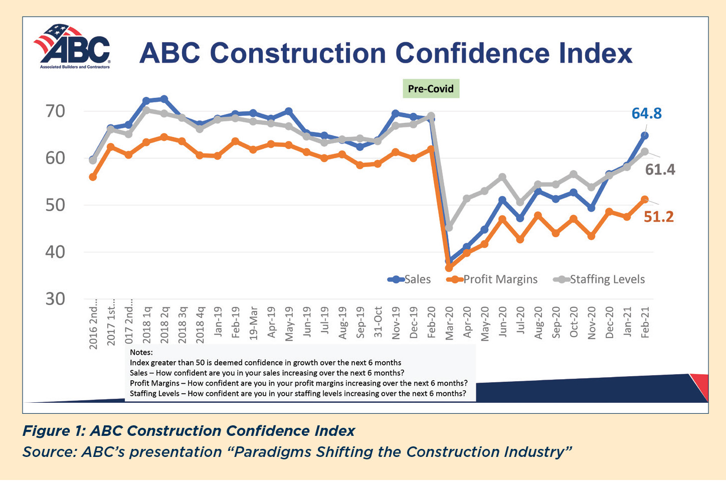
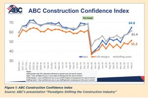
In January 2020, we were seeing record growth trends—high confidence in sales, profits, and staffing; then the pandemic hit, and everything just fell through the floor. In February 2020, ABC’s Construction Confidence Index (CCI), which measures construction contractors’ expectations for sales, profit margins, and staffing in the next 6 months, ranged between 60 and 70 (out of 100) for all 3 factors. Anything above 50 is considered to indicate anticipated growth in the near term, and we had not dipped below about 60 to 65 in any of the indicators since early 2017. In March, everything crashed—we saw numbers below 50, with profits and sales rated below 40, reflecting the immediate effect of everything shutting down. And when projects shut down, the industry lost nearly a million jobs in March–April 2020.
Fortunately, things turned around fairly quickly, as our industry was identified as essential across much of the United States. By mid-June, job sites were open again in all states, and it was off to the races. The construction industry (residential and commercial) received the third-largest share of Payment Protection Plan (PPP) dollars in April, totaling more than $65 billion. Now, many of the economic markers are trending at or close to pre-COVID-19 levels, with some segments showing real growth.
Outside market conditions, we should not overlook many positive developments made over the last year in terms of advances in safety, new uses of technology, and the ways our industry quickly adapted to conditions to keep working.
What are your near-term predictions for your sector?
Our members feel good about the future in the next 6 months, in part because projects under contract when the pandemic hit were more often put on hold than canceled. This
is reflected in the Construction Backlog Indicator (CBI), which has shown a big jump over the past few months. After bottoming out in November at just over 7 months, February’s report is up to 8.2 months, compared to the pre-pandemic level of 8.9 months. The question is, when will the vaccines move owners and projects into a go/no go decision?
We also have seen CCI numbers rise since the bottom dropped out in March 2020. All 3 indicators are back above 50, with sales in particular approaching pre-pandemic levels (see Figure 1).
Most of the gains have come from residential construction. Non-residential spending is still down 5% year over year. Manufacturing, power, and commercial lost ground, while other non-residential sectors—such as highways and public safety—were up.
What remains to be seen are the impacts of regulatory changes, surging material input costs (particularly iron and steel; softwood lumber; prepared asphalt, tar roofing, and siding products; and crude petroleum), and rising interest rates—any or all of which could create a headwind for the industry.
Please expand on the impact of 2020 and your outlook for 2021 and beyond.
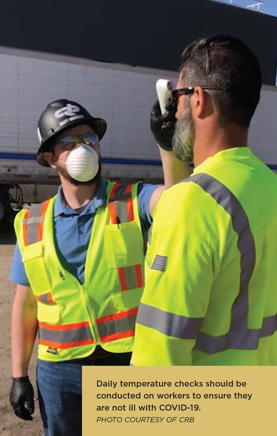
During the past year, our members needed clarity and information. People needed to know what safety protocols were necessary to protect employees on the job, what procedures to follow if someone contracted or was exposed to COVID-19, etc.
Early on, the question was, how could we convince governors across the country that it was safe to build? It helped that the construction industry has a culture of safety—our workforce is used to using personal protective equipment (PPE) and following safety protocols. ABC member companies quickly got creative about how to set up handwashing stations, how to make cloth masks. The industry worked with OSHA to develop safety protocols to prevent transmission and learned what to do if someone got sick. ABC worked with governors around the country to get job sites open again.
Construction firms also rapidly adapted to using innovative tools and technologies to enhance safety, for example:
- Internet of things (IoT) devices to warn of safety occurrences,
- Wearable solutions that improve safety awareness (e.g., sensors that help people keep track of their distance from others),
- Safety documentation,
- Tools to prevent injuries,
- Site sensors, and
- Drones.
These technologies enabled companies to track everyone who entered and exited a job site (useful both for ensuring social distancing and for contact tracing if anyone contracted the virus); ensure the health of employees on job sites; document employee health testing, social distancing data, and overall jobsite conditions; and monitor proper PPE use. Additionally, we saw use of prefabrication and modular construction growing in use. Along with other benefits, moving work into a controlled environment, working consistently at the same location instead of moving around from site to site, provides a level of protection during the pandemic. We see these as long-term trends that are here to stay.
At the same time that we worked to make it safe for people to work together on job sites, we pivoted to holding association meetings virtually and offering webinars, which were tremendously successful. One webinar that had a limit of 1,000 attendees sold out in 10 minutes, which shows you how much people were seeking accurate information. ABC ran webinars almost every day for about 6 months, which was necessary because the guidance changed daily.
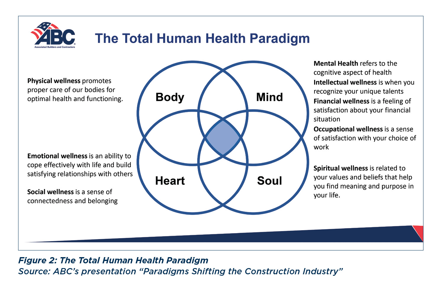
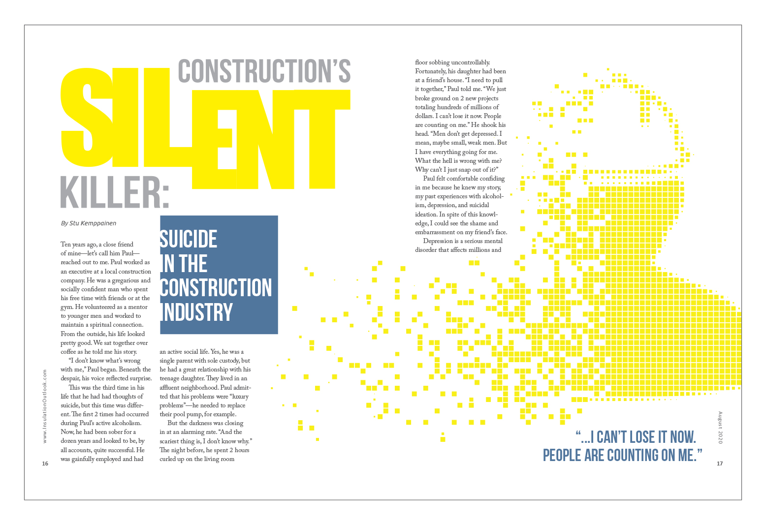
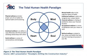
The anxiety over how much was unknown about COVID-19, and how the guidelines kept changing, fed into an area of safety we are really only starting to recognize and address. In our industry, we have always focused on the physical aspects of safety. The pandemic has raised awareness of what we at ABC refer to as the Total Human Health Paradigm (see Figure 2). To give you an idea of why this is important, in 2018, there were 1,008 construction worker fatalities, which comes to a rate of 9.5 per 100,000 workers. That same year, an estimated 5,242 construction workers died by suicide—a staggering rate of 49.4/100,000.
The pandemic is challenging workers’ total health as never before. In addition to fears over losing a job and income, where before they only had to worry about their own safety, construction workers are now afraid of bringing the virus home to their loved ones. Even before the COVID-19 pandemic, seeking help was not necessarily part of the culture. Now, death by suicide is driving a new paradigm shift in safety. ABC is part of the Construction Industry Alliance for Suicide Prevention, a coalition of industry organizations working to reduce suicide risk across the construction industry by equipping companies to better address mental health issues and promote the safety and well-being of construction workers. ABC’s Vice President of Health, Safety, Environment and Workforce Development, Greg Sizemore, serves as Chairman of the alliance’s Board of Trustees, which indicates how important we view this issue as a health and safety priority going forward. Through the alliance and on our website, ABC provides resources for individuals and companies to get help, with the goal of creating a zero-suicide industry.
The construction industry has a lot to offer people looking for a career, and another focus in the coming months and years is recruiting future craft professionals, making it attractive to all, including those in underserved communities; people unsettled from other industries, who may have lost their job during the pandemic and see the value of working in an essential field; degreed and non-degreed individuals looking for a career path; those exiting military service; and more. ABC works with Diversity Resource Groups (DRGs), voluntary associations of people who have common interests that may be related to race/ethnicity, gender, etc., soliciting DRGs’ input on how we can create value for their members—at the individual and company level. This June, we will be holding our seventh annual Diversity and Inclusion Summit, bringing together industry leaders and stakeholders to help promote a more diverse construction industry. We also award ABC’s National Diversity Excellence Awards to recognize members that display exemplary diversity leadership in their company, workforce, supply chain, and community with best-in-class recruitment policies, retention practices, and training and mentoring programs. The goal is to identify, create, and develop a diversity of entry points for those who choose construction as a career. From there, training and skills development—through Department of Labor programs, industry-recognized apprenticeships, competency-based apprenticeships/education, mentoring and on-the-job training, or a multitude of other sources—help people develop a career path (earning while they are learning) and companies optimize return on investment in their workforce development.
The industry also is evolving so that different skills are needed than those of the past. With greater use of technology including virtual reality, 3D printing, unmanned vehicles, IoT, sensors, and telematics, etc. for communication, site monitoring, and inspection, companies will need people with the skills and knowledge to develop, apply, maintain, and use those resources. We are also hearing that more and more ABC members have experienced a cybersecurity attack or attempt, so that is another area of focus to improve upon.
While we are still down 222,000 net jobs since March of last year, the numbers are up in the residential sector, and U.S. Census Bureau and Bureau of Labor Statistics (BLS) data indicate the need for workers is growing. We had 7.83 million people employed in 2020, when 8.15 million were needed. Additional factors that make our industry attractive: hourly wages are up 3.1% over a year ago; and the gender pay gap is minimal in our industry, with women making 99.1% of what men get paid (based on BLS reported data from December). That equality makes sense in an industry that is pay-for-performance based. As I write this, it is Women in Construction Week (March 7 to 13, 2021), and 43% of ABC’s membership report intentionally recruiting women for employment.
People are familiar with all the big construction firms, but 98% of U.S. construction companies employ fewer than 100 people, and those companies are responsible for 63% of all construction projects across the country. Those smaller companies will be key to creating and filling jobs in the near term. At the same time, they can be more vulnerable to some of the challenges to come. What may be underestimated in the positive CCI numbers is the potential impact of new regulations on these businesses—small companies do not have a compliance officer, for example. The industry will need to see what happens with legislation and regulation in a number of key areas: the PRO Act; infrastructure; immigration; National Labor Relations Board actions; and possible reversal of regulations affecting joint employers, independent contractors, and government-mandated project labor agreements.
Paradigms are shifting in the construction industry. ABC will continue to work to provide clarity and information to help its members navigate the changing landscape.
Michael D. Bellaman has served as President and CEO of ABC (www.abc.org) since 2011. Under his leadership, ABC received the Pledge to America’s Workers Presidential Award in 2020 based on its achievements in workforce education and fulfilling its 2018 pledge to recruit and upskill at least 500,000 workers by 2023. Bellaman is dedicated to helping ABC members and the construction industry be world class in safety. He is a co-founder of the Construction Coalition for a Drug- and Alcohol-Free Workplace and has championed a roadmap for companies whose leaders want to transform their safety programs from the ground up through ABC’s industry-revolutionizing STEP Safety Management System. A 1985 graduate of Pennsylvania State University, Bellaman earned a BS in architectural engineering and spent more than 2 decades in the construction industry before joining ABC.
Stephen E. Sandherr, Associated General Contractors of America (AGC)
The Associated General Contractors of America is an organization of qualified construction contractors and industry-related companies dedicated to skill, integrity, and responsibility. Operating in partnership with its chapters, AGC of America provides a full range of services satisfying the needs and concerns of its members, thereby improving the quality of construction and protecting the public interest.
Tell our readers a little about yourself.
A recovering lawyer, I am originally from Harrisburg, Pennsylvania, but moved to DC for law school and have been here basically ever since. When I am not working, I enjoy golfing and (pre-pandemic) traveling with my wife, Cynthia. I also volunteer my time as an honorary board member at the National Building Museum, as well as with other educational and charitable organizations.
Tell us about AGC of America’s membership.
Our 27,000 plus members represent every facet of the commercial construction industry, from general contractors to specialty contractors, service, and suppliers.
Looking back, what was 2020 like for your sector?
While 2020 was an extremely challenging year for the commercial construction industry, it frankly could have been significantly worse. Our members were fortunate in that we were able to successfully advocate to get construction identified as essential by federal officials. This allowed most of our chapters to successfully get construction excluded from the extensive shutdown orders that hobbled so many other sectors last spring. It also helped that our members had a strong tailwind heading into 2020, thanks to a very strong pre-pandemic economy. This meant that many firms spent 2020 working their way through robust backlogs. And while many future projects, particularly those in the private sector, have been delayed or canceled, most of our firms had a relatively good year business wise. The biggest challenge they faced was in making the significant operational changes needed to protect workers from the coronavirus.
What are your near-term predictions for your sector?
In early January, AGC of America and our partners at Sage Construction and Real Estate released the 2021 Construction Hiring and Business Outlook. This annual forecast, which is based in large part on member responses to our annual outlook survey, was particularly downbeat. Members predict that demand for many types of construction—including office, retail, and lodging—will decline. They do not expect demand to return to pre-coronavirus levels for many months to come. And far fewer members plan to expand their headcount compared to prior years.
Please expand on the impact of 2020 and your outlook for 2021 and beyond.
Last year was the “break glass in case of emergency” moment for many members when it came to needing AGC of America, and we more than met that moment. While our advocacy successes were often the most high profile, we were also able to make significant changes to allow members to continue learning, meeting, and connecting in 2020. As a result, while many other associations struggled, we kept our budget balanced; expanded membership; and evolved into an even more nimble, responsive, and relevant association.
We have spent years cultivating strong working relationships with a wide range of government officials—from career bureaucrats to political appointees, legislators, and their staffers. They trust us because we are honest brokers—we tell the truth and do not indulge in hyperbole. This trust and those relationships were key to our ability to successfully make the case that the construction industry should be included in the federal list of essential industries.
Our relationships also helped us make sure construction firms were eligible for federal Paycheck Protection Program (PPP) loans and kept firms from being taxed for those loans. We also are helping make sure those PPP loans are being forgiven in a transparent way, based on the criteria outlined by Congress when it created the program. AGC of America’s relationships also helped us secure billions of dollars in needed new infrastructure investments last year. We also have invested a lot of time and resources in our education and meetings programs, anticipating growing demand for virtual delivery. This was one of the key recommendations to come out of our Centennial Future Focus effort; so while none of us expected the transition to virtual to be so sudden or absolute, we were ready when the world went virtual in March 2020.
Our preparations allowed us to rapidly transition large parts of our educational programming—including the Building Information Modeling and Lean education courses—to virtual delivery. It also allowed us to continue with already-scheduled meetings and conferences, virtually, with the same top-quality content at a time when many other associations were still trying to figure out how to use Zoom.
Last year was unusual, and hopefully unique, in the quantity and severity of challenges it posed. But there is nothing unusual about our ability to deliver success for our members. It just so happened that we had more opportunities, and a greater need, to do that in 2020. The work we do day in and day out enabled us to meet the moments of 2020 and keep America building successfully.
Moving forward, our challenge is to help ensure that the construction industry plays the lead role in helping the American economy recover. While our members are more optimistic about the outlook for 2021 now than they were a few months ago, many challenges remain.
Foremost among those challenges are the significant disruptions to the supply chain for construction materials that are leading to project delays and significant price spikes. That is why we are urging the Biden administration to ease tariffs on key construction components, including lumber and steel, and to take steps to ease shipping delays at our ports and within the trucking industry. Many of our members also report that they continue to have projects canceled or delayed while the private sector waits to see what will happen after the pandemic. That is why we are pushing for broad new federal infrastructure investments. These funds will help improve our infrastructure and keep demand strong for a range of construction services.
More generally, we are working to educate Congress and the Biden administration about the need for measures to support broader economic growth. This includes liability reforms, so that employers who are taking steps to protect their workers from the coronavirus are not subjected to frivolous lawsuits.
At the same time, we are urging Washington officials to avoid taking steps that would undermine future economic growth. Measures like the PRO Act, which could unleash a new era of labor unrest and hurt workers, and efforts to impose new regulations will only negatively impact the industry’s ability to rebuild our country.
We are also focused on making sure AGC of America continues to offer a broad range of virtual, and ultimately, in-person, events and programming so our members can stay on top of rapidly changing business conditions. Our goal is clear: to make sure our members end 2021 on a far more positive note than they started the year.
Stephen Sandherr is the CEO of AGC of America (www.agc.org), having first joined the staff in 1984 as Assistant Director of Collective Bargaining Services. From 1986 to 1989, he served as the association’s Director of Congressional Relations. He practiced law with the firm of Thompson, Mann, and Hutson in Washington, D.C., from 1989 to 1990; and served as Labor and Small Business Counsel for the National Association of Home Builders from 1990 to 1991. He rejoined AGC of America as Executive Director of Congressional Relations in 1991 and was promoted to CEO in 1997.
Currently, as CEO, his role is to maintain relations with AGC of America’s 90 chapters nationwide, coordinate government relations activities, and enhance the organization’s involvement with business coalitions. A Capitol Hill newspaper, The Hill, has listed Sandherr as a top lobbyist for the last 10 years, representing the only commercial construction industry association on the Top Lobbyists of 2009–2019 lists.
He has a BS in political science from the
University of Scranton, where he serves on the Board of Trustees. He earned his law degree
from the Catholic University of America and is a member of the Bar of the District of Columbia. He is an honorary trustee of the National Building Museum in Washington, DC, and has been inducted into the National Academy of Construction.
Gregory L. Sizemore, Construction Users Roundtable (CURT)
Founded in 2000, CURT is an autonomous, not-for-profit organization that strives to produce meaningful changes within the construction industry—promoting overall cost effectiveness; improving the way construction is planned, managed, justified, and executed. CURT provides a national and international forum for the exchange of information, views, practices, and policies of construction users from an array of industries.
Tell our readers a little about yourself.
All told, I have more than 30 years of construction industry and association management experience in my background. In 1989, I started Sizemore & Company LLC, a construction industry association management and staffing firm, and co-founded CURT about 10 years later with the primary goal of enacting broad, effective owner representation and increased owner leadership on construction industry issues to create competitive advantages for owners.
Tell us about CURT’s membership.
CURT members include construction and engineering executives representing major corporations all across the United States and the world. Our members have nearly
$200 billion in capital and maintenance spending power and include major industrial construction owners—such as Procter & Gamble, Marathon, General Motors, Southern Company, Duke Energy, and ExxonMobil construction—as well as contractor associations.
Looking back, what was 2020 like for your sector?
When I kicked off CURT’s 2021 National Conference, our first to be conducted virtually, I stated that in chaos and crisis comes opportunity and creativity. That statement sums up our year. Construction owners had to be creative and nimble as they pivoted to figure out how to cope with the chaos and crisis of the pandemic. We saw a lot of projects not necessarily canceled—which is good news for the industry—but postponed, simply because it did not seem that they could be safely launched or executed in person, as we have always worked for the last hundred years. We simultaneously saw an emphasis on rapid mobilization for projects and on demobilization of projects. The first issue for our members was, can we pivot and rapidly mobilize workforce and contractors and suppliers and service providers? And can we just as rapidly demobilize?
Along with that was the obvious question, how do you cope with this pandemic? How do you reduce your liability exposure on a job site where you have multiple contractors and suppliers coming and going, with a lot of physical exposure? It took time for companies to figure out their own approach, at the same time asking what the industry best practices were: How frequently are we sanitizing? What’s our mask policy? How do you accomplish distancing when you have crews that are in each other’s face all day, every day? And what do you do if one person in a crew tests positive, or if a family member of someone on a crew gets sick? Does everybody go into quarantine for 2 weeks? What does that do to the schedule and efficiency of the project? The early chaotic experience was explosive. Nobody knew what to do, and that uncertainty about how to do projects caused many to be postponed.
One surprise for owners was how well the market did. There was a lot of speculation about a year ago that the bottom would fall out, and that was not the case. That likely had a lot to do with why projects were postponed rather than canceled.
What are your near-term predictions for your sector?
CURT represents a multitude of sectors: consumer non-durables; oil and gas; Big Pharma; automotive; energy; the U.S. Government (the State Department and U.S. Army Corps of Engineers); and, more recently, high tech, as companies like Google and Amazon build huge data centers. Some sectors are improving at a tremendous rate, while others face more challenges.
I think there is a lot of pent-up demand. With an end to COVID-19 in sight and a good quarter into 2021, there is eager anticipation in the marketplace for goods and services. People are going to be out moving again, traveling, etc., and that will generate demand. So, the outlook for our members is positive, if we can avoid the negative impacts of inflation. Economist Anirban Basu, Chairman and CEO of Sage Policy Group, predicts a “W” type of economic recovery where we will see some volatility, and I can see there being dips and flows.
The big challenge is that as Congress puts money into the economy, there is concern over the impact that indebtedness and inflation will have, which is still unknown. But short term, over the next 12 to 18 months, the outlook is looking very positive for all sectors.
Please expand on the impact of 2020 and your outlook for 2021 and beyond.
One question we are facing now is, what will the stay-at-home policies do to worldwide demand longer term, whether we are talking about cars, shampoo, or paper towels. The consumer non-durable products market exploded last year, while others—oil and gas, for example—faced a real challenge. On the one hand, we are seeing skyrocketing capital portfolios. Consumer non-durables are experiencing amazing growth in stock value, and one of our pharmaceutical company member’s capital portfolio budget experienced a fourfold increase. At the same time, there are reasons to be cautious about the level of optimism. There is concern in the commercial sector, for example. Offices have been abandoned, and there is a lot of empty space for rent. Many of the restaurants near these buildings have closed. While employment numbers have been strong, many jobs have been lost.
It will be interesting to see what changes result from some of these challenges—for example, empty retail space that formerly housed anchor stores in malls is being converted into warehouse space for products purchased online. This type of renovation and repurposing may offer opportunities for construction contractors going forward.
Operationally, it was interesting to see so many in the industry discover web conferencing software and realize they could save millions of dollars a month on travel and lodging (T&L) expenses, as well as lost time and the productivity implications from travel. Think of a large company that typically had, prepandemic, 5,000 rental cars on the road around the world on any given day, throughout the year. Along with those rental cars, the company is paying for hotel rooms, meals, taxis and other transportation, airplane tickets. You can imagine how much that company is saving on T&L having its people stay home. It also lowers risk—what if someone got sick on travel? At the same time, senior executives are seeing stock prices go up, projects are still getting done, so technology is being embraced as a way to do business.
Technology also has elevated in importance in terms of project execution and productivity improvement. Of all the CEO turnover each year, 25% is due to big capital projects gone bad. Owners and high-level decision makers are keen on anything that can improve safety, save time, and improve productivity. At the same time, we are seeing a shift in focus that is affecting which projects get the green light. About 5 years ago, owners were interested in delivering a successful project, which was defined as on time, on budget, and great safety performance. The project was the focus. What we have seen recently is that owners are looking for the business justification for the project: What does this do for the business? Why is this project needed? How can we deliver projects that focus on business needs versus that one individual project? The narrative is shifting from project excellence to business excellence. Decision makers are asking, what does this do for the shareholder? How does this project meet business objectives over the long term? This is an area where the insulation industry can really make a difference. Those who own the capital portfolios—CEOs, etc.—will never talk the language of building information modeling, LEAN, front-end planning, advance work packaging, etc., so we have to learn to speak theirs. If you can sell the value of insulation over time, all the system efficiencies and money saved, the benefits to the environment—those benefits that make good business sense and translate into value for the shareholders—that will make a real difference. Insulation contractors may not be able to reach the owner directly, necessarily, but they can give the general contractors (GCs) something to work with and sell. The GCs are typically making the decision, so sell them on how the insulation product or application will make a difference.
Of course, once the “go” decision is made, the projects have to be safe and well managed, and work has to be inspected for quality assurance. The pandemic experience has changed the way owners do projects. We are using technology in new ways not just for communication but for project management and safety—e.g., devices that geotag workers and report hazards to them, or measure distance from coworkers. GoPro cameras, laptops, and tablets are now all becoming a regular part of a contractor journeyman’s toolbox, no longer just held by foremen and superintendents. Owners are willing to equip workers and are calling for improved, quantified productivity improvement and assessment tools in the field, from the journeyman on up.
The increased, innovative use of technology is going to provide an opportunity in terms of more high-tech training. It also may affect recruiting in the future, as we may see greater understanding of math and science as a prerequisite for trade workers. The industry is going to demand that its workers—from apprentices on up through journeyman—be much more technically savvy and capable than they may have been in the past.
Although new applications and devices emerge constantly, we are seeing that as technology become more and more mainstream in our daily lives, workers are more adaptable and comfortable using it. We saw this in how well people adapted to working remotely. Young professionals—YPs—in particular came to work with experience and familiarity with using technology.
Along with new technology, data is becoming increasingly important. The demand for data is growing, along with an expressed need for objective decision making based on data. As our ability to gather data on productivity, advanced work planning, safety improvements, how we prequalify contractors, etc. grows, we also have the capability to assimilate and understand it. Decision making is going to be more data centric than ever before, so the contractor that can continue to improve productivity in the field, improve safety performance, and embraces any new technological advancement—both in material and in operations—will be in a strong position.
Another area the industry is in high gear over is modular construction and pre-assembly. That has so much value because it addresses the workforce problem, logistics, efficiencies, productivity, safety—it just has it all. The challenge for our members is that in the industrial sector, each project is different.
Outside project performance, there is a real issue in our industry with mental health awareness. The COVID-19 crisis has not only made it more prominent of a problem but fortunately also made it more prominent as an issue to begin to address. The industry culture, with the “alpha dog” mentality, has impeded the willingness to ask for help—
particularly for men. People feel they have to be able to handle everything. Recognizing the issue, last December CURT dedicated an entire issue of our digital magazine, The Voice, to the topic of mental health.1 In addition, we have been running webinars, CURT Connects, and developing resources to help our members: What do you look for? What should owners be requiring contractors to be looking for on the job?
Because the pandemic has changed the way our members do business, it is also changing the way associations provide service. We are challenged in terms of how to deliver training and services. CURT has worked to adapt to our member needs. CURT Connects is a tool to provide that interaction. It is an opportunity for our members to meet about a particular subject—it could be business related or it could just be a topic of interest like sports—with no agenda. The point is to give people an opportunity to get together (virtually) to chat and hang out. We all have three things to offer each other: our experiences, perspectives/what have we learned, and what resources we use to do our job or get through the day. CURT Connects offers our members a venue for informal, peer-to-peer learning—what do I have in my toolbox that may also work for you—that can also wander off topic, providing that social interaction we all need.
Our industry is ripe for change as we look for new ways to improve efficiency, and associations like CURT and NIA can help drive innovation. One way we can do this is by forming strategic alliances to share ideas and best practices. There is high demand for creativity as people look beyond business-as-usual solutions to ask “what if?” in the quest for improved efficiency, productivity improvement, improved supplies, new techniques—bona fide cost savers. We need to explore the “what if” opportunities—those ideas that become “if onlys” if we fail to capture them.
Reference
1. The Voice magazine, Issue 4, 2020, available online at http://flip.matrixgroupinc.net/curt/2020/issue04/#page=18
Gregory L. Sizemore is Executive Vice President of CURT (www.curt.org), the premiere Owners’ organization, representing nearly $200 billion in capital and maintenance spending power. He brings more than 30 years of construction industry and association management experience to his role. In 1989, Sizemore started Sizemore & Company, LLC, a construction industry association management and staffing firm. Some of Sizemore & Company, LLC’s client organizations include: COATS, The South Georgia Construction & Maintenance Council, and The Appalachian Construction Users Council. Additionally, Sizemore serves on various industry and civic boards including the University of Cincinnati’s Industrial Advisory Council, the Dean’s Advisory Board at the Northern Kentucky University Chase College of Law, and the West Virginia Construction Coalition Conference. Sizemore also teaches construction law and leadership and decision-making classes as an adjunct professor at the University of Cincinnati.
Sizemore is a frequent guest speaker at industry events, where he represents “the voice of the owner to the construction industry.” He holds a BS in economics and a MS in industrial and labor relations from the University of Cincinnati. He earned his JD from The Northern Kentucky University College of Law and is a licensed attorney in the State of Ohio. He and his wife, Cynthia, live in Cincinnati, Ohio.
David Terry, National Association of State Energy Officials (NASEO)
Formed by the states in 1986, NASEO is the only national non-profit association representing the governor-designated State Energy Directors and their over 3,000 professional staff from each of the 56 U.S. states, territories, and the District of Columbia. Our primary role is to share best practices in energy policies and programs among the states. We also serve as an exchange point for the private sector to provide input and expertise to the states as they consider energy actions. And, we represent the State Energy Offices’ views on virtually all energy issues before Congress, the Administration, and federal agencies. NASEO facilitates peer learning among State Energy Officials, serves as a resource for and about state energy offices, and advocates the interests of the State Energy Offices to Congress and federal agencies.
Tell our readers a little about yourself.
As Executive Director of NASEO, I lead policy actions and programs in support of the 56 governor-designated energy directors and their offices across the 56 states, territories, and the District of Columbia. I have 25 years of experience in the energy sector, have testified before Congressional Committees, participated in White House Energy Roundtables, informed governors’ energy policy actions, and led state delegations on international energy missions.
Tell us about NASEO’s membership.
NASEO’s State Energy Director members are typically appointed by their governors or serve as appointed cabinet officials. The State Energy Directors have a policy and program role at the state level across almost energy sectors—petroleum, natural gas, solar, wind, electricity, efficiency, etc. Issues that all State Energy Offices have in common include an interest in advancing energy efficiency, job creation, sustainability, and environmental quality. These shared areas of interest include, for example, promoting the wise use of energy resources and accelerating economic development. These issues provide a solid foundation to work with companies and find common ground to meet shared goals.
Looking back, what was 2020 like for your sector?
As each state has experienced the pandemic differently, it is interesting how this crisis unfolded and what energy issues emerged. Since our founding, NASEO has worked with states to improve energy emergency preparedness and response. There is a formal federal structure for energy emergency activities, and we see these issues as a shared federal-state-energy industry responsibility. Most State Energy Offices, NASEO, energy companies, and the federal government had emergency plans in place. However, many of the pandemic elements of these plans were developed over a decade ago, leaving us prepared but facing some new challenges as energy markets have changed during that period. For example, being prepared to answer questions such as: Who gets immunized first in the energy sector in order to keep lights on or fuel flowing, thus allowing mission-critical facilities to run? Who gets protective gear when personal protective equipment (PPE) is difficult to come by? How do we prioritize that at the state level and then coordinate those requests across various energy sectors and with the federal government?
Operationally, we had to think about how to do business differently, whether that is something simple like completing contracts, approvals, and agreements virtually, or something complicated—for example, helping states initiate new energy plans and policies in ways that ensure robust input from citizenry. Because not everybody has access to broadband or video, states needed to consider how to help those residents provide input or obtain services. It prompted questions for our members and in turn required us to identify solutions and share best practices among the states.
And, of course, underlying all those questions is the more critical health threat presented by COVID-19, which is obviously a more serious matter.
We were fortunate that through the hard work of the states, our energy industry partners, and the U.S. Department of Energy, the electricity, natural gas, petroleum, renewable, and efficiency sectors were able to continue to operate. This was in part due to the energy emergency planning I mentioned earlier. I should add, the electricity, natural gas, and petroleum sectors are among the unsung heroes of the pandemic. They did an extraordinary job. Although they typically are not in the news unless there is a problem, at the end of the day, they are responsible for making sure our mission-critical facilities and transportation services have the energy they need to operate.
COVID-19 was a major focal point for the states in 2020, but not the only one. There was a noticeable increase in awareness and resolve to elevate and address the racial, gender, geographic, and other disparities in the U.S. energy economy, inequities which have been exacerbated by the pandemic. In the aftermath of George Floyd’s killing, NASEO’s Board passed a resolution publicly affirming and formalizing our commitment to equity, access, and inclusion. It calls for a number of important actions, under the aegis of NASEO’s Energy Equity Committee, to support the states as they seek to develop energy, resilience, and economic development initiatives for underrepresented communities and low- and moderate-income people. There is a lot of work to do, but I’m proud of NASEO’s growing body of work in workforce development and diversity; and low-income energy efficiency, community solar, and transportation.
What are your near-term predictions for your sector?
We have an extraordinary energy technology revolution underway, not only in the form of low-cost solar and wind-generated electricity, electric vehicles, and energy storage, but also a broad recognition of the value of core energy efficiency activities in buildings—insulation, ventilation, and efficient HVAC. There is also a rapid movement toward building and grid integration, which allows an energy-efficient building’s load to be modulated in response to grid and occupant needs. We see this not only in the energy space for building conditioning, but also for thermal load or products within the building. That can benefit the grid, natural gas system, and building owner. The technologies are here, but we need to be designing energy markets to value and utilize them. These efficiency technologies create jobs and will deliver a more affordable, reliable, and cleaner grid. However, there will be less maintenance done on electric vehicles, meaning lower demand for mechanics. Over time, there will be net job growth and lower energy costs for consumers, but state and federal leaders with the private sector must partner to help transition and support workers in various existing energy-related jobs to take advantage of these new opportunities.
Energy storage prices also continue to plummet, which offers a great opportunity to localize power storage and use. That is another entirely new suite of jobs that was not there following the last major recession in 2008.
All of these new energy areas are seeing increased private investment. The number of energy technology companies supported by investors has risen dramatically and continues to grow as we have seen environmental, social, and governance criteria grow in popularity. Compare this to the situation 10 or 15 years ago, when the interest of private investors in emerging clean energy technologies and core energy efficiency was minimal and not often a topic in corporate board rooms. That not true today, and it is opening even more exciting energy, economic, and climate opportunities in the years ahead.
Please expand on the impact of 2020 and your outlook for 2021 and beyond.
NASEO’s pandemic response plan worked very well. We had anticipated the emergency part: How do we keep the power plant running, whom do we have to communicate with, what lines of communications and protocols need to be provided to the governor so he or she can make appropriate decisions? That all went well, and we are very proud to have supported the states’ work in this area. That said, there were many things we did not anticipate when it was developed. We needed to address operational concerns like critical state roles around energy security and low-income, energy-assistance programs that states operate for individuals trying to pay their energy bills or weatherize their home.
Operationally, we learned how to conduct conferences and meetings virtually. We did not miss a beat in terms of content or quality of information we shared. We made that pivot quickly. Our staff made it look easy—though it was not—and they performed amazingly well under tough circumstances. The only major difference is that our staff meetings feature more pets and babies than they did in the past, which is a welcome change!
On the substantive front, even with the stress and disruption of the pandemic, and the shift to virtual, we did not miss addressing any pressing policy issue in the energy space. We handled the emergency situation with COVID-19 within our own ability and context, and we managed to keep moving forward on multi-state collaboration on electric vehicle infrastructure, building energy codes, grid planning at the local level, energy equity, and resiliency efforts—including coordinating efforts to get FEMA funding for mission-critical facilities. We did not miss any of the things we would have done had we been in normal operating mode; if anything, we might have done more—a testament to our members, staff, and partners.
As we emerge from the economic impacts of COVID-19, we turn to the economic development or redevelopment phase. Some parts of states’ economies have done very well, while other parts—retail and restaurants, for example—have been decimated. How do we help them from an energy perspective as they restart their businesses? Are there efficiency measures government and private-sector partners can offer? Are there sectors that have changed to the point that certain jobs will no longer be available? How can we bring those workers into the energy workforce and train them in different areas that we know are needed?
The Biden administration’s plans to build a modern, sustainable energy infrastructure and equitable, clean energy future include goals that many states share. There may not be agreement on how to reach those goals, but the diversity of opinion can deliver greater innovation and flexible approaches to meet differing needs in every area of the country. The administration’s call for renovating 4 million buildings and 2 million low-income occupied homes is an ambitious and important goal. And we do need to get there. It saves money, minimizes waste, and makes sense. And there will be opportunities there for those in the mechanical insulation industry as NASEO and the states work to improve energy efficiency across all building sectors.
For example, NASEO, on behalf of the states, has been advocating for greater energy efficiency of public and mission-critical facilities such as hospitals, schools, fire and police stations, and water treatment facilities. Efficiency upgrades in those building sectors take pressure off the grid or natural gas system in extreme weather events, and they provide an excellent cost benefit. We support the Open Back Better bill as a great way to tap public-private financing to do efficiency improvements at mission-critical facilities and add federal dollars for resilience improvements. Imagine that you have made efficiency improvements at a hospital and now you need a new, better, longer lasting backup generation system. That backup power system can be made smaller as a result of the efficiency improvements, and it will cost less. This bill would pair those two elements together, and it has a lot of support among our members. Another avenue to get this work accomplished is through the Federal Emergency Management Agency (FEMA) Building Resilient Infrastructure and Communities (BRIC) program, which sets aside a portion of its funds each year for pre-disaster mitigation. NASEO has strongly encouraged FEMA to work with the states in directing some of those funds to mission-critical facility energy efficiency and resiliency improvements. Everyone agrees it is a great idea, but how do you pay for it? One way that you pay for resilience—and offer a great return on that investment for the taxpayer and building operator—is to ensure mechanical insulation and other efficiency improvements are completed first. These are, by definition, cost-effective actions that make the resilience investment better or less expensive. It makes good sense in our homes, businesses, and these important facilities.
Disaster after disaster, we know this “resilient-efficiency” approach has shown value. We know this most recently from the weather events that impacted Texas and many areas of the South-Central and Midwest part of the country. Whether it is winter storms, heat, or hurricanes, the cost to the economy afterward is almost always more than the cost of having done resilient-efficiency and pre-disaster mitigation investment.
NASEO and our members spend a great deal of time on making buildings more energy efficient. With buildings—everything from a water treatment facility to a house—we need to pay more attention to the design element and the integration of technologies, whether it be an inert piece of insulation or a high-end appliance. As good as we have gotten with developing solutions in the laboratory or the testbed, the value is not realized until the technology is integrated and working together with core efficiency elements in the building itself. Analysis emphasizing the lowest cost, highest bang for the buck should be completed and shared widely. When we go out of our way to not favor a particular technology or product, we may miss the importance of doing what is most cost effective first—we should let the data guide those decisions. We should emphasize design, efficiency products, and technologies that have the most lasting, best cost-benefit outcomes. And insulation is one of the products—technologies—that the data supports as a proven winner.
Mechanical insulation reminds me of a very tried, tested, and used technology in electric transmission: the high-temperature, low-sag transmission line. It has been in the market a long time. New installations typically pay for themselves in short order. It is a more reliable product, and more resilient, yet most transmission lines installed today do not include this proven technology. Better informing our energy leaders so that they can ask the question “isn’t there a better and more cost-effective solution?” is part of the answer to this challenge. Mechanical insulation is a bit like that. It is proven to be effective, but people often overlook it to their loss. The onus is on not only the mechanical insulation industry but those of us in the efficiency field to highlight that we have this product and we need to use more of it, even as we look at other new energy technology entrants that understandably capture the imagination of many.
One area we are seeing growth is in recognition of the need to address climate change and the emissions that contribute to it. Leaving aside the resilience component, in terms of reacting to weather events that may result from or be exacerbated by climate change, most states understand the need to address this issue, whether helping their conventional industries continue to operate by addressing carbon or dealing with emissions from buildings, factories, transportation, and the grid.
Over the longer term, the concept of load-shifting in buildings is gaining traction as people consider the ability of buildings to modulate their power and fuel needs based on the efficiency of the building, on-site storage, the operation of equipment, etc. All those factors have to come together in a system, and insulation is a part of that. That is an important place for NIA to engage to make sure that everyone remembers that mechanical insulation is part of that equation. You cannot reduce the operation of the HVAC if the building is not well insulated, and you cannot reduce operation of the steam plant if the pipes are not well insulated.
Related to building-grid integration is resilience. In a recent survey of NASEO members, resilience was second in priority only to electric vehicle infrastructure. As a nation, we are not able to rebuild every school, but we can renovate many of them from an energy perspective. We cannot rebuild every hospital, but we can make existing ones operate better, both from the standpoint of overall energy operation and—thinking about the pandemic—air quality. Resilience issues resonate across the political spectrum in every state. And this is an area where the mechanical insulation industry can definitely contribute to positive change.
Among the changes resulting from the pandemic, we will see a desire for HVAC systems that allow for improved air quality, but there are energy impacts to that decision. Less obvious but just as big a change is that “last mile delivered” for products ordered online. The trips that used to be done by your car and are now done by delivery service, whether it be groceries or another product, include new “last mile” providers. That change is probably enduring, and we do not yet know the impact from an energy use or economic perspective.
In the electric sector, we have seen a change in loads (e.g., on a national basis, greater energy productivity per unit of economic output), with greater differences in some regions. For large commercial office buildings, state-owned buildings, etc., the energy-use profiles have changed greatly due to the pandemic, and they are coming back now, slowly. On the other hand, costs have grown for hospitals and schools from needing to run HVAC equipment more to bring in greater levels of outside air. There is also an energy impact from the vacancy rate in strip malls. All these impacts will need to be assessed over time.
Looking forward, efficiency will continue to be top of mind for NASEO members. Our state members have increased their work on building energy codes to promote energy efficiency, for example. NIA and its members could help the energy sector by expanding education on the role of mechanical insulation in enhancing efficiency and providing resilience—particularly in mission-critical facilities—enabling them to right-size backup generation or a microgrid, for example. If a facility is not well insulated, any backup solution will be bigger and more expensive than necessary. FEMA and the state emergency management agencies are experts at dealing with life-and-health issues, but unless they are brought into the conversation about how insulation contributes to resilience, it is not likely a topic they are aware of in their work. That is definitely an area where your industry has an opportunity to make a big difference.
David Terry is Executive Director of NASEO, having worked with the organization in a variety of capacities since 1996. Terry leads NASEO’s policy actions and programs in support of the 56 governor-designated state and territory energy directors and their offices. He has participated in governor-led policy meetings, testified before U.S. Congressional Committees, and presented at White House and international energy forums. Terry has 25 years of experience working on a range of energy issues for such organizations as the Governors’ Wind and Solar Energy Coalition. Prior to working in the energy area, Terry was Researcher at the National Academy of Sciences and a Statistical Analyst for a consumer products market research firm. He received a BA degree from Bowling Green State University, Bowling Green, Ohio, and he has completed graduate coursework in statistics and marketing at Virginia Tech, Blacksburg, Virginia.
Eric Hoplin, National Association of Wholesaler-Distributors (NAW)
NAW’s mission is to advocate its members’ interests on national public policy issues that affect the entire wholesale distribution industry. NAW assists merchant wholesaler-distributors to be the most efficient channel for bringing goods to market through benchmarking, strategic management information, networking, and high-level conferences. NAW serves as a mechanism, through our Association Executives Council, for the sharing of ideas, programs, and skills among the organization’s member national associations.
Tell our readers a little about yourself.
I am the President and CEO of NAW.
Tell us about NAW’s membership.
NAW represents the 30,000 companies in the wholesale distribution industry, which accounts for one-third of America’s GDP. NAW-affiliated companies are a constituency at the core of our economy—the link in the marketing chain between manufacturers and retailers and commercial, institutional, and governmental end users. Industry firms vary widely in size, employ more than 5.9 million American workers, and account
for $6.01 trillion in annual U.S. economic activity.
Looking back, what was 2020 like for your sector?
Think back to this time last year. The entire economy was turned on its head virtually overnight. While most Americans went home to shelter in place, distributors went to work and kept the supply chain moving. Without the hard work and dedication of the men and women in the distribution industry, the supply chain would have collapsed, the American economy would have been in a tailspin, and millions of additional jobs would have been lost. The resiliency of this industry is one of its most impressive traits, and it has been evident throughout the pandemic. From sourcing new products when demand appeared overnight to fast-tracking technology upgrades, the industry rose to the occasion time and time again as conditions changed over the past year.
But what has been most impactful are the endless stories I hear from NAW members about how they are helping people: We moved heaven and earth to help set up temporary hospitals, get personal protective equipment to companies on the brink of closure without it, and deliver products and materials to our customers so they could keep their doors open; and we made donations to help meet the needs of nonprofits and the public in an unprecedented environment. Perhaps most importantly, now we are helping to distribute the vaccines that will eradicate this pandemic. It has been a difficult year to be sure, but this industry was there for the country when it needed us most, and we are proud of that.
What are your near-term predictions for your sector?
The wholesale distribution industry is going to help lead the economy back to recovery, and the construction and insulation industry will be at the core of that growth. Despite the economic downturn, Americans’ savings have swelled over the past year. Those
savings indicate pent-up demand, which—when combined with the massive capital infusions the government continues to pump into the economy—point to rapid growth this quarter and beyond. When you couple that with the lifesaving work our industry is doing to help distribute and administer the COVID-19 vaccines, we expect the trend of the economy moving back to normal patterns to accelerate, which will only serve to bolster and extend that growth.
While growth and a return to a new normal are good things, they both present massive supply challenges across material, products, and labor, which our members are moving rapidly to address the best they can in order to meet the needs of their customers.
Please expand on the impact of 2020 and your outlook for 2021 and beyond.
In terms of surprises from the last year, I do not think anyone can be surprised by the resiliency of the distribution industry, but I am always amazed by the attitude of the men and women who keep the supply chain moving. Despite all the difficulties associated with operating a business during a pandemic that every sector faced, wholesaler-distributors spent the past year moving the materials and goods people need to every corner of the country—undertaking heroic efforts to help people stay safe and keep our economy moving. I view each of them as heroes—America should view them as heroes—but our wholesaler-distributors just look at it as doing their jobs.
We have heard from many members that they do not know what they would have done without the resources NAW provided every day. At the outset of the pandemic, our industry was not initially deemed essential by the government and nearly had to shut down. NAW quickly intervened directly with Vice President Pence and the administration, which gave us the essential designation that allowed us to keep our doors open. Since then, NAW’s incredible government relations team has provided hundreds of critical updates throughout the pandemic, helping businesses interpret rules and regulations and pointing them to resources to help them keep their businesses operating safely. In addition, our membership programs provided an opportunity for wholesaler-distributor leaders to share best practices and hear about cutting-edge innovations in a rapidly changing, unprecedented environment, helping them adapt their businesses.
The rapid adoption of virtual tools such as Zoom has had a dramatic impact for NAW, as we are now able to reach far more members on a regular basis, engage them with their peers and leading experts, and help them confront the challenges they face and seize the opportunities ahead. We transformed our annual meeting into the NAW Digital Summit and saw record attendance and participation. The response from members was off the charts, with several noting in post-event surveys that it was hands down the best virtual event they attended throughout the entire pandemic. We also moved our signature roundtables and peer exchanges to virtual formats, which our members reported as being vital as they helped each other by sharing best practices and lessons learned as they adapted to the ever-changing business environment throughout the year. We plan to build on the success of engaging our members virtually in the years ahead, offering meetings in person for those who want to network and engage in person, as well as virtual and hybrid options to reach those who prefer not to travel.
Over the past year, many distributors developed new and innovative ideas and creative solutions to serve their communities and customers amid these unprecedented times, while at the same time keeping their employees safe and their doors open. A good example of this is a NAW member company that distributes building products. When the pandemic hit, they immediately launched a campaign encouraging their customers to buy online as a safe way of purchasing. Soon after, they set up kiosks to allow customers to ask questions and place orders at branches and drive-through lanes with self-service checkouts. They also put orders into lockers and behind fenced-in areas with digital security for 24/7 pickup. Whether this member and others maintain drive-through lanes remains to be seen, but distributors should not expect to go back to “normal” once we move past the pandemic. Many of our customers have become accustomed to low-touch, efficient, and often digital engagement with their distributors. Customer expectations have changed, and distributors will have to evolve how they serve their customers to succeed in the post-pandemic world.
Looking forward, I think the vaccines give all of us hope that after a year of battling this pandemic, which has affected so many facets of our lives, there is light at the end of the tunnel and we will soon get our lives back on track. I certainly share that hope.
NAW members have donated hundreds of thousands of medical-grade gloves, thousands of gallons of sanitizer, masks, medical waste bins, and more. As for NAW, we are working with the National Football League to partner with teams such as the Detroit Lions and the Pittsburgh Steelers to get them the supplies needed to stand up Federal Emergency Management Agency-supported mass vaccination sites. We are also pushing the government to expand distribution of the vaccine to health-care providers through our network, which reaches 500,000 hospitals, clinics, pharmacies, dentists, community care centers, and nursing homes. People trust their health-care provider and are more likely to take the vaccine if it is suggested by them. The distribution industry is poised to get more of the vaccine in the hands of medical professionals, just as we distribute the flu vaccine and other medicines every day to every corner of the country.
Eric Hoplin is President and CEO of NAW (www.naw.org) as well as President of the NAW Institute for Distribution Excellence, President of the NAW Service Corporation, and Treasurer of the NAW Political Action Committee. A seasoned executive and communicator who has worked at the highest levels of government and business, Hoplin was previously Head of External Relations for Wells Fargo, where he led a team focused on improving the company’s reputation and advancing pro-growth policy objectives in concert with third-party organizations across the political spectrum. Before joining Wells Fargo, Hoplin served as Executive Director at the Financial Services Roundtable (now BPI), a trade association representing the CEOs of the nation’s largest financial services companies. Prior to that, he worked in management consulting at Booz Allen Hamilton, helping senior leaders across the government solve their most vexing challenges. Earlier in his career, Hoplin worked in politics, supporting many congressional, gubernatorial, and Presidential campaigns. He also is a leader in the charitable community, where he serves on the Boards of the Trust for the National Mall and the Reagan Ranch. A prolific fundraiser, he has raised millions of dollars for charitable organizations and political candidates.
A Minnesota native, Hoplin holds a Master of International Affairs from Columbia University, an MBA from Augsburg College, a BA in political science and communications from St. Olaf College, and a certificate in change management from Georgetown University McDonough School of Business. He lives outside of Washington, DC, with his wife, Nicole, and their three boys.

Lakisha Ann Woods, National Institute of Building Sciences (NIBS)
NIBS was established by Congress in 1974 and is an authoritative voice that supports advances in building science and technology to improve the built environment. We are a 501(c)(3) non-profit, non-governmental organization that works with legislators, regulatory agencies, and officials within the construction industry, aiming to engage and convene all parties and seek consensus solutions to mutual problems of concern. Our mission: To serve the public interest by advancing building science and technology to improve the built environment.
Tell our readers a little about yourself.
As President and CEO of NIBS, I am responsible for leading the organization’s dedicated team of professionals; enhancing its value and visibility; and growing relationships with its members, clients, public agencies, and partners. I have enjoyed the opportunity to build strong relationships with various stakeholders and working with our team to create programs and services that meet the needs of the industry. In addition, I have focused on showcasing the important research and standards that our organization is working on and building our brand around the world.
Tell us about NIBS’ membership.
Members come from all categories of the built environment, including individuals
from the building industry, public interest representatives or groups, students, and organizations. Individual or organizational membership is open to any person employed by, interested in, or associated with building construction, labor organizations, home builders, housing management, building or construction contractors; producers, distributors, or manufacturers of building products; trade and professional associations; organizations engaged in real estate, finance, insurance, or research and testing of building products; and technology and code and standards organizations.
Looking back, what was 2020 like for your sector?
2020 was a challenging yet busy year for those working in the built environment, depending on which sector of our membership you ask. While many businesses pivoted to work online, the building industry and its workers were identified as essential. The housing market had a boom, as people chose to move out of cities and into the suburbs. At the same time, our commercial real estate market struggled in a variety of ways. Many infrastructure workers remained critical—namely energy, health care and public health, chemical, government facilities, some manufacturing, water and wastewater, transportation systems, and commercial facilities.
What are your near-term predictions for your sector?
Considering the uncertainty of the various policies in relation to remote work and the pandemic, we must be cautious in our predictions. Our industry represents essential workers and no matter the status of the current pandemic, we will continue to operate. I do believe that the pandemic has taught our industry the importance of learning how to utilize technology to maintain various sectors or make improvements for customer expectations of the future. Some examples include touchless technology, indoor airflow, etc.
Workforce shortages will continue to be a challenge as we move towards the future. We must recognize the importance of diversity, equity, and inclusion in order to make the appropriate changes in our culture. We must provide an environment that will target and embrace more women and minorities, specifically in leadership levels. As the famous quote says, “If you see it, then you can be it,” and until the construction industry as a whole embraces female and minority employees as leaders, we will continue to struggle and lose opportunities for innovation. I consider this low-hanging fruit and a great opportunity for change. I have seen a lot of excitement around these ideas to advance our workforce, and NIBS is taking action to lead this effort.
Please expand on the impact of 2020 and your outlook for 2021 and beyond. Over the last year, I believe our members most needed access to accurate and timely information through this very challenging time. We worked hard to connect subject matter experts and thought leaders with our members and others who needed critical information around building safety, sanitation, mental health, and healthy buildings and their effect on public health. People accessed our webinars and content from around the world, which confirmed that the information was needed. The work continues, as we keep up engagement with the public and private sectors through events like our Resilience 2021 webinar series. This series allows us to cover subjects like the hidden costs of environmental savings from remote work, post-COVID-19 environments, natural disaster mitigation, and diversity and inclusion in the built environment.
We stayed the course, bringing experts to the table, and gave consumers the best information we could find to keep workers, their families, and the nation’s communities safe.
For example, in 2020, NIBS launched a four-part series of COVID-19 virtual town halls. Our experts covered everything from preparing to safely reenter buildings to mental health and the future of design and construction. These town halls drew thousands of registrants. We also developed a new virtual leadership series targeting women in the C-suite, entitled Women Executives
in Building.
One area where our industry still struggles is in changing its ways to incorporate the best new technology to advance building practices. We must find a way to break
down the silos and focus on the common challenges that we have and how to find solutions.
In addition, the importance of diversity, equity, and inclusion is still underestimated. The built environment—and the building industry, in particular—is having and will continue to have a workforce shortage. Until we truly make a concerted effort to change the culture to make the workplace more inviting, specifically for women and minorities, we will not see the necessary positive change in the industry. Innovation, profitability, and growth all come from a more diverse leadership team and industry as a whole.
Lakisha Ann Woods, CAE, is President and CEO of NIBS (www.nibs.org). Responsible for leading NIBS’ dedicated team of professionals, enhancing the organization’s value and visibility, and growing relationships with its members, clients, public agencies, and partners, she also leads efforts to expand NIBS programs and markets while growing and strengthening its membership base.
Prior to joining NIBS, Woods served as Senior Vice President and Chief Marketing Officer with the National Association of Home Builders, where she led a 27-member team responsible for all marketing and revenue-generating programs, including sponsorship sales and partnerships with major national companies.
Woods currently serves on the ASAE Board of Directors and began her term as Secretary/Treasurer on September 1, 2020. She recently was elected Vice Chair of the U.S. Green Building Council Board of Directors, where she previously served as Secretary/Treasurer. Woods also serves on the Advisory Board of Crosswalk and has spoken at numerous national and international industry events. She holds a Bachelor of Science degree from the University of Maryland in College Park and lives with her husband and daughter in Howard County, Maryland.

Bryan Mumink, Ed Schauseil, and Melissa Williams, Process Industry Practices (PIP)
PIP publishes a collection of best practices for the design, procurement, construction, operation, and maintenance of process facilities. Known for serving the oil and gas and specialty chemical industries, our Practices are also beneficial to power, pulp and paper, food and beverage, and pharmaceuticals industries. Adopting PIP Practices enables companies to improve plant efficiencies and relieve resources required to maintain internal standards.
The library of more than 500 Practices are maintained on a 5-year revision cycle by members on engineering discipline-specific teams. Our panel represents the Coatings and Insulation Function Team as part of the PIP organization.
PIP’s mission is for the organization’s members to collaborate to produce a library of engineering Practices encompassing globally relevant guidance and technical criteria within a program that provides opportunity for professional education and leadership development.
We see progressive owner, engineering, and construction companies using PIP’s global practices “as is,” creating value by minimizing Total Cost of Ownership (TCO) and by facilitating knowledge capture.
Collective Wisdom: No one is as smart as all of us. PIP has 10,000 years
of combined engineering experience in one place.
Capital Project Savings: Members share the goal of reducing total installed costs of process
plants by up to 5% through the implementation of common industry practices.
Lower Cost: Up to 70% reduction in costs for generating and maintaining internal company standards.
Up to Date: PIP is focused on staying current to maintain value in all PIP Practices.
Tell our readers a little about yourselves.
Melissa Williams, Bryan Mumink, and Ed Schauseil all serve as Coatings and Insulation Team Leaders at PIP.
Tell us about PIP’s membership.
PIP is a member consortium of process industry owners and engineering construction contractors. Member company subject matter experts collaborate to harmonize internal company standards and “best practices” for industry-wide use.
Looking back, what was 2020 like for your sector?
As a volunteer organization, we depend on the support of our team members and
member companies to continue our practice development and maintenance efforts. It was a challenging year due to COVID-19, with restrictions for in-person meetings as well as membership. Our membership had experienced a slight drop in attendance due to member company scale-backs and position changes for some members. However, we were able to learn new ways to communicate through online web and video conferences, which proved to be very efficient, enabling us to connect our teams and continue to update practices.
What are your near-term predictions for your sector?
Near-term 2021 is looking to be starting off better, with more projects, and member companies are looking to get back to working at full capacity. Worker restrictions are beginning to be lifted, and with a recent reduction in COVID-19 cases, the rest of the year should see improvements.
Please expand on the impact of 2020 and your outlook for 2021 and beyond.
Looking back, though we knew our members are resilient, it was great to see attendance and work continue even through challenges. Members continued to attend and participate on practice reviews, even though many were experiencing concerns for safety, challenging personal situations, and travel restrictions.
What our members needed most were tools and assistance on ways to work remotely while providing facilitation to assist with maintaining member access to practices to stay on task for results.
For our members, PIP is looking into providing more guidance on asset protection and maintenance-type practices. Many of our current practices focus on new projects and construction. We are expanding our practices to include more inspections and preventive-type maintenance guidance.
A positive change we have seen develop during the pandemic is in the way we
communicate and how we are using technology to help us connect for on-the-job requests for information, as well as how we can find answers quickly to improve project downtime. With improved communication tools, we can support projects—even remotely—from nearly anywhere.
Improvement also has been made in how materials are procured for construction. As with anything, processes can always be improved. With suppliers not always able to keep up with demand, the industry will need to look for permanent ways to change how
it handles distribution and materials procurement.
We also see that energy waste can be reduced with better design and maintenance programs. We view system design as an important step in the process to identify the best fit for the need. There are times when projects are cost driven based on up-front price alone, and those decisions lead to poor or inefficient designs that save dollars over the short term but will cost in energy over the next years of operation. Maintenance is also important to allow for minor repairs to be complete before problems worsen and cost much more to fix. In many cases, where adequate insulation system maintenance is not provided, the result can be increased incidence and rate of corrosion under insulation (CUI).
NIA can help our efforts by continuing communications and education for support
of best practices regarding mechanical insulation and how it will benefit the sector with increased savings and aid in meeting sustainability goals.
Bryan T. Mumink has been working in the Thermal Insulation and Protective Coatings/Linings industry since 1988 and has a degree in civil engineering. His primary responsibility is to support the DuPont company through its Engineering Technology Center for leading/
assisting facilities and operating plant sites with thermal insulation technology. Mumink started working in the insulation industry as an installer in his early days. Over the years, he has joined DuPont as a Specialist for thermal insulation maintenance service (TIMS) and provided support to the company for insulation technology, materials, installation guidance, identifying needed damage/energy savings surveys for reliability, as well as support issues associated with CUI.
Ed Schauseil has 52 years’ experience in thermal and acoustic insulation systems, protective coatings and lining, and passive fire protection materials. He is currently working in the Office of the Chief Engineer of KBR. He has worked a wide range of project types over the years, including liquefied natural gas (LNG) liquefaction, LNG receiving terminals, ammonia, coal gasification, power plants (including base load steam generating stations, peaking units, cogeneration, and nuclear), refining, gas-to-liquid (GTL), and petrochemical (including polyolefins and phenol/cumene derivatives). Assignments have taken him from Houston to London, Nigeria, Egypt, Malaysia, Thailand, and Australia. Most of the work overseas has been with LNG liquefaction facilities working with site staff, contractors, and owners to develop solutions to a wide range of challenging issues.
Melissa Williams started her career in Materials Engineering for the oil and gas industry in 2006, after earning her PhD in materials science and engineering from Georgia Tech. Williams has worked as a metallurgist and non-metallics materials specialist (coatings and insulation). Her current role at McDermott supports coatings and insulation engineering for onshore projects in the gulf coast. Williams began her involvement with PIP in 2012; and since 2015, she has been honored to serve as the Coatings and Insulation Function Team Co-Leader, and now Leader. Participation in the PIP organization has been instrumental in her career, and she encourages any prospective volunteers from PIP member companies to join the Coatings and Insulation Function Team.