Category Archives: Material Selection

Insulation is a critical part of any industrial operation, protecting workers from extreme temperatures, controlling condensation, making processes more efficient, and improving energy efficiency and life-cycle costs. But when damaged or removed, insulation systems cannot perform effectively. Properly maintaining an insulation system is vital to a plant’s efficient and low cost operations.

According to a presentation by Dr. Urbi van der Velden, Director of the Netherlands Centre for Technical Insulation, damaged or missing insulation has a huge impact on productivity and the environment. Approximately 150,000 barrels of oil are lost daily due to insufficient insulation. Estimates are that 5 to 10 percent of refinery systems are badly insulated or not insulated at all in the European Union; for the United States, estimates are 20 to 25 percent. One refinery with a capacity of 300,000 barrels per day was examined and found to be losing 4,500 barrels a day due to insufficient insulation—a loss of roughly $200 million per year. Stopping the refinery’s losses with proper insulation would cost approximately $25 million, with a payback time of two months. This would save 500,000 metric tons per year of carbon dioxide emissions.

Typically, routine insulation maintenance involves removal and replacement of insulated items when facility personnel perform maintenance work. However, insulation removed by plant personnel or by other contractors’ personnel is usually not replaced unless specifically noticed and reported by the employees of the in-plant or third-party insulation contractor. You might be surprised how often work orders are generated for the sole purpose of insulating or re-insulating items that should be insulated—not as often as you would think. During capital expansion or upgrade projects is normally the only time work orders are generated just to apply insulation to newly installed systems (whether piping or equipment).

Turnarounds (scheduled shutdowns) and Shutdowns (un-scheduled shutdowns) usually involve the removal and replacement of insulation for the same reason—the servicing of in-place insulation systems. The issue of insulation removal by other than insulation contractor workers becomes even more common (and detrimental) because workers are in a hurry and may not properly remove the insulation.

Insulation repair or replacement is nearly always one of the most cost-effective maintenance opportunities for a plant. Insulation’s typical Return on Investment (ROI) is less than 6 months, and tools exist to easily calculate ROI for a specific job. One way to calculate ROI is through an insulation energy appraisal, which calculates the dollar savings of preventing Btu losses as well as greenhouse gas emissions. An appraisal is based on data supplied by a plant/energy manager and gathered during a facility walk-through. This data is input to a program that calculates the energy used and the savings on any operating period or annual basis. Useful tools are also available at the Department of Energy’s website at www1.eere.energy.gov/industry/bestpractices/software.html.

“Insulation energy appraisals or insulation condition surveys are a great tool for identifying insulation needs to our customers. Although many plant energy (or utility) managers are becoming more aware of the importance of insulation, especially with the rapidly rising cost of energy, insulation contractors need to continue their efforts to work with these individuals regarding the potential savings that properly insulated systems offer,” says Larry Nelles of Zampell, Houston, Texas.

Insulation maintenance is all too often ignored. It has been estimated that between 10 and 30 percent of all mechanical insulation that has been installed is now missing or damaged. Ignoring problems with an insulation system can lead to excessive energy loss, corrosion under insulation, mold development, increased cost of operations, and reduced process efficiency or productivity. In extreme cases, these problems could lead to loss of capacity or an emergency shutdown.

In today’s energy environment, it is more important than ever to keep operations as efficient as possible. Insulation systems play a critical role and need to be properly maintained.

So you’ve undergone a plant or energy assessment, or you already know what needs to be done with your existing mechanical insulation system, and you have recommendations in hand. But now you have a new challenge: convincing your company to implement the recommendations, which frequently include increased focus on insulation maintenance or insulation upgrades.

Recent data from the Department of Energy’s Save Energy Now program indicates that barriers to implementing energy conservation definitely exist. Of recommended actions, 73 percent had paybacks of less than 2 years, while 40 percent had paybacks of less than 9 months. Only 8 percent of recommendations had paybacks of more than 4 years. Yet the implementation rate does not reflect an appreciation for those paybacks. Fewer than half of technical recommendations are typically implemented, and good practices in one unit or plant are often not widely diffused in organizations.1 Why?

We will continue to examine this problem in a future issue as part of our effort to arm insulation advocates with compelling data. Meanwhile, here are 10 of the most common objections and some arguments against them.

Barriers

These barriers are commonly erected against energy management plans and specifically mechanical insulation.

  1. Insulation and energy management need a “champion”
  2. People resources seem to always be a problem
  3. Energy is often not a line of specific accountability
  4. Energy is often not integrated with other business objectives
  5. There is slow uptake on energy savings projects and implementing technical or specification recommendations
  6. The damage or cost caused by reduced focus on mechanical insulation is often not identified
  7. Detailed knowledge on mechanical insulation systems is lacking
  8. Pressure from competing initiatives exists
  9. Good or best practices in one unit/plant are not easily and widely diffused in organizations
  10. Insulation is not considered part of continuous improvement

Counterarguments

  1. Insulation and energy management need a champion: The first thing to do is find a champion in your company—someone in management who understands the value of insulation and will be receptive to arguments for energy efficiency and advocate for implementing recommendations. Then make your case to him or her.
  2. People resources seem to always be a problem: If insulation is not properly installed or maintained, its value to the system is severely compromised. Insulation should be installed by an insulation contractor. To find one, go to www.insulation.org/membership/. Also, there are many more training opportunities available today than there were a few years ago, including NIA’s National Insulation Training Program (NITP).
  3. Energy is not a line of specific accountability: Utility costs are part of the bottom line too; energy costs must be accounted for somewhere in your company’s budget. Talk to your accounting department and find out how. It may be time to make an argument for more visibility of energy costs so they can be more easily tracked. In today’s cost-cutting environment, it should be possible to argue that to cut energy costs, it is first necessary to know what those costs are. Also, energy efficiency improvements may extend the life of equipment and therefore impact capital investment. For example, replacing insulation may also address issues such as corrosion under insulation, mold development, reducing cost of operations, increasing process productivity, and providing additional worker safety.
  4. Energy is often not integrated with other business objectives: This is closely related to the above argument. Saving on energy costs should be an objective of every company, for both budgetary and environmental reasons. Energy costs may be taken for granted as part of your company’s general operating expenses, but management should be receptive to including energy reduction as one of the company’s overall goals. Insulation helps save energy and reduce greenhouse gases—a simple way to make your company “greener,” a growing concern in the current climate. It can also improve large equipment productivity.
  5. There is slow uptake on energy savings projects and implementing technical or specification recommendations: Uncertainty in the price of energy makes implementation more necessary. Energy prices do vary, but the general trend has been upward in recent years. Making improvements that reduce energy usage is a good way to hedge against future energy price increases. With crude oil at over $130 per barrel right now, reducing energy usage should be among your company’s priorities. Insulation also has one the fastest Returns on Investments (ROIs) around, so the company will make their investment back quickly and keep saving day after day.
  6. The damage or cost caused by reduced focus on mechanical insulation is often not identified: Neglecting mechanical insulation can directly impact a plant’s productivity. Corrosion under insulation, mold, excessive energy loss, and increased cost of operations can result from not properly maintaining an insulation system. Corrosion and mold can lead to a loss of operational capacity or even a plant shutdown. Replacing or maintaining insulation may cost a little bit, but most companies will save much more. Not replacing or maintaining insulation is guaranteed to cost money. Pipe or equipment failure can often be traced back to maintenance issues, whether the company recognizes it or not.
  7. Detailed knowledge on mechanical insulation systems is lacking: There are plenty of tools available to help. Insulation.org offers training classes, technical articles and literature, a database of Certified Insulation Energy Appraisers, and a Guide to Insulation Products Specifications. The National Institute of Building Sciences’ (NIBS’) Mechanical Insulation Design Guide is an excellent source for mechanical insulation information and design/specification guidance (www.wbdg.org/midg). The NIA Member Directory (www.insulation.org) is a good way to find knowledgeable help. The 3E Plus® program, which eliminates the complexity of determining the appropriate insulation thickness, is available at www.pipeinsulation.org. The Department of Energy offers the Save Energy Now assessment program (www1.eere.energy.gov/industry/saveenergynow/assessments.html) and has a collection of helpful software tools at www1.eere.energy.gov/industry/bestpractices/software.html.
  8. Pressure from competing initiatives exists: Insulation has an incredibly short ROI, usually measured in months instead of years. Point out that it makes sense to address the options with the best ROI first. Look at the overall annual savings that insulation will provide and the impact this “free money” will have on your company’s cash flow. Also, as mentioned above, insulation has many other benefits in addition to energy savings. While insulation pays for itself quickly, it also helps improve personnel safety as well as equipment and process productivity by protecting equipment and reducing mold development and corrosion. This protection can reduce the overall cost of operations and increase productivity.
  9. Good or best practices in one unit/plant are not easily and widely diffused in organizations: Your champion can help with this. Consider starting a best practices program for the entire company, giving each unit or plant a chance to demonstrate their strengths and improve their weaknesses. A change in company policy might also be helpful in focusing everyone’s attention on the need for mechanical insulation.
  10. Insulation is not considered part of continuous improvement: If insulation issues have been neglected, with no record of continuous improvement, there may be reluctance to point out problems. This can lead to the question, “Why do we suddenly have to worry about this?” and make employees feel defensive about not addressing the problem sooner. “It will make me look bad” is a common reason workers do not like to raise problems. But energy improvement issues, especially in regard to insulation, are common to most plants. Instead of focusing on the past, focus on the future: improvements can be made starting now and will put the company ahead of the many that have not addressed the issue. Insulation may also be fighting for a share of the maintenance budget. Be sure to emphasize the ROI and other benefits when you talk about how much work the insulation system needs. Making insulation maintenance part of a continuous improvement program will also reduce the need for large one-time expenditures, both by keeping up with the insulation system’s needs and by reaping the benefits of properly insulated equipment.

Conclusion

Arguing the case for energy efficiency improvements is important for the health of your operation at any time, but it is especially vital after an energy or plant assessment. Often, the case rests on areas that are usually overlooked, such as insulation, and will require you to educate management on benefits that may seem obvious to you. Armed with data and prepared for the most common barriers, you are ready to go out and make your case.

Jacketing applied over mechanical insulation can serve several purposes. Regardless of the type of jacketing and insulation, jacketing is used to ensure both the short-term and long-term performance of the insulation in the particular application. Assuming the jacketing is specified, manufactured, supplied, and installed correctly, over time it will only perform as designed if properly maintained.

Several types of jacketing are used on mechanical insulation materials, including all service jacket (ASJ), foil-scrim-kraft (FSK), sheet metal such as aluminum, metal foil, various types of thin plastic, synthetic rubber laminates with pressure-sensitive adhesive (PSA), metal foil with PSA, multi-ply laminates with PSA, and fabrics with mastics and adhesives. The integrity of the jacketing is critical to the insulation’s performance, whether the insulation is applied to air handling ducts, pipes, or equipment—indoors or outdoors—and whether the system operates at above-ambient or below-ambient temperature. This is why maintenance of the jacketing is so important. Since maintenance decisions generally are made by facility owners (who set budgets), jacket maintenance can be made a priority for insulation maintenance workers.

This article describes several different applications and the role of insulation jacketing maintenance in each.

HVAC Insulation System Applications

For above-ground ducts and pipes, the thermal insulation system ensures that conditioned air or water flows from one place to another with a controlled temperature change. This controlled change would be a temperature decrease for above-ambient systems and a temperature increase for below-ambient systems. In essence, the insulation on above-ambient HVAC systems serves the dual purposes of controlling thermal energy transport (i.e., energy savings) and providing thermal comfort (i.e., controlling distribution of energy) for occupants of the space. Indoors, there is lower probability (but not a zero probability) that the insulation will become wet or damaged by physical abuse. Nevertheless, the jacketing on indoor applications—typically a lightweight material such as ASJ, FSK, or plastic sheet—secures the insulation to the surface being insulated. If the jacketing becomes torn and dislodged, the insulation material usually goes with it. Therefore, if the jacketing becomes damaged and is not quickly repaired or replaced, the penalty is typically both wasted energy and loss of thermal comfort for the building occupants.

The penalties for not maintaining insulation jacketing on below-ambient HVAC systems are much more severe, since they include the same penalties for above-ambient systems plus an additional penalty. In cold systems, the insulation serves to control thermal energy gain and provide thermal comfort. The jacketing not only protects and secures the insulation, but it must also serve as an effective vapor retarder, preventing moisture migration to the duct or pipe surface and the subsequent build-up of condensed water. Any breach of the vapor retarder, sooner or later, leads to moisture condensation. And wet insulation generally does not do anything useful. It must remain dry to perform.

The ASHRAE Research Project – 721, “The Effect of Moisture Content on the Thermal Conductivity of Insulation Materials Used on District Heating and Cooling Pipes,” documents that in the heating mode (up to 450°F), the effective thermal conductivity of wet insulation can be from 10 to 115 times greater than the same material in a dry state. For below-ambient applications, the effective thermal conductivity can be 2.5 to 17 times greater. In either case, but particularly in above-ambient applications, the insulation is not only rendered useless, but the net energy loss actually can be greater than if there were no insulation at all. While the above-referenced ASHRAE RP-721 was specifically conducted for buried district energy pipe systems, the physics remains the same: wet insulation does not work. For above-ground applications with weather-exposed insulating piping systems, the insulation jacketing must be maintained to keep the insulation dry and performing as it was designed.

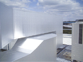
Figure 1 shows some well-installed, well-maintained duct insulation on a below-ambient outdoor duct. The jacketing is a multi-ply laminate.

Figure 2, by contrast, shows an outdoor insulated duct where the jacketing has split open due to a poorly installed duct support (i.e., the sheet metal saddle was not installed as it was supposed to have been) and the duct insulation and jacketing were subsequently poorly maintained. After the split in the jacketing occurred, the insulation was exposed to the atmosphere, resulting in moisture condensation on the duct surface. This problem could have been avoided by having maintenance personnel identify the problem area, remove the wet insulation, replace it with new insulation, and re-jacket it with new multi-ply laminate jacketing.

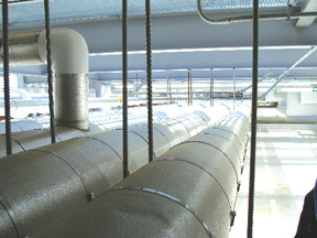
The same principles hold for below-ambient pipe insulation. Figure 3 shows well-installed, well-maintained below-ambient pipe insulation.

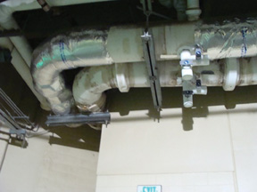
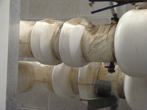
Figure 4, by contrast, shows poorly designed and maintained pipe insulation jacketing on a project that experienced extensive moisture condensation problems. The resulting water and mold build-up is a consequence of both poor design and poor jacketing maintenance. It is not always simple to identify where the problem begins and where it ends. The plastic jacketing shows signs of having been stepped on repeatedly.

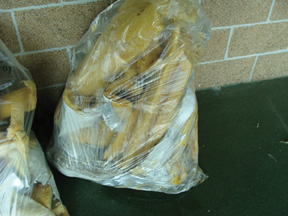
Figure 5 shows a clear plastic bag full of wet pipe insulation materials removed so they could be replaced with new insulation and jacketing. The amount of moisture in the insulation and plastic bag show the consequence of poorly designed and maintained insulation jacketing.

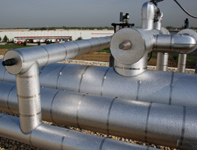
Figure 6 shows outdoor hot and chilled water pipes that have not experienced any moisture condensation problems due to good design, materials, installation, and maintenance. Of course, foot traffic on most insulation systems can be extremely damaging—a fate this system is protected from by its location. The damage is initially inflicted on the jacketing itself, then on the insulation. This is a problem at many process facilities in particular. Once the damage has occurred, rainwater enters the insulation system and eventually results in corrosion, especially if the metal surfaces are uncoated and there are frequent or prolonged maintenance periods when the lines are at ambient temperature.

Figure 7 shows indoor pipes with polyvinyl chloride (PVC) jacketing that has been well installed and well maintained.

Figure 8 shows pipes held together with insulated clamp and groove-type fittings that are jacketed with PVC fitting covers. These covers have been heavily damaged by foot traffic and needed replacement.

Industrial Insulation System Applications

Industrial applications can be even more challenging when it comes to maintaining the insulation and its jacketing. There are several reasons for this, including the following:

  • The applications are generally subject to weather.
  • Corrosive chemicals are often carried in the process pipes.
  • Horizontal pipes are frequently stepped on or even walked on, subjecting the insulation and jacketing to damage.
  • High process temperatures make it impractical to rely on organic coatings and hydrophobic insulations to protect against corrosion under insulation (CUI), so the jacketing is the only real protection.

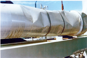
Figure 9 shows a process pipe at an industrial facility that has been properly jacketed. It would appear, however, that this jacketing is relatively new. It is a challenge to keep the lap and butt joints effectively sealed with caulk, a material that will deteriorate over time and is not visible until the jacketing is removed. Maintenance of sealants suffers from the “out of sight, out of mind” syndrome. The only effective solution for outdoor systems is to periodically dismantle a section, inspect the sealants, and determine whether the entire system needs to be resealed.

Figure 10 shows a system that obviously needs to be re-jacketed. In fact, the insulation materials themselves probably need to be replaced with a high-compressive-strength material, assuming the facility owner cannot stop workers from walking on the pipes.

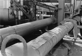
Figure 11 shows “A Tale of Two Pipes.” The pipe on the right has suffered from extensive foot traffic damage, and the one on the left has not (the pipe on the left has been reinsulated with new high-compressive-strength insulation and new metal jacketing). Failure to replace the insulation system on the pipe on the right, as was done on the pipe on the left, likely will result in excessively high heat loss, as well as water intrusion that may, over time, lead to CUI on the process pipe.

When it rains on the pipe with the damaged jacketing and insulation, the water will bypass the jacketing, such as it is, and likely be absorbed by the insulation. When the system is operating, the water will boil off, causing no further damage but resulting in high heat losses due to the high latent heat of vaporization of the leaking water (about a thousand Btus per pound of water, a quantity that can add up quickly with a leaky system in a rainy climate). When the system is shut down for maintenance (assuming that the insulation system itself is not being maintained), the water will migrate to the surface of the pipe, where it is likely to initiate CUI—and CUI is extremely costly to mitigate once it starts.

Figure 12 shows the consequence of corrosion on metal jacketing itself. The aluminum jacketing on the lower pipe was incorrectly specified for this application. It became corroded by leaking fluids from the pipe, a design issue that should have been anticipated. The upper pipe has been re-jacketed with a multi-ply laminate resistant to the corrosive effects of the process fluids.

Financial Justification for Insulation Maintenance

There are several reasons to use thermal insulation in mechanical applications. Whether for energy efficiency, energy savings, process control, condensation control, or thermal comfort in HVAC applications, its use can be easily justified by economics. To attain the design thermal performance, appropriate jacketing must be specified, correctly installed, and properly maintained. If any of these steps are missed, including maintenance, the insulation materials probably will not perform as specified, and the consequence will be higher operations costs. If CUI is a consequence of poorly maintained insulation jacketing, piping system replacement costs can become very expensive.

An example of the costs of pipe replacement when CUI has resulted: for a 3-inch to 4-inch nominal pipe size (NPS) pipe, about 5 man-hours per linear foot will be required to remove, replace, and retest the replacement pipe. With labor costs at a nominal $50 per man-hour, the labor cost would be about $250 per linear foot. Pipe material costs would be about $15 per linear foot, for a total pipe replacement cost of about $265 per linear foot.

Of course, insulation system replacement costs would be additional, perhaps about $17 per linear foot installed, bringing the total pipe replacement cost to over $280 per linear foot. The whole pipe system replacement project would be unnecessary if the insulation jacketing simply had been maintained in the first place, a cost that would be a fraction of the $280+ per linear foot on an annual basis.

Below-ambient air handling ducts and chilled water pipes with a major condensation problem would accrue similar replacement costs for the piping system and the insulation system. In the meantime, if the facility suffers from wet insulation, the owner is paying for much greater energy use, since the wet insulation does not effectively insulate. Further, dripping water can by itself lead to costly problems, e.g., if the water drips onto electrical equipment.

Conclusion

The performance of a thermal insulation material is dependent on its protection from water, water vapor condensation, and physical abuse. Insulation jacketing can provide that protection and thereby ensure the insulation material’s performance. To be successful, however, the jacketing must be properly maintained. A well-maintained insulation system reduces the operating costs of a facility—commercial or industrial. Overall, the benefits of a regular, sustained jacketing maintenance program will far outweigh the costs of that maintenance.

Figure 1

A below-ambient air handling duct, located outdoors, jacketed with a multi-ply laminate. This insulation system has been designed, installed, and maintained properly and hence, by excluding water and water vapor, it is providing the intended insulating performance.

Figure 2

The insulation jacketing, a multiply laminate on the same project shown in Figure 1, has broken open at a support that is missing the sheet metal saddle. While this saddle should have been installed, the lack of maintenance by the facility owner is leading to a significant energy penalty. An immediate repair could have prevented the condensed water build-up in the fiberglass insulation.

Figure 3

Hot and chilled water pipes, located outdoors, with generally well-specified, well-installed, and well-maintained insulation and jacketing. Note that the aluminum jacketing serves only as the weather barrier; the moisture retarder is taped FSK, located between the aluminum jacketing and the insulation.

Figure 4

The insulation jacketing on these chilled water pipes, located in a relatively humid environment exposed to the outdoor air, shows signs of extensive water condensation damage. Once the system started dripping, the owner applied the metal duct tape to the jacketing in a futile attempt to stop the condensation problems.

Figure 5

Soaking wet fiberglass insulation with ASJ materials removed from chilled water pipes. While better late than never, this project had operated for several years with the wet insulation, resulting in extensive corrosion of the pipes as well as excessive energy use.

Figure 6

Hot and chilled water pipes with an insulation system, including PVC fitting covers, that has been well maintained. Admittedly, this system would be difficult to walk on due to its location.

Figure 7

Indoor pipes with correctly installed and well-maintained PVC jacketing.

Figure 8

Insulated fittings with PVC jacketing that have suffered from foot traffic damage. These should be replaced to provide the vapor retarder performance of the PVC jacketing.

Figure 9

Process pipes with well-installed and well-maintained aluminum jacketing.

Figure 10

The aluminum jacketing on this process pipe ought to be replaced as part of the facilities maintenance program. Failure to do so sooner rather than later will likely result in wet insulation that performs poorly and possibly leads to problems with CUI on the process pipe itself.

Figure 11

“A Tale of Two Pipes” shows one (on the left) on which the insulation system has been recently replaced (reportedly with a high-compressive-strength insulation as well as new aluminum jacketing) and one (on the right) still waiting to be reinsulated. This comparison demonstrates clearly the level of damage that can occur from foot traffic.

Figure 12

In this photo, the lower pipe’s aluminum jacketing has apparently suffered from the corrosive effects of the process fluid. The upper pipe has been re-jacketed with a multi-ply laminate that is resistant to this corrosive fluid.

History

Rock and slag insulations, sometimes referred to as mineral wool, have been produced naturally for centuries. During volcanic eruptions, when a strong wind passes over a stream of molten lava, the lava is blown into fine silky threads that look like wool. From this natural inspiration sprang one of the most innovative and versatile insulation products on the market today. Today’s rock and slag wool insulations are high-tech versions of their predecessors, produced from plentiful basalt and industrial slag.

Rock and Slag Wool Composition and Manufacturing Process

Rock wool and slag wool insulations are composed of basically the same raw materials in different proportions and are produced in the same way. Manufacturers use a mechanized process to spin a molten composition of rock and slag into high temperature-resistant fibers. Their similar properties also produce fairly similar performance attributes. The major difference is in the specific volumes of the various raw materials used to make each product.

Rock wool insulation is composed principally of fibers manufactured from a combination of aluminosilicate rock (usually basalt), blast furnace slag,
and limestone or dolomite. Slag is a byproduct from steel production that would otherwise wind up in landfills. Binders may be used, depending on the product. Typically, rock wool insulation is composed of a minimum of 70 to 75 percent natural rock. The remaining volume of raw material is blast furnace slag.
Slag wool insulation is composed principally of fibers manufactured by melting the primary component, blast furnace slag, with a combination of some natural rock, with or without binders, depending on the product. Typically, slag wool insulation uses approximately 70 percent blast furnace slag, with the remaining volume of raw materials being natural rock.

Rock and Slag Wool Benefits

Rock and slag wool insulations offer a wide array of benefits for specifiers, designers, and builders interested in using materials offering environmentally responsible characteristics and demonstrating proven performance. These benefits include the following:

  • Thermal performance. Rock and slag wool insulations are tested to all applicable industry standards to ensure their R-value does not deteriorate over time. Loose-fill rock and slag wool insulations resist settling, and batt products spring back after average compression, so installed thermal performance is maintained over the life of the product.
  • Fire resistance. Rock and slag wool insulations are naturally non-combustible and remain so for the life of the product. These insulations can resist temperatures in excess of 2,000°F. Because these products have a high melting temperature, they can be used in a wide variety of applications that call for these unique properties. These products meet NFPA 220and American Society for Testing and Materials (ASTM) E136 standards and test methods, and are Class A product tested per ASTM E84 and NFPA 101. Rock and slag wool insulations are used as passive fire protection in many buildings.
  • Sound absorption. The fibrous structure and high density of rock and slag wool insulations offer excellent sound absorption properties, making these products an outstanding part of systems designed to reduce sound transmission.
  • Mold, fungi, and bacteria resistant. Rock and slag wool insulations resist the growth of mold, fungi, and bacteria because they are inorganic.

The fibrous composition of rock and slag wool insulations provides a flexibility and versatility not found in most other insulations. Rock and slag wool insulations come in a wide variety of forms, shapes, and sizes, including board, batt, loose-fill, spray-applied, and pipe insulation for many common and specialized applications.

Environmental Benefits

One of the most important environmental benefits of rock wool and slag wool insulations is their ability to make buildings and equipment more energy efficient. A thermally efficient building or system reduces the amount of energy required to maintain it.

Slag wool is made from blast furnace slag, a waste byproduct of steel production. The industry estimates that over 90 percent of the slag used for insulation is purchased directly from steel manufacturers. The remaining 10 percent is mined from waste disposal sites and landfills. Between 1992 and 2005, slag wool insulation manufacturers used over 13 billion pounds of waste blast furnace slag in the production of insulation.

Readers who are interested in learning more about the insulation material featured here should visit the MTL Product Catalog at www.insulation.org/MTL or visit the NIA Membership Directory at www.insulation.org/membership to fid a manufacturer.

NIA Members who would like to author a future Insulation Materials column should contact publications@insulation.org.

Figure 1

In the November 2007 issue of Insulation Outlook, “Insulation Systems: Doomed From the Start?” discussed some conditions that can doom mechanical insulation to failure (see www.insulation.org/articles/article.cfm?id=IO071102). The article highlighted the term “value engineering” as it pertains to mechanical insulation, considered how mechanical insulation seems a forgotten technology, and described the effects of compressed schedules that do not give many trades sufficient time to install their systems properly. The article also discussed careless mechanical system installation, including improper installation of insulation materials and carelessness on the part of the insulation contractor. With that as background, this article provides possible solutions to the problems of mechanical insulation failure, starting at the beginning of the construction process. At every subsequent stage of the process, this discussion will shed light on mechanical insulation, “the forgotten technology.”

The importance of the owner and architect recognizing the value of mechanical insulation when developing a project’s construction and completion schedules cannot be overemphasized. The mechanical insulation portion of the construction process is usually at the end of the schedule. The window for the insulation contractor may be smaller as a result of delays at the front end, but no extensions typically are given at the back end. Insufficient time to properly complete the insulation process equals potential for mechanical insulation failure. The owner and architect must recognize the importance of every trade in the construction process. Mechanical insulation is not the only trade that suffers from poor project scheduling. The entire project will suffer if scheduling is not properly considered from the beginning. Many problems can be avoided by considering the trades that get involved at the end of the schedule when planning at the beginning. Specifically, mechanical insulation will be less likely to fail if adequate time is afforded the installing contractor.

With a realistic construction schedule, attention turns to the design team and the mechanical engineer to prepare the drawings and documents for the project. In far too many cases, the mechanical engineer will go to the library, pull an old insulation specification off the shelf, and put it into the bid package. Much of the included specification will not have anything to do with the current project, but it is quicker and easier than developing a specification for the particular job. Specifications for old projects that are used as generic specs for all projects have a tendency to allow the engineer to avoid considering all of the important ramifications of a specific job as it relates to the mechanical insulation. Has the humidity of the space as it relates to the use of the building and the equipment that will be installed been considered? How about new materials available on the market? Do the specifications take into consideration the space available to install mechanical insulation? Have the design criteria—as they relate to mechanical insulation—been adequately considered? If these items are not identified and addressed at the beginning stage of the process, there is a likelihood that failures will occur at the end. The mechanical insulation will become very important when the systems fail and the owner, architect, engineer, general contractor, and mechanical contractors are all trying to figure out why.

Getting It Right the First Time

As an example, consider a building that has been beautifully designed by the architect. The mechanical engineer has identified the proper insulation materials specified for the project based on the use of the building and the conditions under which the mechanical systems will function. The construction process is beginning. The mechanical contractors have been selected and have begun the process of installing pipes for the plumbing and heating systems, as well as the sheet metal for the ventilation. The general contractor has decided that he would rather allow the mechanical contractors to award the mechanical insulation so that he does not have to handle it. The mechanical contractors request insulation prices from various contractors who specialize in installing insulation materials. The insulation contractors are asked to “sharpen their pencils” because everyone has been asked to reduce their prices to get the project under budget. In short, the insulation contractors are asked to value engineer the project to bring it in under budget.

As described in the earlier article in this series, value engineering in far too many cases means either eliminating the insulation or reducing the thicknesses of the materials to reduce the install cost of the project. The owner of the building has no idea that this value engineering is taking place. The owner thinks the final product is going to be the quality building that is being paid for, but when value engineering comes into play, the integrity of the mechanical insulation system is frequently compromised. There are, of course, times when a different material can substitute for the one specified and reduce project costs. All too frequently, however, quality is what gets compromised.

In this case, the owner insists that the mechanical insulation not be compromised: He wants the type and thickness of materials for which he is paying. The bidding process is now complete, and a contractor has been selected. The owner, architect, and mechanical engineer all have been educated to understand that value engineering when it comes to insulation is a bad idea. The project will go forward with the quality specification the engineer selected. Those involved with this project are not forgetting the insulation.

The general contractor (GC) is in a very influential position at this point in the process. If the GC understands the importance of mechanical insulation, he or she can instruct all mechanical trades to install their systems with insulation in mind. The GC can require that the insulation contractor attend the job meetings—which works much better when the GC has made the award and controls the insulation. The GC can insist that the systems be installed with adequate clearance for the insulation and can instruct the other trades to remember that the mechanical insulation must be installed properly—therefore, they are obligated to pay attention to the insulation process.

Now, the piping systems are being installed, and the core openings are not in perfect center. The pipe will fit; it just will not be centered. The insulation contractor will have to make it work. The selected insulation contractor has taken the time to visit the project in the early stages of construction and has noticed this problem. The insulation contractor will discuss this issue with the mechanical and general contractors to ensure that the pipe systems are installed properly to allow for the pipe insulation to be installed. The problem is rectified early in the process. The same thing happens when the pipes are installed too close together to allow for the specified thickness of the insulation materials. It happens again when the sheet metal is installed directly on the chilled water piping system. All parties in the construction process are put on notice by the insulation contractor that the mechanical systems must be installed with adequate clearance to allow for the specified insulation thicknesses to be installed. If this does not happen, the insulation contractor cannot be held responsible for potential failures in the future.

There is no question that in the construction business, nothing is perfect. Mechanical insulation contractors do not expect perfection but can and do expect that their portion of the project be considered by all parties. The National Insulation Association (NIA) and its affiliated regional associations are working to shed light on mechanical insulation (the forgotten technology). Owners, architects, mechanical engineers, and mechanical contractors cannot be expected to be as vigilant about insulation as NIA members are. It can be expected, however, that at this time in history—with the cost of oil and gas going up daily—all parties involved in the construction process become aware of the value of mechanical insulation and address it accordingly. Properly worked-out schedules, with attention paid to details regarding insulation types and thicknesses, as well as the proper clearance for material installation, will help contractors avoid many problems at the end of the project.

In the Save Energy Now (SEN) initiative of the U.S. Department of Energy’s (DOE’s) Industrial Technologies Program (ITP), Energy Savings Assessments (ESAs) of steam as well as other industrial plant systems are performed to identify energy conservation opportunities. Steam System Assessments consider the design and operation of the plant in the context of the BestPractices steam criteria. The adequacy of thermal insulation for piping, tanks, and other elements of the distribution systems are among the characteristics evaluated. The analysis approach involves observing the condition of the distribution system and using the 3E Plus® insulation tool and the Steam System Assessment Tool. Readers who are unfamiliar with these tools are encouraged to visit the BestPractices Steam website at www1.eere.energy.gov/industry/bestpractices/steam.html.

The condition of the thermal insulation observed during the Steam System Assessment varies. In some cases, limited repair of damaged insulation and the addition of insulation previously missing on steam supply lines are the only requirements. This may affect as little as 10 percent of the length of steam mains and laterals. In other cases, however, the length of steam piping affected is more significant due to systems having undergone substantial alterations without replacement of insulation. The insulation of valves, pipe sections with gauges and sensors, and “T” sections and elbows is another frequently observed opportunity.

The conditions associated with condensate return systems vary even more widely. In some circumstances, the energy conservation opportunity is limited to selected repair of condensate mains and laterals. However, in other cases, the condensate piping is found to be completely non-insulated, as it was believed to be unnecessary because of the following:

  • The lower temperature of the pipe
  • The fact that the losses are often to conditioned spaces

Despite these perceptions, eliminating the uncontrolled loss of energy to various spaces usually represents an energy conservation opportunity. This article provides reflections—from an owner’s perspective—from six recent steam system efficiency improvement projects.

A Good Place To Start

In a food processing plant using high-pressure steam for sterilizing and cleaning operations, the steam system is the backbone of the operation. The system in this plant is old, and had not been well maintained over a period of several years, as evidenced by leaks and deteriorated or missing insulation in many areas.

The new plant engineering manager had received a mandate to reduce utility costs. His initial response was to insulate distribution piping—steam and condensate that carried steam from the boiler plant to the end-use loads through the maintenance shop. Based on the system assessment, several measures were recommended, including eliminating leaks, improving boiler efficiency, and performing additional insulation repairs.

The plant engineering manager needed a “quick fix” that was visible as a statement to both corporate management and the maintenance staff that things were improving. The assessment validated the cost-effectiveness of the investment in pipe insulation, showing a payback of 1 year or less on additional insulation that would save $45,000 per year. Since completing the assessment, additional insulation repairs have been performed, along with leak repairs and other operational improvements.

Distribution System Effects

Distribution system energy losses can vary from 10 percent to more than 25 percent of a central boiler plant’s output. A major factor influencing these losses is the length of steam and condensate piping that the plant serves, along with the condition of the insulation. Based on the existing conditions found at one facility—with a system consisting of more than 1 mile of steam piping—reducing the losses from uninsulated segments lowers thermal losses from 15 percent of average boiler output to 4 percent. The insulation work involved less than 20 percent of the mains and laterals. The work on the condensate return system involved about 1/2 mile of pipe. Losses represented about 15 percent of average boiler output, while the fully insulated condensate piping is reduced to 4 percent of boiler load.

At a plant with an installed boiler steam output capacity in excess of 175,000 parts by weight per hundred parts by weight (PPH), and an extensive distribution system made up of both underground and overhead piping, the recommendation to improve plant insulation was the first to be implemented. The owner’s representative recently reported that the insulation work was reducing energy, but the extensiveness of the need at this facility required that the work be phased with the distinct subsystems’ insulation to be repaired in a sequential manner. The owner’s representative realized that some level of attention would be needed on a continuing basis—a key observation for sustaining the benefits the plant was beginning to realize.

Steam Generation Capacity And Actual Conditions

As a corollary to the preceding observations, steam systems serving manufacturing operations with a large space footprint will expend a significant part of the plant output keeping the steam lines hot and supplying auxiliary steam for plant operations. For example, a plant that was recently assessed had two central plants—each with less than 20 million British thermal units per hour (mmBtu/hr) of output capacity—was estimated to use almost one-third of the exported steam keeping the distribution system hot. At this plant, the steam condensate is returned at a low temperature—less than 150°F. This results in the need for a significant auxiliary steam load to raise the condensate temperature to boiler entrance conditions. Not correcting this deficiency would pose a threat to boiler life due to thermal shock.

Repairing the insulation on the steam lines, adding insulation to previously uninsulated condensate return piping, and taking steam and condensate piping out of service to abandoned operations were among the most cost-effective opportunities identified at this site.

At the same location, the condensate-receiving tank was not insulated. This was found to add losses of 400,000 Btu/hr, adding 20 percent to the losses from the piping system. With this justification, the owner’s representative contracted to have the tank insulated.

As with the prior case, the owner’s representative indicated that the recommendations relating to the thermal insulation deficiencies were among the first to be implemented. He expected that the work would continue as an ongoing process.

Relative Value

At another manufacturing plant, improving the insulation on a steam and condensate piping system that consists of about 1 mile of mains and laterals was estimated to save more than 6 mmBtu/hr—about the same savings that would result from the addition of a feedwater economizer in the central plant. However, the payback of a year or less for the insulation measure is much more favorable than the 4- to 6-year payback associated with the economizer.

As a result, the insulation work was initiated, and the economizer is still considered an interesting idea.

More Than Economic Merit

A recent assessment of a beverage bottling facility provides another example of the importance of insulation repair projects to system efficiency programs. The review of the overall system identified numerous opportunities, including burner change-outs, boiler operating changes, process control improvements, and insulation. The deficiencies were identified early in the assessment during field surveys of existing conditions. The insulation opportunity was discussed with the owner’s representative, who responded by hiring insulation contractors to replace the missing insulation.

The work was done quickly, the results were visible, and the payback was fast—less than1 year. As with the food processing plant, the plant started realizing energy cost reductions immediately, and the newly reinsulated pipe caused a boost in maintenance staff morale.

Underground Piping

Many steam systems, especially district systems, transport steam through buried pipes and underground vaults with branch connections and blocking valves. Buried piping can benefit from the insulation qualities of typical soils, unless there are leaks or high groundwater levels. The challenge with underground systems is typically maintaining insulation quality in manholes and underground vaults. These areas are where maintenance activities are most likely to occur and are subject to the usual wear-and-tear and attention-to-detail issues that all too often allow long-term degradation of pipe and valve insulation to occur. While the piping in manholes may only represent 2 to 5 percent of the overall system length, as the examples above have shown, small sections of uninsulated piping and valves have a significant impact on distribution system energy losses.

This was illustrated during another recent activity involving a large steam distribution system with more than 10 miles of steam and condensate mains and laterals. At this site, analysis has shown that improving manhole conditions, including steam and condensate pipe insulation repairs, is estimated to save about $500,000 a year, with a payback of about 1 year.

Final Tips

What does it take to minimize steam system losses due to substandard insulation over an extended period? The following comments from owners’ representatives provide good guidance:

  • Get started somewhere—but get the work started.
  • Stay at it. As several of the examples cited above indicate, it is a long-term process.
  • Savings will be apparent quickly, and returns on the investment are rapid. Additional benefits include cleaner plant spaces and improved morale for facilities engineering and maintenance employees.

To reduce administrative time hiring insulation contractors for what can be many short-term tasks, some representatives also indicated that they established long-term contracts that set out agreement conditions and costs, authorizing specific tasks under “task orders.” Task-order contracts can expedite the front-end time to get a specific insulation task completed.

History

Polyolefin closed cell tubular insulation was developed in Europe in the 1970s. Much of the development work was done in Belgium. It was first introduced in the United States in 1979 as a do-it-yourself insulation in semi-slit, three-foot lengths. During this time, the country was undergoing our first energy crisis, with government rebates for home insulation improvement, so polyolefin insulation quickly caught on as a pipe insulation for domestic hot and cold water.

During the early 1980s, a preslit/preglued product was introduced and polyolefin insulation was brought to the commercial market for hot and cold water, drain pipes, and other applications. The market migrated to the preslit and preglued, 6-foot product as the main product offered in ⅜ -, ½-, ¾- and 1-inch wall up to 4-inch iron pipe size (IPS) IDs. Further advances of the product into lower-temperature applications, including cryogenic industrial applications, came in the late 1990s. Although it has found successful applications in the industrial market, the primary market for polyolefin insulation continues to be plumbing—hot and cold water, and roof drains.

The Manufacturing Process

Polyolefin closed cell tubular insulation is predominately comprised of polyethylene resin, which is one of many resins in the polyolefin family. For this reason, the product is also often referred to as polyethylene insulation. Other resins in the family would be polypropylene and ethylene vinyl acetate. Polyethylene resin has a very sharp melting point, and this characteristic is key to the manufacturing of the product.

To begin the manufacturing process, polyethylene resin pellets are fed into an extruder along with other ingredients such as UV and heat stabilizers, colorants etc, which are also in pellet form. All of these materials are melted and blended together.

In the second phase of the extrusion process, a physical blowing agent (typically a hydrocarbon), which is in the form of a gas, is injected into the extruder under high pressure and blended into the molten mixture. The material is under pressure in the extruder as it is pushed through a die at the end of the extruder, forming the tubular shape. The die consists of an outer ring with a pin in the center that forms the ID of the tube. As the material exits the die, it immediately expands as the blowing agent normalizes the pressure. Because the mixture exits the forming die at a temperature very close to the melting point of the resin, it quickly sets up or solidifies and maintains its cellular structure rather than collapsing its shape. The material is then cooled down completely, cut to length and packaged.

The product can be slit and pressure-sensitive adhesive can be applied to the seam, if requested, during the cooling process. The process runs quickly, and there is little waste. Any scrap generated during the manufacturing process can be recycled back into the process since the material remains a thermoplastic and it can be remelted.

Product Characteristics

The majority of polyolefin insulation sold is in tubular form. The current preformed size limitation is 4-inch IPS x 1-inch wall. The product can be sleeved to achieve greater wall thicknesses. Manufacturing methods are currently under development to expand both the ID and wall size range.

The product gets its physical property characteristics from its base resin (polyethylene) and the fact it has a closed-cell structure. Polyethylene resins offer great water, chemical, and abuse resistance as evidenced by its other applications, such as beverage containers, trash bags, life jackets, and other consumer items. The closed-cell structure of polyolefin insulation also provides its thermal properties (k value).

Polyolefin insulations are identified by American Society for Testing and Materials (ASTM) C 1427. They are suited for applications within a temperature range of -150°F to 200°F, which fits well with their primary application of hot and cold water lines, as well as roof drains. Polyolefin insulations have low water-vapor permeability characteristics, as evidenced by a water vapor transmission (WVT) permeability rating of .05 perm-inch max. Caution does need to be taken not to use these materials on above ambient temperatures applications above 200°F.

Polyolefin insulations are easy to work with. No special tools or protective clothing are required. The most predominantly used form is preslit/preglued, which almost eliminates the need for additional adhesives on most jobs. It can be easily fabricated in the field with a sharp knife.

Common applications include the following:

  • Hot and cold water (domestic and commercial)
  • Roof drains
  • Cold process pipes and equipment
  • Heating, ventilating, and air-conditioning (HVAC) equipment

Specific physical properties of the material can be found on the National Insulation Training Program (NITP) chart at www.insulation.org/techs/MaterialsSpecs.pdf under Polyolefin Sheet and Tube.

Additional information can be found in the Manufacturers’ Technical Literature (MTL) Product Catalog at www.insulation.org/mtl or on specific manufacturers’ websites.

Readers who are interested in learning more about the insulation material featured here should visit the MTL Product Catalog at www.insulation.org/MTL or visit the NIA Membership Directory at www.insulation.org/membership to find a manufacturer.

NIA Members who would like to author a future column should contact publications@insulation.org

Figure 1

Most people think of mold as a problem on ceilings or walls. Seldom do people consider mold as it pertains to mechanical insulation. Mold growth on mechanical insulation is usually a result of insulation failure, poor design conditions, or improper piping installation techniques. In many cases, the problem results from a combination of these factors.

Mold needs water, an organic food source, and oxygen to survive. The oxygen supply is virtually everywhere in buildings. Therefore, the water source and food supply have to be controlled. This article describes various building mold problems that resulted from failures in the insulation, engineering, and piping installation techniques. It also explores how these problems can be avoided.

Situation One

Consider the example of a standard, 35-story, high-rise condominium. The building is under construction and the first 15 or so floors are in various stages of completion. The schedule for this project is very tight. Many of the condo units are sold, and the buyers have move-in dates that must be met.

The heating and cooling for the building is a three-pipe, dual-temperature, stacked-fan, coil system. The ductwork associated with the system is lined with 1-inch-thick fiberglass for sound attenuation for the first 10 feet, and then insulated with 1½-inch-thick, 1-pound- density fiberglass blanket with foil skrim kraft (FSK) vapor barrier. The lower floors have pre-insulated pipe insulation on the risers. As the fan coils are installed, the general contractor is requesting that the tie-in insulation at each fan coil unit be installed. The roof is not on the building yet, windows are not installed on the upper floors, and rain and snow blow onto the upper floors and run down the risers into the pre-insulated material and the new tie-in materials. The lined ductwork collects the moisture from the floors above.

Water (abundant from the floors above), an organic food source (such as the paper vapor barriers and paper on the drywall materials), and oxygen are the factors needed for mold to grow. Conditions in this building make it a recipe for failure. However, it could have been avoided if the building’s owner was made aware of the problems his schedule would create for those who purchase the condo units, or if the roof and windows were installed prior to the mechanical insulation systems.

This is a difficult financial decision. Selling the units as quickly as possible is the most important factor in the financing and construction of the building. Changing the schedule and/or sealing the building from weather in segments can help mitigate water problems in high-rise buildings. Allowing insulation materials to get wet prior to the building’s completion will create a long-term problem for the building occupants and an expensive fix in the future when mold begins to show on the walls and ceilings.

Situation Two

The next example is of black mold growth on the ceilings and on the walls where they meet the floors of dormitory rooms. Because of the mold growth, the dormitory must be closed until the problem is resolved. Upon inspection, it is apparent that a condensate pan drain connection is loose, and condensate from the pan is running onto the floor and wicking up the walls.

The pipes above the ceiling are another problem. Removing the ceiling tile reveals black spots on the pipe insulation. The material is standard 1-inch-thick fiberglass with all-service jacket (ASJ) on chilled water pipes. Where the connections are made to the fan coils, however, the pipes and valves are installed too close together to allow for the 1-inch-thick fiberglass with ASJ. The insulation contractor took some liberties with the system and changed the material to ½-inch-thick fiberglass with ASJ.

When the old material is replaced, the condensation problem continues. From further inspection of the building it is clear that the humidity in the public areas is very high. The design condition is not the same as the installed condition. The air-handling units feeding the common areas are not sized properly to remove the moisture from the air. Combine this problem with the disconnected pan drain pipes and the fact that the insulator was forced to install insulation materials prior to the sealing of the building envelope—which allowed water infiltration into the system—and the result is an extreme failure. It is likely that this problem could have been avoided if the air-handling units had been designed properly.

Situation Three

This example involves the mechanical system of a large public performance venue, where mold is growing on the pipe insulation and the fittings in various areas of the building. The specification is standard fiberglass with ASJ vapor barrier jacket. Theoretically, this specification should be adequate for the service. Upon inspection, the workmanship is excellent. All of the seams are sealed with mastic, and all of the fittings are sealed as well.

A test of the mastic samples, however, indicates that it is breathing mastic—not a vapor barrier. Vapor barriers are critical in chilled water installations. The owner of the venue had the entire system removed and replaced. The problem resulted from an improperly installed mechanical insulation system. Using the proper materials is critical on chilled water systems.

Situation Four

This example features a low-rise condominium with 4 floors and approximately 10 units per floor. The units are heated and cooled with a dual-temperature pipe system. There are no expansion joints in the system to compensate for the expansion and contraction when the cooling cycle is changed to heating. The specification is standard fiberglass with ASJ vapor barrier. Again, the specification is adequate for the system, providing the design is consistent with the actual building condition. A walk through of the building reveals discoloration on the vapor barrier, along with some indication of mold growth on wall penetrations and at some ceilings.

This building had many installation problems, as well as design flaws. Every condo unit has a 4-foot sliding door to a balcony. At any given point in a day, as many as 40 of these doors could be open to the hot, humid outside air of the summer. The common area, which is where most of the failures occur, has a makeup air system with returns that run through the various condo units. The returns pick up the outside, humid air and deposit it into the common area. The ball valves do not have extensions to allow proper insulation of the valve bodies. There are no sleeves where the pipes penetrate the walls. The condition of this building is the result of design failure, mechanical installation failure, and insulation installation failure.

Mold Makeover

Mold growing on mechanical insulation services is a problem that potentially begins with the architectural phase of the building and is exacerbated by the design engineering, the general contractor’s compressed schedule, the mechanical contractor’s poor pipe installation practices, and finally the insulation contractor trying to make it all work to accommodate all of the other parties. These conditions exemplify the importance of all parties involved in the mechanical service paying more attention to the cooling cycle for buildings. Insulation contractors should be prepared to write letters to the parties with which they have contracts to inform them that there is potential problems with the cooling cycle.

The wrong time to tend to proper mechanical insulation is after the building is finished and occupied. Schedules should allow for the proper installation of insulation materials. The design should consider the building envelope and building use, along with the equipment specified. The mechanical contractors should install the systems in such a way as to allow for proper mechanical insulation installation. Finally, the insulation contractors should keep all parties informed when they see conditions that may cause failures in the building’s future.

The evolution of closed cell elastomeric foam, first developed in the early 1900s, has had a dramatic impact on the insulation industry. The most notable reason for this is its high moisture resistance, the result of its cellular structure—millions of tiny barriers that resist the migration of liquid. This characteristic not only minimizes the threats associated with moisture (such as mold), but it also ensures steady, long-term thermal performance. Liquid has a high heat transference capability; hence, wet insulation provides very little insulation at all. Closed cell elastomeric foam has strong water vapor permeability to resist moisture absorption, so neither its performance nor its durability is impaired by the presence of moisture in a heating, ventilating, and air-conditioning (HVAC), plumbing, or refrigeration system.

History

Elastomeric foam insulation was developed in the 1950s. The introduction of this and other polymer-based materials marked an important industry transition from the use of natural materials, such as cork, to the use of synthetic materials and chemicals. The popularity of elastomeric insulation grew quickly, primarily because it eliminated the need for any type of vapor barrier to prevent the transference of moisture. As availability of the insulation in various forms (including sheets, rolls, and tubes) increased, so did its popularity as an insulator, especially in refrigeration piping and ductwork applications. It was a user-friendly alternative to other materials because it could be bonded reliably to a variety of surfaces, it was easy to install, and its performance could not be compromised by tears or punctures.

Demand for elastomeric foam has increased sharply over the last 2 decades due to heightened awareness of indoor air quality (IAQ). Since elastomeric foam does not contain formaldehyde or fibers, and has very low volatile organic compounds (VOCs), it has found wide acceptance among IAQ advocates. Because of its non-particulating, smooth surface and moisture resistance, elastomeric foam does not support the growth of mold—arguably one of the most devastating IAQ problems that facilities face.

The Manufacturing Process

The three main components used in the manufacturing of elastomeric closed cell foam insulation include the following:

  • Synthetic rubber blend, typically nitrile butadiene rubber (NBR) and/or ethylene-propylene-diene monomer (EPDM)
  • Polyvinyl chloride (PVC)
  • A chemical foaming agent

These components are combined in a large mixer, typically in batches of 500 pounds or more. The mixture is then put through extruding equipment to form a particular profile or shape, typically either a round tube or a flat sheet. The profile is heated in an oven to a specific temperature, a process that causes the chemical foaming agent to change from a solid to a gas. When this occurs, thousands of tiny air pockets (cells)—all of which are connected—form. The profile is carefully cooled to ensure that these cells remain unbroken and intact, maintaining the material’s closed cell structure. It is then cut to size and packaged for shipment. 

Elastomeric foams are made without the use of chlorofluorocarbons (CFCs), hydrochlorofluorocarbons (HCFCs), or hydrofluorocarbons (HFCs), making them suitable for the toughest environmental specifications.

Common Applications

Closed cell elastomeric foam has been successfully used as pipe insulation since it was  patented in 1954. Available in a wide range of shapes and thicknesses, elastomeric foam can be easily manipulated to fit snugly around all kinds of equipment, from residential piping to large commercial chillers. There are closed cell elastomeric foams that meet all of the code requirements, fire ratings, noise blocking, and efficiency standards for a variety of applications, including the following:

  • Refrigeration piping, hot and cold water lines, and chilled water piping
  • HVAC components
  • Interior and exterior duct systems
  • Chillers
  • Mechanical systems in industrial, pharmaceutical, and marine and offshore applications
  • Solar installations

Recent Advances

Over the years, there have been several advances in the production of elastomeric foam, making it suitable for particularly demanding applications. These advances include:

  • a non-halogen foam suitable for use on stainless steel at high-temperature applications (up to 250ºF);
  • high-temperature foams suitable for up to 300ºF;
  • availability of more colors, including white, which saves users the extra time and expense of priming or painting on indoor applications; and
  • laminated products for exterior applications where insulation would be subjected to ultraviolet (UV) exposure, weather, and physical abuse.

Perhaps one of the most exciting advances in elastomeric foam is the recent availability of insulation with a built-in antimicrobial additive.

Summary

Moisture resistance remains closed cell elastomeric foam insulation’s strongest selling point when compared to other insulating materials. This also makes it great for below ambient applications, where condensation is an issue. Solid thermal performance, user-friendly installation, durability, and appealing IAQ characteristics make it suitable for the full range of HVAC, refrigeration, and plumbing applications. The product will not absorb moisture, or trap dirt or debris that supports the growth of mold. It is a fiber-free, formaldehyde-free, low-VOC material, so it is a good candidate for those facilities that are especially concerned with IAQ.

Figure 1

  1. All properties are for the generic material type and will vary by grade and by manufacturer. All properties should be verified with individual manufacturers. Properties that are not stated may or may not be an indication that a material is not appropriate for applications depending on that property. This should be verified with the specific manufacturer.
  2. Surface burning characteristics are valid for 1-inch thickness; verify results for type and any other thickness with the manufacturer.
  3. When a property is out of the specified usage range, it is shown by N/A3. Properties that are not listed or stated are so shown.
  4. All properties listed are for the core insulation material only and may not be indicative of the performance of an insulation system, including vapor retarders, adhesives, and sealants.
  5. Many materials can be used for applications outside of the ranges listed, but additional precautions must be followed. The specific manufacturer should be consulted for detailed recommendations.
  6. Some values, such as specific thermal conductivities at various mean temperatures, may be interpolated value.
  7. This chart has been established for products with current ASTM standards.

History

Cellular glass insulation was developed more than 60 years ago. It is believed to have been a modification of technology that existed in Europe at the time. It was discovered that by making glass, then destroying it and baking the glass powder (with certain additions to the batch), a cellular glass “bun” could be created.

The beauty of the bun was that it was 100-percent glass with insulating and flotation properties. The glass composition made it moisture, high heat, and fire resistant. The cellular nature of the glass provided insulation and flotation. Thus, the search for new end-use applications began.

One of the first such end uses was in flotation blocks for submarine nets in U.S. harbors during the latter days of World War II. At the time, cork was in short supply and it was discovered that the cellular glass would remain buoyant and continue to hold up the nets, even after being split up by gunfire, which would originate from submarine surface guns.

At the time, cork was also used as an insulation in cold storage facilities. Because of the moisture resistance of cellular glass, it was a natural fit for cold storage or cold process service, because the vapor drive from ambient air to a cold surface creates great potential for insulation saturation. This was not a problem for cellular glass, which is resistant to such vapor drive. Thus, from the 1950s to the 1970s, the use of cellular glass in cold storage facilities became common. At this time, cellular glass insulation would also find its way into the below-ambient industrial piping and equipment markets.

As a natural outgrowth from cold storage applications, cellular glass insulation began to be used in commercial roofing. In fact, cellular glass was the first insulation to be manufactured into a “tapered” roof insulation, which enabled conversions of “flat” roofs to “low slope” roofs.

The dimensional and strength properties of cellular glass insulation led to the use of the material in load-bearing applications. Higher density grades of cellular glass insulation were developed and, as a result, today more than 90 percent of liquefied natural gas (LNG) storage tanks worldwide are built on a cellular glass insulation base.

Eventually, with more utility systems being installed underground–direct buried, in trenches, or in tunnels–ground water resistance became a major factor in insulation systems retaining their original thermal properties. It was determined that cellular glass worked well in these installations because of its resistance to water. Jackets and finishes were then developed to ensure that physical damage to the cellular glass would not take place during the backfill process.

Over the years, more end uses have emerged that require high-performance insulation systems using cellular glass. For example, systems that cycle from very low temperatures to very high temperatures create the potential for an insulation’s dimensional instability. Cellular glass is able to withstand these temperature cycles without affecting the product’s dimensional stability. 

New applications for cellular glass insulation have continued to develop. One such application niche involves a growing number of plants that have to deal with flammable liquids as a part of their processes. It has been determined that insulations may “wick” flammables like oil and other chemicals, which can provide an ignition or fuel source in the event of a fire. Because cellular glass insulation is non-combustible and nearly 100-percent closed cell, cellular glass insulation has become the standard product in these applications.

The Manufacturing Process

To manufacture cellular glass, the glass itself must be made. The material is then drawn out of a melter at very high temperatures and allowed to cool. The cooled glass is pulverized to a fine powder, and foaming agents are added. The resulting “ground batch” is measured into pans, which pass through cellulating furnaces at approximately 1,000°C, where the material begins to foam.

The resulting “buns” are removed from the cellulating furnaces and placed into annealing ovens for several hours before finally being transferred to the finishing process. There are multiple steps in the quality assurance processes to ensure that there are no defects in the blocks. After inspection are palletized and shrink-wrapped before being shipped.

Globally, the majority of cellular glass insulation is used in block form. However, for industrial insulation applications, the cellular glass insulation blocks are fabricated to produce pipe insulation, fitting covers, and other special shapes by a distributor or fabricator. ASTM C1639 serves as a guide for fabrication of cellular glass insulation.

Product characteristics of cellular glass include the following (testing certifications available from manufacturers):

  • Moisture Resistant
  • Permeability: 0 Perm in
  • Will Not Wick Flammable Liquids
  • Consistent Insulation Values (No Aging)
  • 100-Percent Glass/No Binder or Fillers  
  • Flame Spread 0/Smoke Developed 0
  • High Compressive Strength
  • Wide Temperature Service Range
  • Dimensionally Stable
  • Non-Combustible

Cellular glass insulation for mechanical insulation applications should be manufactured to comply with American Society for Testing and Materials (ASTM) C 552—Standard Specification for Cellular Glass Thermal Insulation.

Common Applications for Cellular Glass

  • Chilled Water Pipes and Equipment
  • Stainless Steel Hot Water Lines
  • Hot Oil Piping and Equipment
  • LNG Piping
  • Green Roof Insulation
  • Underground Steam Distribution
  • Cold Process Pipes and Equipment
  • LNG Tank Bases
  • Ethylene Plant Pipes and Equipment
  • Fireproof Building Panels

Manufacturers of cellular glass have traditionally participated in important NIA committees, and their technical information can be found in the following locations: the Manufacturers Technical Literature (MTL) Product Catalog at www.insulation.org/mtl, on the MTL Product Catalog CD, within the National Insulation Training Program (NITP), and in the Midwest Insulation Contractors Association (MICA) Insulation Standards CD. Websites are also a good source for up-to-date technical information about cellular glass.

Figure 1

  1. All properties are for the generic material type and will vary by grade and by manufacturer. All properties should be verified with individual manufacturers. Properties that are not stated may or may not be an indication that a material is not appropriate for applications depending on that property. This should be verified with the specific manufacturer.
  2. Surface burning characteristics are valid for 1-inch thickness; verify results for type and any other thickness with the manufacturer. (Not applicable to cellular glass.)
  3. When a property is out of the specified usage range, it is shown by N/A3. Properties that are not listed or stated are so shown.
  4. All properties listed are for the core insulation material only and may not be indicative of the performance of an insulation system, including vapor retarders, adhesives, and sealants.
  5. Many materials can be used for applications outside of the ranges listed, but additional precautions must be followed. The specific manufacturer should be consulted for detailed recommendations.
  6. Some values, such as specific thermal conductivities at various mean temperatures, may be interpolated value.
  7. This chart has been established for products with current ASTM standards.