Category Archives: Material Selection

A chilled-water system can be defined as a re-circulating water system using water chilled in a refrigeration machine as a source for cooling. In most commercial applications, this cooled water is used as part of an HVAC system for conditioning the temperature of the air in a room or building. We often think about the need for conditioned air as a simple modern comfort. However, with today’s technologically advanced equipment and our growing reliance on machinery, air conditioning is becoming a necessity in almost every building.

These advances have led to increasingly complex chilled-water systems requiring more specialized insulation solutions. Choosing the right materials, identifying the components that require insulation, and selecting a qualified contractor for installation are the major requirements for a successful chilled-water project.

While there are many different types of pipe and equipment insulation used today, the list of materials that are compatible with a cold system is quite narrow. Figure 1 lists some of the most common cold-application materials:

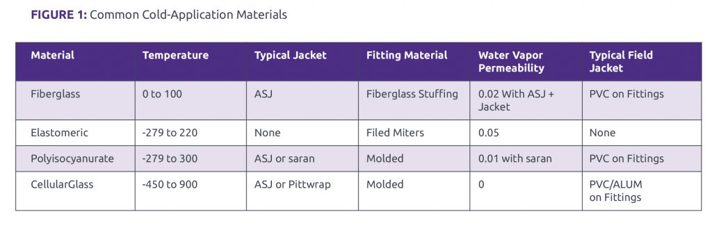
As you can see from Figure 1, the most common insulation materials are compatible with a cold system with the use of a jacket or with a separate vapor barrier. While these barriers have excellent permeability characteristics, it is important to remember that any imperfection in the application of these products can lead to a failure.

While piping comprises the bulk of any chilled-water project, insulation of equipment requires the most time and the expertise of skillful craftsmen. Due to its excellent permeability rating, lack of external jacket, and flexibility to mold around surfaces, elastomeric insulation is sometimes chosen to insulate chilled-water equipment. Used in conjunction with specialized adhesive and a well-trained mechanic, elastomeric is flexible enough to insulate most shapes of the equipment required. Typical applications include pumps, heat exchangers, chillers, control valves, and any point-of-use valves. Other insulations can be used on this equipment as well, but often result in boxed-in equipment, and any maintenance of the equipment could disturb the insulation integrity if they remove or cut into the insulation. Also, elastomeric, polyisocyanurate, and cellular glass do not require a paper vapor barrier jacket, allowing it better durability in equipment rooms while minimizing the cost impact of field applied jacketing like PVC.

Ductwork is another important piece of the insulation envelope for a chilled-water system. The result of a failed vapor barrier in ductwork tends to show itself in the most public spaces of a building. Ceiling structures often point out the failure of insulation with water marks. While these marks can cast a negative image for any office, home, or other facility, water can also lead to mold and added expense for remediation. Cooling coils, diffuser boxes, and flex duct connections are the most common failure points for an air-conditioned system. Maintaining an unbroken vapor barrier and utilizing economical and durable materials are best practices for combatting future condensation issues. Foil-scrim-kraft (FSK) jacketing is the most common vapor barrier utilized for duct insulation and has the same permeability as all-service jacketing (ASJ).

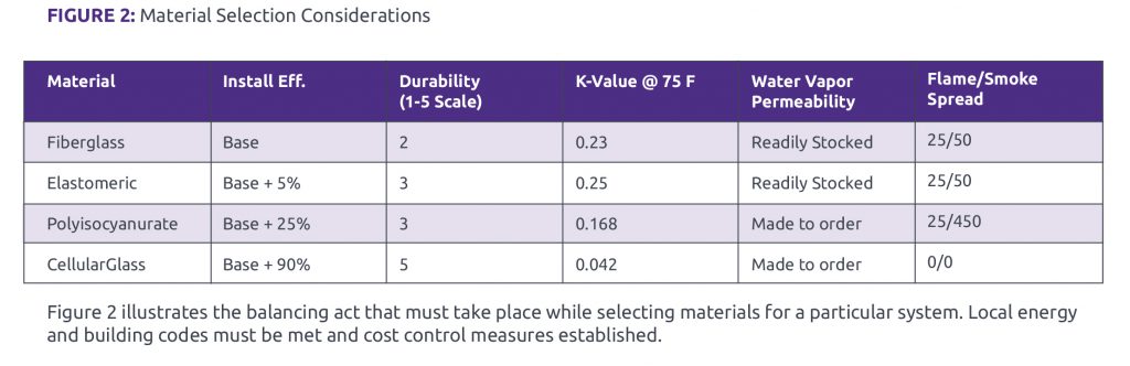
When considering which material is best suited to your needs, cost is often an important factor. It is essential, however, to consider more than a simple side by side of materials. Some of the other factors that deserve consideration are installation efficiency, durability, thermal conductivity (K-Value), availability, and combustibility.

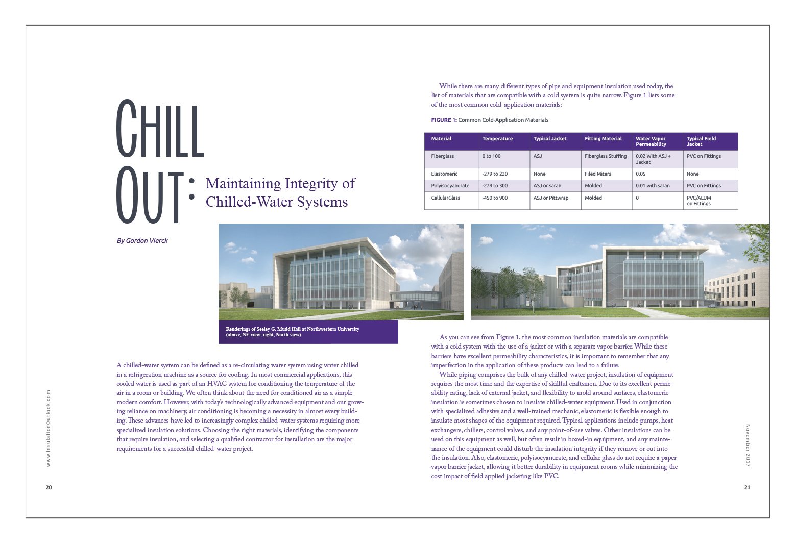
Illustrative Case Study: Seeley G. Mudd Hall at Northwestern University

Luse Thermal Technologies, a mechanical insulation contractor and NIA member company based in an Aurora, Illinois, recently completed work at Northwestern University in Evanston, Illinois, at Seeley G. Mudd Hall, where the University took on an ambitious project to renovate and expand the building to house state-of-the-art scientific research laboratories. This particular project was unique for a chilled-water system because of the varying temperatures and types of chilled water utilized by the research laboratories.

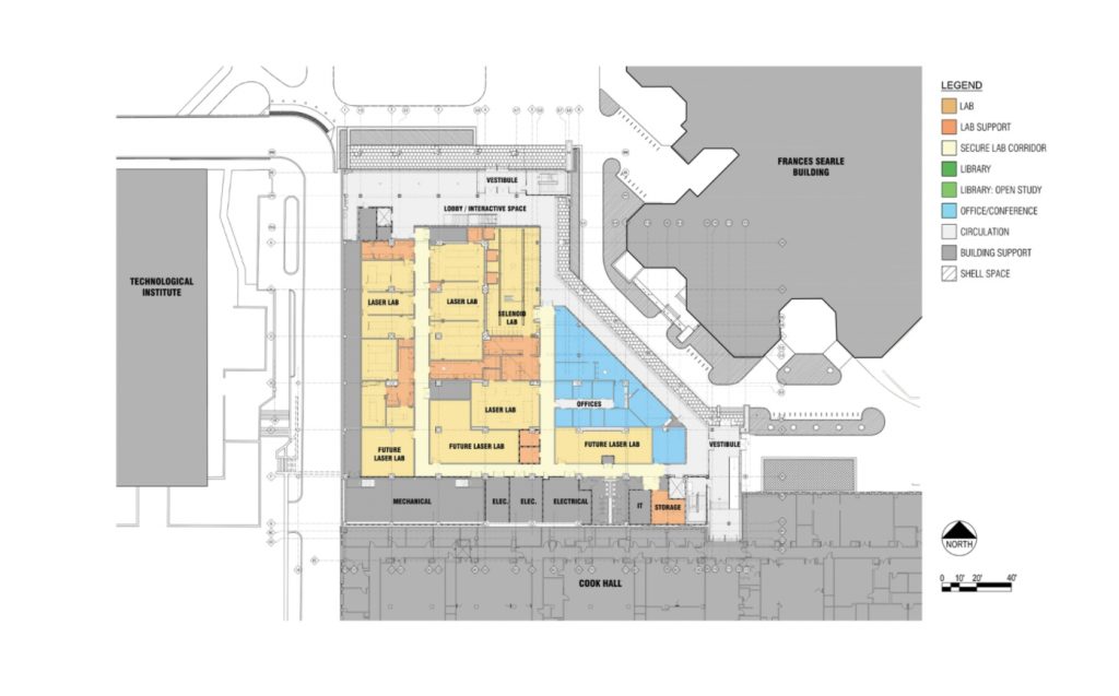
Operating as low as 25°F, chilled glycol lines required polyisocyanurate insulation with saran jacketing. Applying this material can be slow due to its rigidity and molded fittings. In addition, the laboratories utilize process cooling water, chilled water, and secondary chilled water, all requiring varying thicknesses of fiber glass insulation based on their operating temperatures. While the materials and thicknesses varied, the key component to insulating each of these systems was to maintain an unbroken vapor barrier on pipe, specialty valves, and equipment. The contractor also utilized a large amount of elastomeric on the valves and equipment for this project, illustrating the fact that one type of insulation is not best for all situations. The ductwork on this project was fairly standard; since they were supply ducts conveying below-ambient temperatures, they need to receive the same, unbroken vapor barrier as the pipe. This was achieved by using FSK fiber glass duct wrap in concealed locations and ASJ fiber glass board in exposed areas.

A properly insulated chilled-water system should achieve the primary goal of condensation control. Condensation will dramatically accelerate pipe deterioration, create mold on pipe insulation, and possibly damage insulation throughout the system. In addition, wet insulation exponentially decreases its effectiveness. For every 1% of moisture gain, there is a 7.5% loss in thermal efficiency. While we have focused primarily on initial install in this article, note that a maintenance plan for repairing and maintaining your chilled-water insulation integrity should also involve a qualified contractor that meets the same criteria that the initial project required.

While material selection certainly plays a large role in the success of a chilled-water insulation project, the craftsmen installing the products are undeniably the most important component. A skilled insulation contractor will not only deliver peace of mind, but can also finish exposed insulation that will give a mechanical room a polished aesthetic that the owner will be proud to show off. When a mechanical insulation contractor can offer the expertise to recommend materials, properly identify the scope of a project, and provide skilled mechanics to deliver a truly professional installation, success is the natural outcome.


Copyright Statement

This article was published in the November 2017 issue of Insulation Outlook magazine. Copyright © 2017 National Insulation Association. All rights reserved. The contents of this website and Insulation Outlook magazine may not be reproduced in any means, in whole or in part, without the prior written permission of the publisher and NIA. Any unauthorized duplication is strictly prohibited and would violate NIA’s copyright and may violate other copyright agreements that NIA has with authors and partners. Contact publisher@insulation.org to reprint or reproduce this content.

With any product you purchase, it is important to read the label and product data sheet (and assembly instructions, if any) before you purchase it. The data sheet provides you with the physical properties or specifications of the product, defines where or how the product should be used, and details the expected performance of the product. This, in turn, provides you with the information needed to compare competing products and to take performance differences into consideration when evaluating cost differences. For a simple item like a can of soup, you might be looking at calories per serving, sodium content, and whether the soup is gluten, dairy, or soy free. For a riding lawnmower, you may be considering horsepower, transmission type, cutting-deck width, power or manual steering, turning radius, availability of parts and services, and warranty. If you happen to live in California, you need that riding mower to be emissions compliant as well.

In the case of flexible elastomeric closed cell mechanical insulation, the most widely specified standards called out in North America are ASTM C534: Standard Specification for Performed Flexible Elastomeric Cellular Thermal Insulation in Sheet and Tube Form, and ASTM C1534: Standard Specification for Flexible Polymeric Foam Sheet Insulation Used as a Thermal and Sound Absorbing Liner for Duct Systems. These standards define properties such as thermal conductivity, water-vapor transmission, shrinkage, service-temperature range, etc. Life-safety properties like flame spread and smoke developed ratings (also referred to as surface-burning characteristics) are also defined. Each of these properties is determined according to a specific test method, but for many properties, multiple standardized test methods are available and used.

The ASTM standards also establish minimum performance criteria for each of the defined properties. The manufacturer’s data sheets can be used to determine if a product meets the minimum criteria necessary to conform to the applicable standard. The typical insulation product data sheet (or data submittal sheet) also includes information regarding recommended uses and code compliance so that a prospective mechanical engineering specifier or end user can determine whether the specific product is suitable for a particular application (i.e., will it perform to expectation and will it conform to any applicable building codes?). While we are using flexible elastomeric insulation as an example, it is important to note that any insulation product manufactured domestically has an ASTM standard associated with it.

When comparing physical properties of insulation materials, it is very important to compare “apples to apples,” as there may be more than one test method that can be cited for a particular physical property, and the data obtained from different test methods is usually comparable. However, even for that simple can of soup, there are differences that can make comparisons meaningless or misleading to the unwary. As an example, are the calories and sodium content listed per can or per serving? If listed per serving, how many servings are in a can (and are you planning on eating all of it at once)? Variance can make a significant difference, especially if, for instance, there is a health reason for controlling sodium intake.

For example, there are different test methods to determine water absorption. Testing is more complicated than just throwing a sample of insulation in a bucket of water for a prescribed period of time. It makes a difference whether the sample is under 1 inch or 12 inches of water. For many materials with “closed cells,” sample size makes a difference as the ratio of open cells (cut open during the sampling process) to closed cells is greater for a smaller sample than a larger sample. There are even differences in how results are reported. Is it water absorption after 2 hours or 24 hours? Are the results reported as percent weight (mass) gain or percent volume gain?

Likewise, there are numerous test methods that can be used to define the broad category of “reaction to fire.” Within this category, you can find various tests for flame spread, smoke developed, fuel contribution, combustibility, rate of heat release, and ignition characteristics, to name just a few. Some are small scale tests while others are large scale tests, and the results developed from the various tests are not comparable, and often have no correlation. Some tests have multiple results within test methods and these can be more or less stringent, such as with UL94.

In fact, by designing a product to pass one test, the product may fail another test, because they may be measuring contraindicated properties, such as flame spread versus smoke generation. These are somewhat counter to each other in that many flame-retardant additives are known to contribute to smoke generation. Thus, it is very important that if a particular property is called out, you check that the test method used conforms exactly to what is required by the engineer and applicable building code. When it comes to specifications and code compliance, there is no such thing as close enough—or almost no such thing, as explained below.

When comparing products, it is important that the information you are reviewing was obtained using the identical test method and that the test was performed by an accredited testing facility. It is also important that the lab used the latest version of the test method or the specific version as required by the specifier or code body (if different from the current version). Occasionally, it is necessary to deviate from the exact procedure in a test method. When this is the case, all deviations from the standard test must be noted so that a reviewer can determine whether the data can be compared to data for other products using the exact test method.

Continuing with the example of reaction to fire, in the United States, the various mechanical codes require insulation used in plenum areas to meet a 25/50 (flame spread/smoke development index) when tested according to ASTM E84. In Canada, the National Research Council Canada (NRCC), in conjunction with the Canadian Standards Association (which is responsible for writing standards and certifying materials), requires the same 25/50 flame/smoke rating when tested according to CAN/ULC-S102. This is similar to the ASTM E84 test method, but different enough that the results are not interchangeable. Among other differences, CAN/ULC-S102 uses a different air flow rate through the Steiner tunnel and the results calculation methods are different.

While there are European test methods that are intended to measure flame spread and smoke generation, such as EN (European), DIN (German), or BS (British) standards, they are completely different from the ASTM test methods, and would not be comparable. In fact, DIN and BS standards are gradually being phased out in favor of the International Organization for Standardization (ISO) standards.

There are unique circumstances where some of these other test methods may be applicable. While the code may require that an insulation material meet a maximum ASTM E84 25/50 flame/smoke rating, there are alternative means of evaluation available to determine whether a material that does not meet the specific code requirement can meet the intent of the code, in this case to limit the spread of fire in the event that a fire actually occurs. In the United States, this process is usually conducted through International Conservation Code (ICC) Evaluation Services(ES). The ES may consult with experts in the field of reaction to fire to determine what alternative test are necessary and what levels of performance would be required for these tests. Once the requirements are established and the manufacturer satisfactorily completes the testing, ICC ES can issue an evaluation report describing the product, the code requirement(s), the rationale behind the alternative testing protocol, a summary of results, and the conclusion that states that the product tested meets or doesn’t meet the intent of the code. While this is not the same as complying with the code, the evaluation report is generally accepted by code officials who will approve the product based on the guidance offered by the evaluation report.

Testing that provides quantitative results are preferable. Not all tests provide quantitative data and qualitative may be the only type of result available. Using resistance to mold growth as an example:

  • No growth when tested according per ASTM G21 (quantitative).
  • Mold resistance, performance pass when tested per ASTM C1338 (qualitative).

Not all manufacturers will use the same tests or report their findings the same way, but when reviewing a data sheet, one should consider the following:

  1. Be sure the standards cited are relevant to the application and the codes in your country/state or province.
  2. The test methods used and data cited should be up to date.
  3. Be sure the information cited does not confuse standards and test methods. Standards provide performance requirements that the material must meet and the test method that must be used. The test method verifies the performance of the material in line with the requirement of the standard or the test method.
  4. Many test methods define material dimensional characteristics. If the user desires, the material could be tested at the thickness being used to get exact performance results.
  5. When reviewing data for a particular physical property, for a direct comparison, be sure to compare data obtained using the same test method with the results recorded in the same units. Some test method report several results. For example, in ASTM E96, permeance and permeability are both reported but are different properties and may be used for different insulation materials. For thermal conductivity, make sure to compare the same mean temperature against each other (e.g., Product A’s thermal conductivity at 50°F versus Product B’s thermal conductivity at 50°F).
  6. If a manufacturer’s data sheet offers a comparison of performance to other materials, check the data for the other products from their website. Sometimes the comparisons use incorrect or out-of-date data.
  7. Look for what is not on the data sheet. Ask yourself, “why isn’t there any water absorption data or water vapor transmission data on the data sheet for this product?”
  8. If the product uses a facer or requires a vapor barrier, look for the data without the facer or vapor barrier, because this is the performance you could well end up with if the facer or vapor barrier is damaged.

Failure to review a data sheet may result in the following actions:

  1. The installation may be rejected by the local inspector for failure to meet the local building codes and the material may have to be removed, which can be very costly.
  2. The product may not perform as expected in the application.
  3. Increased liability for the specifier, contractor, and distributor.

In summary, information on a product data sheet and reviewing the performance values for desired properties can provide a basis for selecting a material or narrowing the selection of products for a particular application and comparing the performance of multiple products. The data sheet provides all the information needed to ensure the product is acceptable for the application in terms of physical properties and regional code approvals. The information should be specific and detailed, taking much of the confusion out of the product selection process.


Copyright Statement

This article was published in the September 2017 issue of Insulation Outlook magazine. Copyright © 2017 National Insulation Association. All rights reserved. The contents of this website and Insulation Outlook magazine may not be reproduced in any means, in whole or in part, without the prior written permission of the publisher and NIA. Any unauthorized duplication is strictly prohibited and would violate NIA’s copyright and may violate other copyright agreements that NIA has with authors and partners. Contact publisher@insulation.org to reprint or reproduce this content.

The History of Steam Power

Steam power has a long and important history. It has powered an industrial revolution, supported the growth of our largest cities, and shaped the political maps of our world. Yet, for many, it goes unnoticed.  Steam warms our homes and workplaces in winter, and even cools us in summer. Steam also provides the energy to support industrial, medical, commercial, and manufacturing operations around the globe.

Even though steam power has been used since the first century, it really didn’t make its mark on the world until it was used in London in 1698. The idea of harnessing steam power hasn’t changed for centuries, but the technology behind it has. Since the first metropolitan steam network commissioned in New York in 1882, the industry has witnessed incredible technological advances in generation, transportation, and control. Unrelenting demand for quality, reliability, and efficiency have increased the pressure on operators to maintain resilient networks, and the steam community has responded with innovation and advancements. However, even with all the improvements in technology and system design, a key element of today’s steam networks has remained relatively untouched: thermal insulation.

The role of thermal insulation in a steam network is quite simple: maintain the desired steam quality, protect the asset and infrastructure from environmental conditions, and safeguard those who interact with the network, including maintenance personnel and the general public. Those of us in the insulation industry know that when insulation works, it goes unnoticed. When it fails, however, the consequences can be severe.

Insulation may not be the most interesting of efficiency-enhancing measures, but it is the unsung hero in our modern world. Unfortunately, insulation’s contribution to safe and efficient operations is sometimes overlooked in favor of more “advanced” technologies.  Whereas a new, more reliable model of steam trap or a more economical water treatment technology may appeal to a facility manager, insulation choices are largely based on whatever material the site has traditionally used—in spite of the cost of underperforming or failed insulation.

Water is the true enemy of thermal insulation. When insulation becomes wet, it loses its ability to conserve energy, protect workers, and maintain system performance. Thermal resistance is decimated, and the increased risk of corrosion may endanger infrastructure.

A colleague once shared the consequences of saturated insulation in an industrial steam network he had worked on in Europe. It required him to work around periodic reduced capacity and increased condensate production; overloaded steam traps; and increased consumption of fuel, water, and treatment chemicals during winter months. A near disastrous corrosion event on a heavy fuel oil tank roof and wall caused major disruption and expensive repairs. The root cause of the tank performance was corrosion under insulation (CUI), a term that was not well known at the time—he simply believed the tank had failed as the result of wet insulation.

It is critical to keep the insulation system in place and the underlying asset dry. That’s easier said than done, and some facilities have abandoned steam altogether, migrating all or part of their network to pressurized hot water systems. In many cases, this decision is motivated by frustrations born of suppressed capacity, increased maintenance costs, and compromised safety conditions whenever it rains or snows.

Case Study: Insulating Steam Systems at Duke University

Duke University is one of the countless industrial, medical, commercial, and manufacturing operations around the world that generates and delivers steam via an underground network of pipes, vaults, and tunnels. Recently, the university planned to expand its steam supply to a new state-of-the-art medical center; as the University’s Mechanical Engineer, I knew the steam network would need to operate at its highest performance levels to maintain sufficient capacity.

Duke’s steam network consists of approximately 13 miles of underground steam pipe and over 100 vaults. Unfortunately, the vaults were susceptible to severe problems whenever it rained: fugitive steam escaping the vault, boiling water within the vault, damage to the concrete vault structure, and higher operating costs, among other issues.

What caused these problems to the steam system? Wet, damaged, or missing insulation. If a vault is prone to regular flooding, certain insulation materials will not last for extended periods of time. In addition, some thermal insulation materials have a tendency to get crushed when maintenance personnel walk on the piping or work around it.

The option that Duke University chose to mitigate these concerns was a high-temperature aerogel blanket insulation. It is thin, flexible, water-resistant, and breathable. Silica aerogels are amongst the lightest solids known to science, composed of 98% air. Long chains of open celled pores create an intricate path limiting conductive and convective heat transfer. The silica aerogel structure is extremely hydrophobic and has a low thermal conductivity. These features may allow reduced insulation thicknesses to meet local efficiency requirements. Reducing the thickness of insulation in a confined space, such as a vault or tunnel, allows for easier retrofitting or upgrade of steam and condensate lines.

I had experience with this insulation before joining Duke. I had previously tested the product on a project that required the thermal insulation to work in a trench prone to flooding. Despite the challenging environmental conditions, the insulation worked and was successfully integrated into the project, leading me to believe it might also be a good choice for Duke’s steam network.

On the Durham campus, many vaults suffered severe problems whenever it rained, and the existing insulation had previously degraded and fallen off some of the pipework when it got wet. I focused on non-absorbent insulations, and recalling my earlier project, decided to test aerogel blanket insulation in a couple of high-risk vaults. While the layout varies slightly at each vault, the scope mandated upgrades to current campus standards, including installation of inverted bucket steam traps, standardized steam trap assemblies, and the testing or replacing of sump pumps. The insulation was applied to all steam and condensate piping and fittings, and valves were protected with removable jackets.

The results were very positive. Not only did the aerogel blanket survive, but it continued to insulate, contributing to the transformation of the existing network and safeguarding the performance of the medical center addition.

Duke is experiencing numerous benefits from these new insulation systems. Duke has more than 100 steam vaults with various pipe sizes and configurations. The facilities team estimated each vault’s heat loss when fully insulated versus uninsulated: on average, an uninsulated vault costs the university around $4,750/year. When fully insulated, the cost of heat loss plummets to $359/year. Duke budgeted approximately $3,000–$4,000 per vault for installing new insulation, giving the university a simple payback of less than a year. For completely bare vaults, we will see savings up to 92%. While these savings would be true for any insulation (taking into account varying thickness to match the heat loss), the main difference with using a steam-appropriate insulation—such as aerogel—is that it can withstand flooding and remain securely on the pipe, thus saving money and resources that would have been spent on re-installation.

After the first test install, I observed the system and noted there was no steaming, reduced complaints, and reduced maintenance and overtime spending—mainly due to not having to re-insulate the vault after heavy rain or a prolonged period of flooding. We now have less of a problem with sump pumps burning out prematurely due to flooding as the water does not get hot enough to damage the pump.

Insulation is vital to steam networks. Just looking at our energy/cost calculations, it is apparent that a lack of insulation cost us money and increased heat in vaults leads to brittle concrete, excessive wear on sump pumps, and unsafe conditions for entry. Additionally, excessive heat loss can quickly overload the steam traps and our condensate management system, leading to larger problems in distribution. In the past, lack of insulation on the piping had been a contributing factor to excessive condensate build up in the piping—an issue that is now mitigated.

For others in similar situations, I recommend testing the insulation materials in your worst wet environment. While I concede it may cost more to use an insulation that is new to installers (who may have been using the same insulation for decades), it will save money in the long run. I am pleased with the results of the new installation, which allows us to better manage ground-water infiltration and keep our steam system efficient and operational.

After a successful pilot, I changed Duke’s design guidelines for steam vault insulation to use aerogel blanket insulation. Each year, we evaluate the distribution system to see which vaults are least efficient and target them for re-insulation. We have re-insulated all or part of 22 steam vaults and will continue re-insulate 5–10 vaults per year until all the vaults are well insulated and operating as efficiently as possible.

In addition to using it in our steam vaults, we have started specifying this material as the primary insulation in our direct buried piping systems. The reduced insulation thickness reduces the outer diameter of the piping system and ensures the insulation will remain effective should a major leak occur. As a side benefit, the reduced outer diameter has also decreased new vault sizes and trench widths, further lowering installation costs.

Ordinarily, expanding the steam network system for the new medical center at Duke would require additional steam-generating capacity. However, the application of new insulation made the system so efficient, that we do not require this additional capacity investment.

Conclusions

Taking system conditions and likely wear and tear is a critical part of designing an insulation system. In the case of steam systems, it is vitally important to specify an insulation that can withstand the moisture and wear typically associated with these applications. Proper specification and maintenance can reduce energy usage, guard against corrosion, and garner significant financial savings.


Copyright Statement

This article was published in the May 2017 issue of Insulation Outlook magazine. Copyright © 2017 National Insulation Association. All rights reserved. The contents of this website and Insulation Outlook magazine may not be reproduced in any means, in whole or in part, without the prior written permission of the publisher and NIA. Any unauthorized duplication is strictly prohibited and would violate NIA’s copyright and may violate other copyright agreements that NIA has with authors and partners. Contact publisher@insulation.org to reprint or reproduce this content.

How Some Boilerplate Language Resurrects Long Dead Insulation Materials

Is your boilerplate language up to date? When was the last time that you reviewed the insulation materials and system design that you recommend to clients? All too often in mechanical insulation system design specifications, the boilerplate language goes unrevised for long periods of time, even years. Recently, National Insulation Association (NIA) members have reported that they have seen boilerplate language that recommended sewn canvas lagging cloth—a material that has not been used in several decades—and specifications that require the installation of asbestos-containing insulating materials. It is important to ensure you are not copying and pasting old language like this into your brand new project specifications. In a more common scenario, energy codes change and new product technologies are not updated. Are you recommending a system that is not efficient or is already out of date for a brand new “energy-efficient” building? Often the problems that these specifications create are dealt with much further into the project, and you may not even be aware of the changes and adjustments that are being made.

Bad Language Costs Money and Time

Copying and pasting older specifications may make project design easier, but someone will pay for it down the line. Sometimes these erroneous specifications are not noticed until too late, and then cause a delay in the build process. Frequently, it is the insulation contractor who realizes that the specifications are not current or will not work with the job as it is designed; this may happen either during the bidding process or later during the construction phase. The insulation contractor then has to send his or her changes and new recommendations to the mechanical contractor, general contractor, or project manager, who takes it to the field engineer, who may need additional approval. Once everything has been reviewed and approved and that has been conveyed back down the line, the materials still have to be ordered and received before the work can begin. These material purchases and time delays can impact a project or delay the schedule. This easily preventable situation happens far too often, but it can be mitigated by ensuring the
recommendations are done correctly the first time, rather than being corrected after the project has begun.

There Is a Solution

Take a look at your boilerplate language today to make sure you are recommending the best system and materials to meet today’s product advancements and energy regulations and standards. If not, NIA members are always available to review boilerplate language and help you update it. Midwest Insulation Contractors Association (MICA) also suggests that specifiers require insulation contractors to use the insulation system plates found in the National Commercial & Industrial Insulation Standards (NCIIS or MICA Manual) manual to detail the insulation materials and design. These illustrations allow contractors to show the types of insulation and insulation installation accessories to be used during installation and eliminate insulation specification confusion. It can be yet another tool to ensure zombie specifications stay buried and prevent them from wreaking havoc on your project.

Visit www.insulation.org/membership to find a NIA member to help you update your specifications today.


Copyright Statement

This article was published in the October 2016 issue of Insulation Outlook magazine. Copyright © 2016 National Insulation Association. All rights reserved. The contents of this website and Insulation Outlook magazine may not be reproduced in any means, in whole or in part, without the prior written permission of the publisher and NIA. Any unauthorized duplication is strictly prohibited and would violate NIA’s copyright and may violate other copyright agreements that NIA has with authors and partners. Contact publisher@insulation.org to reprint or reproduce this content.

Below-ambient systems create unique environments that have the potential for a multitude of issues, one of which is mold growth. Mold growth can occur either on or in
mechanical insulation on
pipes and tanks if the right conditions are present. When mold grows inside duct work, it can be a very significant issue, and cause for concern. The conditions in ducts
can be conducive for mold growth and the potential for health issues is high, particularly in schools, public buildings, and health-care facilities. Selecting the correct
insulation type and installing it
properly according to industry specifications and the manufacturer’s instructions can significantly decrease the probability of mold becoming an issue.

The Risks of Mold Growth

In the past 15 years, the concern over mold has increased in large part due to lawsuits. Many observers wondered if mold would become the next big industry issue and be
the subject of an
increasing number of lawsuits and other litigation. It is important to remain vigilant about the risks of mold growth. When mold problems arise in the field, the issues
relating to them generally
become the responsibility of the Design Engineer or the Installation Contractor. Correcting a mold problem can cost thousands, if not millions, of dollars. When mold is
found in the walls of a
multi-story condo complex because the insulation on the cold water lines did not perform properly, the cost to repair the damage can be particularly high. If mold is found
in the duct system of a
new elementary school, the cost of remediation can also be very high, but can reduce health risks to the occupants. These real world examples should make every Design
Engineer,
Mechanical Contractor, and Insulation Contractor take the issue of mold very seriously.

Environmental Elements Needed for Mold Growth

To eliminate mold, it is crucial to understand the key environmental elements required for it to form. For mold to form and thrive, 3 conditions must be present: an
environment with an
air temperature within a range typically found in building interiors, the presence of a food source, and the presence of either sustained high humidity or water. The best
way to
attack mold is to eliminate 1 or more of the 3 conditions necessary for its growth. Elimination of the air temperature conditions is usually not an option. Eliminating the
food source can
be difficult, but should be considered. The food source does not have to be the insulation itself, which is often blamed. Rather, it can be the dirt or dust attached to the
insulation, which
is almost always present. One option for reducing the propensity of the insulation to attract or capture dirt or dust is to use a jacket or select an insulation material
that resists dirt
accumulation. However, use of a jacket in a duct liner application is usually not a viable option, so it can be difficult to completely eliminate the dust or dirt that
serves as a food
source in those applications. Another option is the installation of UV lights inside ducts to eliminate mold—though this merely treats the mold rather than
eliminating the source.

Reducing Moisture to Prevent Mold Growth

The most common and tenable option for eliminating mold growth is to reduce moisture. Moisture can exist as either high humidity conditions or as water. Systems that
operate at below-ambient
temperatures have the potential for surface condensation, making them susceptible to mold growth. The use of biocides can be used as a secondary deterrent, but eliminating
the moisture
required for mold growth is the best option. There are several steps that can be taken to eliminate the presence of moisture, which can prevent mold from becoming an issue.
Three key steps are
1) specifying an adequate insulation thickness to prevent surface condensation; 2) selecting insulation materials that do not provide a food source for mold; and 3)
installing the
insulation correctly and maintaining the insulation system.

Step 1: Specifying Proper Insulation Thickness

In a below-ambient system, the first step in preventing mold is specifying a thickness of insulation that will prevent surface condensation most of the time. When
determining this, it is
important to remember that codes or other minimal specified levels of insulation—even for below-ambient lines—are generally developed for thermal efficiency,
not condensation control.
Preventing surface condensation sometimes requires greater thicknesses than those specified just for energy conservation (i.e., usually based on an economic thickness). To
determine design
conditions for unconditioned spaces (i.e., those spaces that are not continuously controlled for air temperature and percent relative humidity), it is recommended that the
designer follows the guidelines given in industry resources such as the ASHRAE 2013 Handbook of Fundamentals, Chapter 23, and the Mechanical Insulation Design Guide.

Step 2: Selecting Mold-Resistant Insulation

Unfortunately, surface condensation cannot be totally eliminated from ever occurring for most systems. Some condensation will probably occur in the rare situations when
the environmental
conditions exceed the design conditions for which the insulation thickness was specified, particularly in unconditioned spaces. Selecting a jacket for the insulation and
specifying an insulation
that inherently resists moisture penetration will reduce the probability of condensation. Using a jacket that incorporates a metal foil in its construction, does not have
exposed
paper on its outer surface, and is sealed tightly at the joints is a good first step.

Selecting an insulation that is resistant to mold growth is the second step in preventing mold and reducing the issues casual condensation creates. Insulations with a
closed-cell structure—such as elastomeric, polyethylene, polystyrene, or cellular glass—are resistant to moisture penetration and have a history of resisting
moisture without the need for an additional jacket. Other insulation materials work well with the proper design, vapor barriers, or jacketing. The best insulation to use in
a specific application (i.e. cold water, chilled
water, refrigeration, duct liner, etc.) depends on the temperature, configuration/shape, and specific requirements of the application. Some insulation materials have a
biocide incorporated in them for added mold resistance. The biocide should be approved by the U.S. Environmental Protection Agency (EPA) for use in ducts (air stream).

There are several test methods used to determine if an insulation or jacket material is “mold resistant.” In all cases, the test methods use clean, dry insulation or
jacket samples, which is
usually not comparable to real world conditions where dirt/dust is nearly always present as a food source. An insulation material’s testing and certification that it is
“mold resistant,” even when tested in accordance with a specific ASTM mold-resistant method, does not guarantee a mold-free installation if other factors are ignored. These
various tests and mold-resistant certifications may be useful, however, when comparing different insulation materials—while insulation cannot be guaranteed to be mold
free, some materials may fare better than others. When comparing
insulation materials, the same exact test method should be used for the basis of comparison. There are several third-party laboratories that certify products as being mold
resistant and are often
cited on insulation material product data sheets.

Step 3: Properly Installing and Maintaining the Insulation

Installing the insulation and establishing a proper maintenance plan is the third step in preventing mold in a below-ambient system. The insulation materials being
installed should be dry,
and should have never been exposed to water. The building should be enclosed (i.e., not exposed to the elements), which limits the potential for the insulation being
exposed to water once
it is installed. In addition, when installing insulation on an HVAC system, the system should not be running and the piping and ducts should be dry. While installing the
insulation, it is
mandatory for the installer to maintain the integrity of the insulation system for proper performance. Sealing all seams (butt, longitudinal, and termination points) is
mandatory for
below-ambient applications. Some insulation materials, such as flexible elastomeric and polyolefin, may use a contact adhesive rather than a tape to seal the seams. If the
insulation
becomes damaged (tears, holes, cuts, etc.), it must be repaired in a timely manner. Damaged insulation can lead to the degradation of the insulation on the whole system. It
is ideal, and less
costly, to both design the application properly and install it according to the manufacturer’s instructions than it is to make the repairs after it is installed.

Following the aforementioned steps and making everyone working on the project aware of mold as a potential problem can often prevent it from occurring. The key to
preventing mold
growth is simple: keep it clean and dry. Effective condensation control to eliminate the presence of water is not a matter of chance, compromise, or cost minimization. From
the beginning of the
project, it requires clear communication among all parties involved and clear instructions on what is expected of them. While some condensation may occur when environmental
conditions exceed the
design conditions for which the insulation is specified, it is possible—with proper planning, materials, and maintenance—to materially lessen the chance of
condensation and the
conditions that may lead to mold growth.

Adhesives

A variety of adhesive types are
available for many different
applications, including insulation attachment, insulation-fitting fabrication, and facing. Adhesives are available in water-based, solvent-based, hot
melts,
reactive-cure, pressure-sensitive, and aerosol formulations. These adhesives can be applied through
numerous methods, including brush, spray, trowel, and roll coater. When selecting an adhesive, the insulation
type, service-temperature limits, application method, and required adhesive strength should all be considered. Refer to the adhesive manufacturer’s
product
selection guides for assistance in choosing adhesives for specific uses. In all cases, regardless
of the type of adhesive used to secure the insulation, it is important to prepare the surface being adhered to. It
must be free of dirt, rust, loose particles, and oil. Wiping the surface with denatured alcohol is often
recommended. Ambient and surface temperature are also important considerations when selecting an
adhesive. When considering ambient temperatures, it is essential to factor in the temperature over the entire curing time. The surface being bonded to
must also
be considered. Steel (coated or painted), plastic (such as polypropylene), or others, may require
special preparation work or adhesives.

For attachment and fabrication, rigid insulations will usually require thicker, high-bodied adhesives capable
of filling small gaps, while flexible insulations such as fiberglass, mineral wool, or elastomeric use thinner
adhesives with a higher coverage rate. Attachment or fabrication of impermeable insulations will require contact,
pressure-sensitive, or reactive-cure adhesives to avoid trapping vapors. Water-based adhesives are not recommended. When using contact adhesives, it is
important
to coat both surfaces with a thin coat of adhesive (a thin coat is better than a thick coat),
and to allow the solvents to evaporate before combining the 2 surfaces. This may vary with installation conditions (temperature and humidity). When
using pressure-sensitive adhesives, it is important to apply pressure to ensure the adhesive is wetted out between the 2 surfaces being adhered. As the
installation
temperature gets colder, the amount of pressure to wet out the adhesive increases.

Other specialty adhesives include cryogenic adhesives for very cold operating systems (down to -320°F), and high-temperature inorganic adhesives for
hot work (up to 800°F). When used for attachment, most adhesives are used in conjunction with mechanical fasteners.

Duct-Liner Adhesives

Duct-liner adhesives include water
and solvent types as well as pressure-sensitive adhesive and hot melts. They
can be applied in a sheet metal shop
either as part of a coil line or on
fabrication tables. Typical duct-liner
specifications require 2 forms of
attachment; generally, weld or stick
pins and an adhesive are used. On coil
lines, the adhesive is often water based
to allow for immediate weld-pin
placement without concern for flash
fire. Water-based adhesives do not work
well with closed cell foam duct-liner
materials because the water cannot
evaporate. Hot melt, spray adhesives, or
pressure-sensitive adhesives are often
used on these products.

Reinforcements for Cements and Mastics

Reinforcing fabrics for cements and mastics are critical to prevent cracking over seams or areas of movement, and to improve the overall strength of the finish. They come in a variety of types
and sizes. The reinforcement chosen must be of the correct type and size, and be compatible with the mastic or cement to ensure proper function. Refer to the mastic or cement manufacturers’ product
data sheets for compatible reinforcements. Fiber fabrics include open-weave fiberglass, synthetic fiber meshes, woven canvas, and fiberglass cloth. Mastics are typically reinforced
with 10″ x 10″ open-weave cloths for most applications. Heavier duty 5″ x 5″ mesh cloths are sometimes used with heavier coats of mastics. Reinforcements should always be embedded within the wet
mastic or cement and be fully covered. All seams in the fabric should be overlapped by a minimum of 2 inches to avoid the potential for cracking.

Sealants

Sealants can be broken up into the following general categories:

  • Duct sealants
    • Sheet-metal sealants
    • Duct-board sealants
  • Flashing sealants
  • Joint sealants

Duct Sealants

Duct sealants come in a variety of formulations. Typically the sealant is a high-bodied water or solvent-based formulation applied by brush or cartridge gun. UL-181 A-M for duct board
and UL-181 B-M for flexible and rigid metal duct give standard requirements for duct sealants that may be used to specify them. Metal ducts should also
meet the Sheet Metal and Air conditioning Contractors National Association (SMACNA) pressure standards for the duct system being sealed. Refer to the duct sealant manufacturer’s
product data sheets and material selection guides for more information.

Flashing Sealants

Flashing sealants are used to seal insulation terminations, penetrations, and protrusions that occur around valves, gauges, and other areas where the insulation is broken. They may also
be used to seal metal-jacketing seams. Flashing sealants protect the exterior of the insulation system from the ingress of liquids or vapors. The flashing sealant must be compatible with
all the surfaces it comes in contact with, including the insulations and insulation finishes. It should be applied per the manufacturer’s instruction in order to create a
watertight seal.

Joint Sealants

Joint sealants are used to seal the longitudinal and circumferential butt joints of rigid insulation against moisture penetration. Joint sealants are
of
particular importance in cold-temperature systems to lock out water
vapor penetration between blocks of insulation. Joint sealants are made using high solids and are available in a
variety of types. The joint sealant should remain flexible after application to allow for movement in the insulation
system without cracking or splitting. Selection of the proper joint sealant will depend upon the operating
temperature at the point where the sealant is applied, the insulation type being sealed, and the finishes being
applied over the top of the insulation. Refer to the manufacturers’ product data
sheets and product selection guides for more information on the selection and application of joint sealants.

Other Accessory Products

There are a wide variety of additional accessory products required for successful installations of
mechanical insulation, including:

  • Securements
    • Studs and pins
    • Staples, rivets, and screws
    • Clips
    • Wire or straps
    • Self-adhering laps
    • Tape
  • Flashing
  • Stiffening
  • Supports
    • Heavy-density insulation inserts
    • Pipe-support saddles and shoes
    • Wood blocks and dowels
    • Pre-insulated pipe supports
  • Caulking
  • Expansion/contraction devices

These accessory products are readily available from a number of vendors.

Product Characteristics of Weather Barriers,
Vapor Retarders, and Finishes

Fabrics are often
coated and used as insulation jacketing materials, particularly for
removable/reusable insulation covers. The fabrics are woven from a wide variety
of textile fibers including, but not limited to:

  • Canvas

  • Fiberglass (Type E)

  • Amorphous silica fibers

  • Ceramic fibers

  • Aramid fibers

  • Stainless steel

  • Inconel

Coatings and laminate
membranes are usually applied to these fabrics to provide increased protection
and abrasion resistance. Common coatings include, but are not limited to:

  • Acrylic

  • Silicone

  • Polytetrafluoroethylene
    (PTFE)

  • Polychloroprene

  • Vermiculite

The selection of the
fabric/coating combination for a particular application depends on the
temperature, abuse, chemical compatibility, and combustibility requirements.
Consult manufacturers of fabrics or removable/reusable covers for guidance.

ASHRAE, founded in 1894 (and formerly known as the American Society of Heating, Refrigerating, and Air Conditioning Engineers), is one of the largest engineering groups in North America, with more than 54,000 members worldwide. The group and its members focus on building systems, energy efficiency, indoor air quality, refrigeration, and sustainability within the industry. ASHRAE’s mission is to advance the arts and sciences of heating, ventilating, air conditioning, and refrigerating through research, standards writing, publishing, and continuing education.

ASHRAE Publications
The well-known Standard 90.1—which contains standards for the energy-efficient design of high-rise residential, commercial, and institutional buildings—as well as Standard 55—on thermal comfort standards in buildings—are periodically revised. In recent years, Standard 90.1 has been revised every 3 years and is referenced by its year of issue: 90.1-2004, 90.1-2007, 90.1-2010, and 90.1-2013. Standard 90.1 was first published in the mid-70s. ASHRAE publishes 4 Handbook volumes: Fundamentals, Refrigeration, HVAC Applications, and HVAC Systems and Equipment. Each volume is updated every 4 years. The ASHRAE Handbook—Fundamentals was published in 2001; 2005; 2009; and, most recently, in June 2013. The ASHRAE Handbook—Refrigeration was published in 1998; 2002; 2006; and, most recently, in 2010. The 2014 edition has been approved and is being type-set for printing and distribution in June 2014. There are many other ASHRAE publications, such as copies of technical papers presented at the semi-annual meetings. They also publish many books; 2 examples are The ASHRAE Guide for Buildings in Hot and Humid Climates and the ASHRAE Green Guide: The Design, Construction, and Operation of Sustainable Buildings.

ASHRAE Standard 90.1-2013
ASHRAE recently released the latest edition of Standard 90.1, entitled Energy Standard for Buildings Except Low-Rise Residential Buildings. This standard addresses high-rise residential, commercial, and institutional buildings (i.e., not single-family residences or low-rise apartments). It has sections on minimum requirements for the building envelope, fenestration (i.e., windows and doors), service water heating, power, lighting, and HVAC (including mechanical insulation). A major goal of issuing periodic revisions to Standard 90.1 is to make improvements in reducing building energy use. Hence, the 2013 edition, if followed for a new building design, will result in at least 50% less energy use, by design, than the 2004 edition (with the 2007 and 2010 editions each successively leading to less energy use than the previous edition). This is done by requiring, among other considerations, greater roof and wall R-values; greater use of triple-glazed windows; more reflective window glass; more tightly sealed envelopes; more efficient HVAC equipment; greater use of heat exchangers for ventilation; better control over fresh air ventilation dampers and fans; more energy-efficient lighting (with controls to turn lights off when not needed); and, of course, greater mechanical insulation thicknesses and R-values.

Minimum required insulation thicknesses and R-values for pipe, equipment, and ducts were increased in the 2010 edition over the 2007 edition, but there are no changes in this area in the 2013 edition over the 2010 edition. While this may seem to be an oversight on the part of Standard Projects Committee 90.1, it may instead reflect the requirements in the HVAC section for greater use of lower temperature hot water systems for space heating (i.e., most hot water heating systems operate with a maximum supply water temperature of about 180°F in the coldest weather, and that adjusts downward in milder weather by using electronic controls). In addition, old-style steam heating systems—that often have operating temperatures up to 380°F—are being replaced in both old and new buildings with hot water distribution systems, even if steam is sent to the building from a central steam plant (as is often done at colleges, universities, and hospitals). ASHRAE 90.1-2010 requires insulation with a certain K-factor performance to be applied at a thickness of 5 inches on pipes with an operating temperature greater than 350° F, and a diameter greater than 3/4 inch NPS. In these circumstances, meeting this requirement with mineral fiber insulation requires a double layer.

2013 ASHRAE Handbook—Fundamentals, Chapter 23
Chapter 23 in the ASHRAE Handbook—Fundamentals covers “Insulation for Mechanical Systems.” The 2005 version was the first ASHRAE Handbook—Fundamentals edition with a chapter on this subject, so the 2013 edition is only the second revision of that original chapter. The following is a list of major changes to that chapter in the 2013 edition:

  • Recommended minimum pipe insulation thicknesses, for both hot and chilled pipes, were increased to match those in Standard 90.1-2010.
  • The section called “Condensation Control” was rewritten to better explain how to accomplish the following in regard to chilled water (CHW) pipe:
    • Calculate pipe insulation thickness to minimize surface condensation in unconditioned spaces such as mechanical rooms and central chiller plants, and
    • Minimize moisture intrusion problems in the insulation on those pipes.
  • The section on “Corrosion Under Insulation” (CUI) was updated to explain how to minimize CUI problems and includes recommendations for the use of weather barrier jacketing on outdoor systems.
  • The updated “Materials and Systems” section now recommends the use of lower permeance insulation systems on CHW pipe and equipment systems, and use of appropriate weather protection on outdoor systems.
  • The subsection on vapor retarders now urges caution when using traditional All Service Jacket (ASJ) on CHW systems in unconditioned spaces, particularly when the building is located in a region with a hot and humid climate. In the same subsection, there are new recommendations to use appropriate vapor retarders on CHW pipes.
  • The “Installation” section added advice on the design of factory-insulated pipe supports. The section also includes new information advising designers and building owners to pay particular attention to pipe components in mechanical rooms (such as valves, flanges, strainers, etc.) that need to be insulated along with the pipes. They also need regular maintenance, since that insulation is often stripped by mechanical maintenance personnel.
  • The updated edition includes findings of Research Project RP-1356 on a method of testing CHW pipe insulation and the increased thermal conductivity of pipe insulation with a condensed water content.

2014 ASHRAE Handbook—Refrigeration, Chapter 10
ASHRAE’s TC 10.3 – Refrigeration Piping, Controls, and Accessories has responsibility for the chapter in the 2014 ASHRAE Handbook—Refrigeration entitled “Insulation Systems for Refrigerant Piping,” with a scope that it “is a guide to specifying insulation systems for refrigeration piping, fittings, and vessels operated at temperatures ranging from 35 to -100°F. It does not deal with HVAC systems or applications such as chilled-water systems.” The 2014 Handbook is not yet published, but all revisions have already been approved. The major changes that were approved by TC 10.3 are:

  • An increased emphasis on the need for the vapor retarder system to be continuous
  • Explanation that water entering an insulation system can bring with it a near-inexhaustible supply of corrosive contaminants from the ambient environment, which can exacerbate corrosion.
  • Changes to all the insulation thickness tables to:
    1. Determine all insulation thicknesses using the current state-of-the-art calculation methodology (ASTM C680-10).
    2. Use the latest thermal conductivity curves from the appropriate ASTM material standard for each insulation material.
    3. Maintain the same design criteria used in the 2010 Handbook—Refrigeration (i.e., condensation control and 8 Btu/hr-ft² heat flux limit).
    4. Continue the practice of not including any safety factor in the condensation control calculations.
    5. Use the correct emittance for aluminum jacketing of 0.1, as specified in ASTM C1729-13, Standard Specification for Aluminum Jacketing for Insulation, instead of the 0.4 value used in the past.
    6. Maintain the same design conditions used in the 2010 Handbook, except for changes in relative humidity and jacket emittance.
    7. Minimize the changes from the 2010 Handbook to insulation thicknesses in the tables, since the insulation thicknesses in the current tables have proven to be acceptable in the field. To accomplish this goal for the outdoor condition tables, the design relative humidity was increased until the overall insulation thickness changes to the tables were minimized. This occurred at a relative humidity of 94%, not the 90% previously used. For the indoor tables, the heat gain portion of the design criteria controls the required thickness, so increasing the relative humidity would have no impact. Since the 8 Btu/hr-ft² heat gain limit is firmly set in the industry, it was deemed inappropriate to modify this design criteria. The insulation thicknesses in the indoor tables were therefore allowed to deviate based on only goals 1-4 above.

ASHRAE Research Related to Mechanical Insulation
ASHRAE sponsors a large number of research projects on HVAC-related topics, one of which is ASHRAE Research Project RP-1356 (mentioned in the ASHRAE Handbook Fundamentals section). Dr. Lorenzo Cremaschi, of Oklahoma State University (OSU), gave a presentation on this project at the National Insulation Association’s (NIA’s) 2013 Annual Convention. That project is complete and will be featured in an upcoming issue of Insulation Outlook. The full report is also available for purchase from ASHRAE’s online bookstore for $30. Another project—RP-1550, conducted by David Yarbrough—addresses the thermal performance of thermal insulating coatings. That project was also recently completed and is going to be featured in an upcoming issue of Insulation Outlook. The full report is available for purchase through ASHRAE for $30. In this project, 3 commercially available coatings were tested using an ASTM C335 hot pipe test apparatus.

Finally, OSU is currently conducting another research project, RP-1646, using the same test facility it developed as part of RP-1356 (i.e., an environmental chamber with 2 identical chilled thermal test pipes, 1 pipe being used for moisture condensation test samples, and the other for thermal measurements). OSU is testing 6 different insulation systems for thermal and moisture performance. The pipe temperature for these tests is 38°F, located in an environmental chamber held constant at 90°F and 83% relative humidity. Additional test conditions include:

  1. Flexible elastomeric insulation with all joints glued together and no separate vapor retarder jacket;
  2. Cellular glass insulation with all joints sealed and no separate vapor retarder jacket;
  3. Fiberglass jacketed with standard ASJ and sealed with standard taped butt and lap joints;
  4. Same system as number 3, with the addition of solvent sealed PVC jacket;
  5. Polyisocyanurate insulation covered with PVDC film, with taped butt and lap joints; and
  6. Phenolic foam insulation covered with a very low permeance vapor retarder jacket and tape, with a pressure-sensitive adhesive, which both meet ASTM C1136, Type IX.

Since each system must be tested for 2 months’ duration, progress is slow. The first couple of tests had to be repeated due to irregularities that were discovered. Hence, this research project may not be complete, with a test report reviewed and approved by TC 1.8, until late in 2014 or early 2015. When completed, each system will have been characterized by a tested system vapor permeance and a relationship, for the insulation material, between condensed water content and thermal conductivity at a below-ambient temperature.

SIDEBAR:
What Does ASHRAE Do?
Among other matters at the society-wide meetings, the Technical Committees (TCs) meet to discuss their objectives and projects. Three such groups are: TC 1.8 – Mechanical Systems Insulation, TC 10.3 – Refrigerant Piping, and TC 1.12 – Moisture Management in Buildings. The TCs are responsible for certain chapters in ASHRAE’s 4-volume Handbook; and they sponsor research, technical sessions, seminars, and forums at the society-wide meetings. There are also a number of Special Project Committees, many of which write standards.

Product Characteristics of Weather Barriers, Vapor Retarders, and Finishes

Laminates are, in general terms, materials made by bonding (through the use of  heat, pressure, adhesives, or any combination thereof) 2 or more layers of materials. The layers can be comprised of similar or dissimilar materials. Laminates used for protective jacketing may be comprised of metal foils, plastic films, papers, nonwovens, scrims, etc. and may or may not contain a topcoat of some kind for coloration or UV resistance. Laminates may also come in a variety of different configurations.

For vapor retarder applications, at least 1 component must be a material that offers significant resistance to vapor passage. Laminates may be classified into 3
categories:

  • Laminated Foil Jacketing (ASJ/FSK/PSP/PSK)
  • Synthetic Rubber Laminates
  • Multi-ply Laminates

Laminated Foil Jacketing (ASJ/FSK/PSP/PSK)

A traditionally used pre-formed jacket for pipe, tank, and equipment vapor retarder applications is the lamination of white paper, reinforcing fiberglass scrim, and aluminum foil.

This laminate is typically called All-Service Jacket (ASJ). Variations on this structure, sometimes referred to as Next Generation ASJ, is a similar basic structure, with a white polymer film/substrate in place of the bleached paper. These products are generally referred to as ASJ or next generation ASJ  and meet the requirements of ASTM C1136, Standard Specification for Flexible, Low Permeance Vapor Retarders for Thermal Insulation.

Traditional ASJ or next generation ASJ facings are commonly used as the outer finish in low abuse, indoor areas; elsewhere, they are covered by a protective metal or plastic jacket.

A similar facing material, foil-scrim-kraft (FSK) has the same basic structure except with the aluminum foil layer facing outward. Numerous variations, such as Poly-Scrim-Poly (PSP) or Poly-Scrim-Kraft (PSK), are also available. Many types of insulation products are supplied with factory-applied ASJ, FSK, or PSK vapor retarders.

Synthetic Rubber Laminates

Synthetic, rubber-based laminates typically consist of aluminum facing laminated to a synthetic rubber membrane and a peel-and-stick application. These laminates are used on pipes, ducts, and tanks for both interior and exterior applications, and may be used in direct burial applications. A variety of weights are available. Perm values of less than 0.02 are reported, and the materials are generally considered to be “self-healing” in that small
punctures and penetrations will re-seal.

Multi-ply Laminates

Multi-ply laminates consist of multiple layers of aluminum with alternating layers of polyester or polyethylene film with a peel-and-stick adhesive system. These laminates are used on pipes, ducts, and tanks for both interior and exterior applications. They cut easily and install easily in the field. Perm values of 0 or near 0 are reported. They are available in smooth or embossed surface finish in a variety of thicknesses. Several colors and chemical-resistant films are also available.


Copyright Statement

This article was published in the January 2014 issue of Insulation Outlook magazine. Copyright © 2014 National Insulation Association. All rights reserved. The contents of this website and Insulation Outlook magazine may not be reproduced in any means, in whole or in part, without the prior written permission of the publisher and NIA. Any unauthorized duplication is strictly prohibited and would violate NIA’s copyright and may violate other copyright agreements that NIA has with authors and partners. Contact publisher@insulation.org to reprint or reproduce this content.

Product Characteristics of Weather Barriers, Vapor Retarders, and Finishes


Polymeric (plastic) rolls or sheets are available at various
thicknesses. These materials are glued, solvent welded, or taped depending on
the polymer. Elbows and tees are also available for piping for some type of
polymers. Typical polymeric (plastic) jacketing materials are:

  • Polyvinyl Chloride (PVC)

  • Polyvinyliedene Chloride (PVDC)

  • Polyethylene Terephthalate (PET)

  • Polyvinyl Flouride (PVF)

PVC Jackets

PVC
jackets are made of a durable, attractive, and easy–to–clean material that is
typically field–applied over unfaced insulation and most factory–applied
jackets where additional protection is necessary. PVC jackets are covered by
ASTM Standard Practice C921–10, Types I and II, Grade 4.

PVC
jackets are available in several thicknesses and colors. Standard thicknesses
are 10, 15, 20, 30, and 40 mils, with 20 and 30 mils being the most common
thicknesses. Thicknesses of 30 mils are recommended for outdoor applications.
Jacketing meant for outdoor use should be UV stabilized. While PVC jacketing is
usually white, jackets are available in a variety of colors (colored jacketing
is normally not available with UV stabilization).

Several
manufacturers and fabricators offer PVC “cut and curl” jacketing products.
Fitting covers are also available for covering elbows, tees, valves, flanges,
mechanical couplings, drain bodies, strainers, end caps, and other common
piping products. Accessory products (solvent adhesive, tapes, stainless steel
thumbtacks, etc.) are also available from manufacturers.

PVC
jacketing up to 30 mil thicknesses generally meet 25/50 flame–spread and
smoke–developed indexes. Jacketing temperatures should be kept below 150°F for
hot services. PVC jackets can be used in areas requiring frequent washdown and
are used extensively for applications requiring USDA and FDA approval. To
achieve USDA and FDA approval, PVC jackets should be installed with continuous
solvent welded joints and seams. PVC jackets and fittings, when applied over an
intermediate vapor retarder and properly sealed, can be used on cold systems.

PVDC
Film

PVDC Film
is a flexible and tough vapor–retarder facing that is applied to the exterior
of pipe, vessel, and equipment insulation systems. This vapor retarder consists
of a biaxially oriented homogeneous opaque white polymer film. It can be
factory or field applied to the surface of the insulation and is available in 2
thicknesses, 4 and 6 mils, both at 35.5″ wide and more than 250 feet long. When
factory applied to insulation, the lap joint of the vapor retarder is sealed in
the field using a self–sealing lap (SSL). The PVDC tape is the same type of
homogeneous white film to which an adhesive backing which does not require
release paper, has been applied. The tape is available at 2 and 6 mil
thicknesses; widths of 1″, 2″, and 3″; and 150 feet length. PVDC films are not
intended for exterior applications unless protected by a suitable weather
barrier.

ASTM
Standard Specification C1136–10, Types VII  and VIII covers this type of
vapor–retarder facing for use where insulation outer surface temperatures are
–20 to 150°F. This ASTM standard specification establishes requirements for
permeance, burst strength, tensile strength, dimensional stability, flame/smoke
performance, zero fungal growth, and lack of cracking or delamination.

ASTM
Standard Practice C921–10, Type II, Grade 4 covers this type of film for use as
a vapor–retarding outer jacket on thermal insulation over mechanical equipment
such as tanks, pipe, and vessels. The 6 mil PVDC film meets the permeance
requirements of Class A, “Extremely low permeance” or 0.01 perms maximum. The 4
mil PVDC film meets the permeance requirements of Class B, “Very low permeance”
or 0.02 perms maximum.

Key
applications for PVDC vapor retarder is in insulation systems for pipe,
equipment, tanks, and ducts—especially those operating at temperatures below
ambient such as food and beverage lines, refrigeration, ammonia refrigeration,
and liquid natural gas (LNG) pipe. PVDC film is applied to the insulation on
straight sections of pipe or to large surfaces like tank or duct walls. PVDC
tape is used to seal joints in the film, at vapor retarder butt joints on pipe
insulation, wrapped around complex insulation shapes such as fittings and
elbows, and can be used to repair physical damage to the vapor retarder film.