Category Archives: Global

The goal of a good logistics system is to bring in product, track the product while it is in your possession, and ship it to the customer in a timely and accurate manner. The goal has not changed over the years, but the tools and programs available to perform this task have dramatically improved and will continue to be refined in the future. An inventory-management system combines the use of desktop software, barcode scanners, barcode printers, etc. to streamline the management of inventory—from raw materials, to work in process, to finished goods being shipped. Whether you are tracking inventory used to manufacture a product or reselling a product, using an inventory system provides accountability and minimizes inventory stock-outs and shrinkage. This article will give an overview of what questions one should ask before implementing a new program and how the program should ideally interact with all phases of an operation—from raw material tracking to shipping and delivery of finished goods. The article will focus on Adage ERP by Infor (which has many features common to most systems used by medium-sized manufacturing companies).

A well-designed inventory-control system provides easy access and accurate information based on manual input. If the input is not accurate, the information will not be useful. Good inventory-control techniques and timely cycle counts are critical. Warehouses should be clean and dry (racked preferred) and use a first in, first out (FIFO) inventory (rotation) system that maintains the physical condition of inventory in good condition. All the foundational elements of a solid inventory-control system are necessary for the new computer-based programs to work properly.

When it comes to implementing the new system, you will need a dedicated team with a knowledgeable team leader who is flexible and a problem solver. The people on this team should have hands-on experience to ensure all the operational requirements are covered. The best systems require a well-coordinated team effort.

There are hundreds of inventory-control programs available. Most of the better and more comprehensive inventory-control systems work as part of an Enterprise Resource Planning (ERP) system. Some of the most well-known ERP systems are SAP, Microsoft Dynamics ERP, Great Plains (GP), M3 by Infor, and Adage ERP by Infor. All software systems have their strengths and challenges. The goal is to pick the one that best suits your company processes.  Consider the following questions when choosing a program.

  • Are you a production site or a warehouse operation?
  • Do you produce products on a continuous basis or a diverse/one of a kind/short-run process?
  • Do you have multiple locations (e.g., satellite warehouses)?
  • Are you supplying to multiple job sites in the same area or are they located nationwide?
  • Do you need to track inventory shipments or freight?
  • Are you a large, medium, or small company?
  • How much program support will you need?
  • What are your cost limitations?

The above questions will help you find the program best suited and at the right price point for your company.

IO160802_01

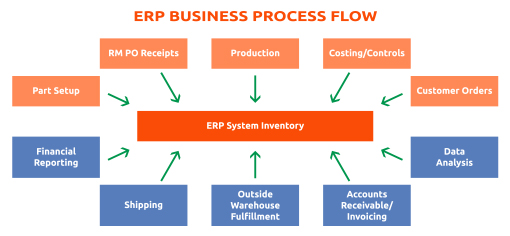
At our company, Adage ERP has worked well for our needs. It allows us to follow the life cycle of our business from customer setup, pricing, order entry, order fulfillment, scheduling, manufacturing, printing bar code labels, shipping, cycle counts, and invoicing. The heart of any good ERP system is keeping data in the system current at all times and the ability to accurately track the movement of goods while maintaining an accurate inventory through the processing of order receipt and shipment to the customer. Essentially, this entails tracking 2 main functions: receiving (incoming) and shipping (outgoing), which allows you to make smarter inventory decisions. The system has improved our order entry process, reduced understock and overstock situations, eliminated data entry errors through scanning, facilitated efficient cycle counting of the entire warehouse, and given us the ability to share inventory data.

When determining if a specific system is best for you, consider:

  • How easy is it to enter a new part number?
  • Can the system handle multiple product configurations?
  • Can prices be changed easily?
  • How much system flexibility do you need?

We also use a system that allows more streamlined functionality with Adage called ASSISTics by A.S.S.I.S.T, Inc. ASSISTics allows us to integrate Adage into our receiving/shipping/tracking capabilities. Customers can track shipments and we can trace products back through the manufacturing process to our raw materials.

Our business outgrew the previous in-house custom designed system. The new system improved our ability to enter orders, respond to customer questions regarding orders immediately (because the information is readily available), and share inventory information between functions in the organization.

The ASSISTics inventory-management system works as follows:

  • Order is entered into the system;
  • The stock inventory is reviewed to determine promised ship date;
  • Incoming raw material barcode is scanned;
  • Bin location is assigned for raw material;
  • Raw material bar code is scanned and product relieved from inventory as it is used in the manufacturing process;
  • Work in process is scanned at each step in the process and eventually scanned into finished goods inventory, at which point a bin location is assigned;
  • Inventory is relieved when product is shipped;
  • Relieved inventory triggers production schedule, which triggers raw material purchases based on minimum/maximum inventory levels and delivery time from vendors;
  • Cycle counts are conducted using bar code scanners;
  • If there is a problem in the field, using the lot number associated with the product shipped, we can trace the product back through the process to the raw materials used; and
  • Inventory data is updated continuously.


In addition, there are consulting companies that can assist in many of the purchasing, inventory control, and logistics issues associated with any operation. There are also Third Party Logistics (TPL) companies that will support review of your freight bills for overbilling.

Distributors

Inventory control at the distributor level can vary from a manual system to something more sophisticated. A distributor purchases in full carton quantities, but breaks the cartons down and sells product by the piece. In order for the distributor to use a bar code system, each piece would need to be bar coded. Thus, a manual inventory-management system is most common for a distributor. To determine what they should have in inventory depends on the ability of the manager to know his territory (e.g., markets being serviced, local building codes, customer preferences, etc.). Each territory will be slightly different. Success will not be measured by never running out of the highest-selling items, but by never running out of the slower movers that are needed from time to time to finish a job. Inventory is managed by daily or weekly cycle counts for inventory accuracy. Historical data is useful, but changing market conditions and even the weather can affect what is needed on hand at any given time. The key to a distributor maintaining accurate inventory is everyone being disciplined. The greatest and most expensive system will fail without a high level of discipline; it takes a team effort.

Jobsite Inventory Control

Inventory control at a job site creates additional issues not found in a fixed-location site operation. First, there is seldom any space to store materials, even on large jobs. As a result, there may be 2–3 deliveries a day, mostly coming directly from the distributor (more than 80% direct shipments) to maintain a couple days’ worth of inventory of materials on the job site. The contractor will usually hold limited inventory in his warehouse for emergencies or fabrication. Materials coming in will be checked against the pick tickets for accuracy. Later the pick tickets will be checked against the material quoted for the job. Storing the inventory in a clean and dry area can be difficult at times. Often trailers are used for short-term storage. Weather can create issues, either speeding up the installation process or delaying it, causing scheduling changes. The distributor plays a key role in the contractor’s Just In Time (JIT) inventory control–management system. They must be able to adjust to the demands of the job.

Conclusion

The new inventory-control programs offer faster, more accurate information regarding materials on hand and shipment of product to the customer, allowing decreased delivery time and increased fill rates. The systems available are constantly being upgraded to be easier to use and integrated into more processes in the supply chain. These programs would benefit any manufacturing company, no matter the size, in obtaining a broad range of inventory information quickly available to them. For the distributor and the contractor, these type of inventory-management systems offer greater challenges and may not be useful to their current business process. No matter what system you use, do not forget the basic nuts and bolts of a good inventory-control system. It still comes down to the right people making the right decisions to make the system work.


Copyright Statement

This article was published in the September 2016 issue of Insulation Outlook magazine. Copyright © 2016 National Insulation Association. All rights reserved. The contents of this website and Insulation Outlook magazine may not be reproduced in any means, in whole or in part, without the prior written permission of the publisher and NIA. Any unauthorized duplication is strictly prohibited and would violate NIA’s copyright and may violate other copyright agreements that NIA has with authors and partners. Contact publisher@insulation.org to reprint or reproduce this content.

Considering its importance, insulation doesn’t seem to get as much attention as it deserves.

This appears to be changing, at least to some extent. Recently, there have been changes to insulation requirements in the both the country’s biggest state and biggest city —
California and New York City. There also is a new standard released by the Green Seal.

Since insulation goes into just about every structure, it is almost needless to say that it is a big business. And it is growing. The Freedonia Group earlier this week published a study that predicts that global demand for insulation will rise 3.7 percent annually to reach 26 billion square meters of R-1 — a measure of insulation’s thermal efficiency — in 2020.

In New York City, there will be changes to the Energy Conservation Code that take effect on October 3. The site Habitat quotes an engineer from RAND Engineering & Architecture as saying that the new rules will almost double the amount of insulation necessary. The story says that the rules are projected to create energy savings of 32 percent in residential structures and 9 percent in commercial structures. They are aimed mostly at new builds, but some retrofits fall under the rules, the story says.

Californians are gearing up for more insulation as well. The 2016 Building Energy Efficiency Standards, which will take effect on January 1, 2017, impact both residential and commercial structures. In a fact sheet specifically addressing the non-residential sector, EnergyCodeAce says that insulation mandates are changing:

“Prescriptive insulation requirements for roofs and ceilings have become more stringent under the 2016 Energy Standards. Additionally, prescriptive insulation requirements have become more stringent for metal and wood-framed walls in certain climate zones.”

The status of New York City and California are illustrative of the fact that the insulation sector is growing in a backdrop of increased attention to the environment. Last month, Green Seal — which describes itself as “the nation’s first independent nonprofit certifier of sustainable products and services” — introduced the GS-54 Architectural Insulation Standard. Energy Manager Today covered the announcement recently. The standard was developed specifically for the U.S. market. It covers multiple types of insulation at all points in their life cycles, the press release says.

People may tend to think of insulation as a passive commodity that sits in a wall or ceiling. It actually is an active and complex area with many options. And, of course, where there are options there is a balance of benefits and liabilities. “The major point is that when you install insulation you can gain benefits, increase comfort and lower liability in terms of potential health hazards in the future,” said Daniel Pedersen, Ph.D., Green Seal’s Vice President of Science and Standards. “You also can be recognized for green building and green branding by paying attention to not just how well insulation performs but the significant impact on human health. By choosing wisely you can minimize negative impacts without sacrificing performance.”

Insulation is a big investment. Moreover, it is a decision that is hard to undo. It is difficult and expensive to change direction once a better path is found, since most insulation sits within closed walls and ceilings. For that reason, energy managers and facility managers — as well as the upper level executives who set the strategic agenda — must carefully plan their insulation strategy.

At NIA’s 61st Annual Convention in April, a group of dedicated safety professionals and other individuals with an interest in safety gathered to discuss the latest safety developments. Topics discussed included the new serious injury reporting rules established by the Occupational Safety and Health Administration (OSHA) on January 1, 2015, questions about safety enforcement, the need for a competent person on each job site, construction industry confined space, and predicted upcoming actions by OSHA.

The New Injury Reporting Rule

OSHA’s new injury reporting rule went into effect on January 1, 2015. Prior to January 1, 2015, an employer had to report all accidents requiring the hospitalization of 3 or more employees within 8 hours of learning of the hospitalization or fatality. The new rule expands the reporting requirement. Now employers are required to report any accident that requires the hospitalization for treatment to any employees within 24 hours of learning of the hospitalization, as long as the hospitalization occurs within 24 hours of the accident. A similar requirement exists for all amputations and for the loss of an eye. All fatalities must still be reported within 8 hours as long as the fatality occurs within 30 days of the accident.

The participants discussed the expectations of OSHA as well as the need for employers to carefully evaluate any potentially qualifying injury against the reporting criteria before calling it in to OSHA. As NIA’s General Counsel, I strongly suggested that employers use the electronic reporting option whenever considering calling in a qualifying injury as opposed to making a “live” telephone call. The options for the employer who has an injury that must be reported to OSHA are to call it in to the local OSHA area office during normal business hours, call the injury in during off-business hours using the OSHA 800 number, or reporting it electronically. Employers should note the information OSHA will require and then call it in on the 800 number after normal hours or report it electronically. In this way the employer can provide the information required without entering into a discussion of the situation with a compliance officer in the local area office. In a live call, the employer may find itself defending its actions or inactions or being asked information beyond that which is normally required. This can lead to speculation and guessing by the employer and the receipt of incorrect information by OSHA—either of which can lead to accusations later. Of course, even the controlled first report will almost always lead to a follow up, but that may be either a request for a detailed report or an onsite inspection.

Safety Enforcement

Another topic of discussion was the need for objective safety enforcement. Many employers apparently have difficulty enforcing their safety rules and program.

Concerns were raised about the difficulties faced with obtaining and keeping a good workforce. While employees may not thank an employer for taking disciplinary action against those who violate a company safety rule, the employer may well be saving an employee from death or a serious injury by making sure that all employees comply with all safety rules. The real problem is that after the serious injury or fatality, it is too late to try to avoid fines, penalties, and lawsuits with the argument that the employee violated a safety rule when an employer has not taken steps to enforce safety rules up until then. If safety is important enough to necessitate having safety rules for employees, then it is important enough to enforce those same rules objectively and consistently.

IO160704_01

OSHA also looks at many things concerning an employer when determining whether to cite for a safety standard violation. One of those considerations is to determine if the employer is acting in a reasonably responsible manner. This determination may also enter into settlement negotiations as well at a formal hearing on citations that are being contested. It is difficult to predict what might be considered important in defining the reasonably responsible employer. Employers should look at safety as an integral part of getting the job done. It does not matter whether a business is being inspected under the General Industry or Construction safety rules—it has to be apparent that the employer is taking the safety of employees seriously. This is not something that can be invented or created at the time of a compliance inspection; it has to be something you live with and emphasize every day. While having appropriate safety rules is important, enforcing them and ensuring that all employees are in compliance with those rules is just as important. The conclusion from this discussion is that employers need to have easy to understand and objective enforcement programs that are applied consistently.

It is important, however, to remember that the main concern should not be passing an OSHA inspection, but rather, the safety of employees. Properly designed safety rules are not established to get a good result if a business is inspected; they are designed to protect employees. If an employer establishes a detailed set of rules that place a premium on worker safety, then compliance with them will truly protect the workforce. If this premise is true, then it is equally true that failure to comply with them will pose an imminent risk of injury to your employees. This means that an employer that is permitting employees to ignore those rules or to take shortcuts is knowingly permitting them to put their lives in danger. It is important to remember that every supervisor who is supposed to enforce those rules is the employer’s agent; if they permit shortcuts or rule violations, then the employer is permitting those violations. This is why OSHA expects employers to hold supervisors to higher standards than non-supervisors.

The Competent Person

While OSHA’s competent person requirement may not appear to have an application for employers, the concept—which is only enforced under the Construction Industry standards—has importance to all employers. It is always a good idea to have someone who meets the definition of a competent person under the Construction standards in every work area. Having someone in a work area who is aware of the safety rules and standards that apply to the work being done, has the ability to recognize new hazards that may arise, and the authority to take immediate corrective action to protect employees full time in the work area or on the work site, is another mark of a “reasonably responsible” employer.

The requirement for an employer to have a competent person frequently and regularly visit all jobsites is one that continues to raise questions for the construction industry. It is important to remember that OSHA requirements are personal in a certain corporate sense—an employer cannot rely on another contractor’s competent person to fulfill the requirement for frequent and regular visits to the jobsite by a competent person. The requirements for a competent person include knowledge of the safety standards and rules that apply to work being done, the ability to recognize all hazards as they arise on the jobsite, and the authority to take action to protect employees from those hazards. While putting an employee through an OSHA 10-hour or 30-hour course is commendable, it may not by itself provide the training necessary for the employee to be considered a competent person.

OSHA Fines Increase on August 1, 2016

One of the most significant OSHA developments is that fines will be going up significantly on August 1, 2016. As predicted, OSHA announced on June 30, that it will take advantage of the maximum increase permitted by Congress and increase fines consistent with that authority. The maximum fine for other than serious violation and serious violation will increase to $12,471 and the maximum fine for repeat and willful violation will increase to $124,709.

OSHA Electronic Recordkeeping Rule

OSHA maintains a set of rules that require employers to maintain records (the OSHA 300 log) and to list all injuries that are recordable under the OSHA rules as they occur. There are several important points regarding the current rules for injury recordkeeping. First, only employers who have 11 or more employees working for them in a calendar year are required to maintain these records to record all on-the-job injuries and illnesses. In general, the rules require employers to record all lost time and restricted duty cases as well as any injuries that require treatment beyond first aid. A summary of these records (the OSHA 300A form) must be posted by all employers required to maintain the logs from February 1 each year through April 30. OSHA has been contemplating making such records more public for a number of years. In May of this year, OSHA issued a final rule that will require many employers to file the OSHA 300, 300A, and the OSHA accident report form—the OSHA 301—electronically with OSHA on an annual basis. The final rule, which goes into effect on January 1, 2017, requires all employers with between 20 and 249 employees to file only the OSHA 300A annually starting with July 1, 2017, and all employers with more than 250 employees to file all 3 forms annually starting July 1, 2018. The records will be accessible, with employee-identifying information redacted, through the OSHA website.

There are some in the industry that believe this new rule is intended to embarrass employers into being more safety conscious. The thinking is that since employers will be listing at least their incident rate and lost time from injuries for anyone to see, they will want to bring the number in recordable injuries down. Beginning July 1, 2018, employers that have more than 250 employees will also be posting a list of all of the kinds of injuries employees have suffered as well as each OSHA 301 (the accident investigation report) for each of those injuries. This information will provide detail to OSHA that in itself could result in an OSHA enforcement inspection. This detail might also come to the attention of plaintiffs’ attorneys who may be mining for just this kind of information to find new clients. Many employers use their own Accident Investigation forms that frequently contain information that goes beyond that required on the OSHA 301. Employers should carefully consider the information on the forms they are using to the extent that it goes beyond that which is required on the OSHA 301 to determine if they wish to make all of that additional information public. While the extra information might be helpful to an employer’s safety professionals in evaluating an accident in order to prevent similar accidents in the future, they have to consider whether they would want all of that to appear on the OSHA website.

One additional add-on by OSHA to this new rule is language prohibiting actions by all employers that may cause employees to not report accidents and/or recordable injuries for fear of disciplinary action. This portion of the electronic recordkeeping rule applies to ALL employers—no matter their size. In March of 2012, OSHA published a memorandum that stated some forms of employer conduct that OSHA would consider to possibly be OSHA or safety discrimination under Section 11(c) of the Occupational Safety and Health Act (Act). Included in this list were things such as the employer taking disciplinary action of any kind against an employee for failing to follow the employer’s rules for reporting an on-the-job injury. OSHA has taken the opportunity in the electronic reporting rule to make these types of prohibitions an enforceable OSHA standard under the Code of Federal Regulations. This anti-retaliation language was to go into effect on August 10, 2016, but has been postponed until November 1, 2016. The language would require employers to educate all employees on the fact that no action will be taken against them for reporting a recordable injury or disease. The rule requires all employers to provide such training (this could be accomplished by posting the 2015 OSHA poster). While the effective date for the rule has been postponed, OSHA has demonstrated that it is taking such possible discrimination seriously. It recently filed for a permanent injunction against U.S. Steel to have its injury reporting rules and the accompanying disciplinary actions for not following them declared a violation of Section 11(c) of the Act.

While employers now have more time to comply with this aspect of the rule, it is advisable to ensure everything is in order to comply by the deadline. The new rules mean employers may have to change certain aspects of their business operations—particularly if they want to avoid the new, higher penalties OSHA can now give out.

SIDEBAR

Breaking News from OSHA

The following information from NIA General Counsel Gary Auman is to provide an update on the requirements set forth in OSHA’s commentary on the new electronic reporting rule, otherwise known as the Revised Recording and Reporting Occupational Injuries and Illnesses regulation.

Revised Regulation

In May 2016, OSHA issued a final rule that revises the Recording and Reporting of Occupational Injuries and Illnesses regulation. This final rule, which in general is effective on January 1, 2017, requires certain employers to electronically submit the injury and illness information they are already required to keep under existing OSHA regulations. It does not change, however, an employer’s obligation to complete and retain injury and illness records. The final rule also includes provisions that prohibit employers from retaliating against workers from making such reports. The anti-retaliation provisions that were to become effective on August 10, 2016, have been delayed, and enforcement will begin November 1, 2016. There is some question as to the enforcement of these anti-retaliation provisions. Up until this new rule becomes effective, the only redress an employee had because he or she alleged that they were discriminated against by their employer because of engaging in protected activity was by filing a complaint alleging discrimination under Section 11(c) of the Occupational Safety and Health Act. Now there will be an argument that OSHA can cite an employer for violation of Title 29 Code of Federal Regulations Section 1904.35(b)(1)(iii)(B) and (iv). If OSHA is able to take advantage of this enforcement, an OSHA compliance officer will be able to cite the employer for violation of this section as a serious, other than serious, or willful violation, which if not vacated, will obligate the employer to abate as well as pay a fine. Abatement may require rehiring the discharged employee with back pay.

OSHA’s Commentary Regarding Post-Accident Drug Testing

While the anti-retaliation provisions require educating employees on their rights to report on-the-job injuries and illnesses without fear of retaliation by the employer, the commentary that accompanied the final rule includes other cautions for employers. OSHA has raised a concern with mandatory or blanket post-accident drug testing.

OSHA explained that to obtain the appropriate balance, drug-testing policies should limit post-accident testing to situations in which employee drug use is likely to have contributed to the accident, and for which the drug test can accurately identify impairment caused by drug use. Therefore, an employer is not required to suspect drug use before testing, but there should be a reasonable possibility that drug use by the reporting employee was a contributing factor to the reported injury or illness in order for an employer to require drug testing.

In taking this position OSHA also addressed concerns that the final rule could potentially prevent an employer from complying with the requirements contained in workers’ compensation laws. In response, OSHA explicitly stated that such concerns were unwarranted. It further stated that “if an employer conducts drug testing to comply with the requirements of a state or federal law or regulation, the employer’s motive would not be retaliatory and the final rule would not prohibit such testing.” This is especially true because 29 U.S.C. 653(b)(4) prohibits OSHA from superseding or affecting workers’ compensation laws. None of the commentary extends to whether requirements of a workers’ compensation insurance policy that creates a mandatory drug testing requirement would also be exempted from these concerns.

Summary

Employers should be aware that the commentary addressing mandatory drug testing is just that—a commentary. Essentially, OSHA is stating that it will look with suspicion at any mandatory post-accident drug testing program as a potential violation of Section 11(c) of the Act. At this time, whether you review and/or revise your current post-accident drug testing program is a business decision, not a compliance decision. But, you need to be aware that this commentary when coupled with an official OSHA memorandum on March 12, 2012, demonstrates that OSHA is concerned about any actions employers may take that in any way, directly or indirectly, may cause employees to hesitate or refuse to report on the job injuries or illnesses because of fear of retaliation by the employer.


Copyright Statement

This article was published in the August 2016 issue of Insulation Outlook magazine. Copyright © 2016 National Insulation Association. All rights reserved. The contents of this website and Insulation Outlook magazine may not be reproduced in any means, in whole or in part, without the prior written permission of the publisher and NIA. Any unauthorized duplication is strictly prohibited and would violate NIA’s copyright and may violate other copyright agreements that NIA has with authors and partners. Contact publisher@insulation.org to reprint or reproduce this content.

Witnesses at a Congressional hearing raised concerns about the complexity, costs, legality, and feasibility of the 3,900 final rules published by the Environmental Protection Agency (EPA) during the Obama administration.

A large portion of those rules affect the power sector, but none are more contentious than the Clean Power Plan, regulatory and citizen interest experts agreed at the July 6 hearing held by the House Subcommittee on Energy and Power titled: “A Review of EPA’s Regulatory Activity During the Obama Administration: Energy and Industrial Sectors.”

Shaking Up How Power Markets Are Regulated

For Travis Kavulla, President of the National Association of Regulatory Utility Commissioners (NARUC), even if stayed by the Supreme Court, the Clean Power Plan has had the wider impact of changing how, and by whom, utilities should be regulated.

The EPA’s rule can be “seen as a de facto fuel-type or renewable-energy standard,” Kavulla declared, adding that its design will likely promote “uneconomic” pathways to complying with it both in states that are regulated by state commissions and in competitive markets.

The head of the quasi-governmental, nonprofit group whose membership includes public utility commissioners serving all U.S. states and territories also revealed that NARUC’s members are “divided” on how to address carbon dioxide and other greenhouse gas emissions. However, NARUC “unambiguously” advocates that state traditional regulatory oversight should not be compromised.

“The EPA’s regulation creates a carbon planning function vested in the EPA together with the state environmental regulators and governors,” Kavulla told lawmakers. “This supplants the traditional oversight of utility resource planning by state utility commissions. This step change in the regulation of utilities will have many consequences, some of which are readily apparent and some of which are as yet unforeseen.”

For one, instead of focusing on an emitting facility, as other Clean Air Act rules do, the Clean Power Plan focuses on “ ‘the complex machine’ that is ‘the North American power system,’ ” he said. “This novel approach means that EPA has interpreted the Clean Air Act to give that agency the power, essentially, to plan the resource mix of the U.S. power sector.”

State utility commissions “possess and deploy” substantial technical resources in analyzing integrated resource plans (IRPs) filed by regulated utilities and take seriously their mandate to serve customers who do not have another choice in provider, Kavulla said.

“Were the environmental obligation in question here—the reduction of carbon-dioxide emissions—to be expressed as a facility-specific technology or even simply as an explicit carbon price, then those inputs could be modeled transparently within the IRP process that is used to identify the least-cost portfolio within the bounds of other restrictions, such as reliability or environmental impact.”

But when the EPA adopted a system that encompassed the entirety of the state’s electric power production, “what it really did was usurp the IRP function of a utility commission and replace it with a carbon-resource planning process undertaken by the state environmental regulator and governor’s office under the Clean Air Act’s §111(d),” he said.

A Compromised Planning Process?

This transfer of authority will have high consequences, Kavulla predicted. Not only will it give a less experienced regulator control over a resource planning process, it makes the resulting plan enforceable as a matter of federal law, “sapping the ability of the industry and the regulator to respond nimbly to changing market conditions,” he said. It also “introduces a new level of potentially self-seeking politics into the planning process,” he added.

Another high-profile witness at the hearing, Acting Assistant Administrator for the EPA’s Office of Air and Radiation Janet McCabe, argued that the Clean Power Plan rests on “strong scientific and legal foundations,” adding that the EPA is “confident it will be upheld” by the courts.

She also noted that not all states have rejected the Clean Power Plan. “Since the stay was issued, many states have been moving forward voluntarily to cut carbon pollution from power plants,” she said. “They have also asked EPA to continue our outreach and development of supporting information and tools that will help guide states when the Clean Power Plan becomes effective, which we are doing while ensuring that we fully comply with the stay.”

McCabe also defended the administration’s updated ozone National Ambient Air Quality Standards released last October that cuts the current limit of 75 parts per billion to 70 parts per billion. Industry has decried costs associated with the revised standards, warning that they could require billions of dollars in compliance costs and accelerate coal plant retirements.

McCabe said that the U.S. is mostly on track to meet the standards. “We expect that the vast majority of counties outside of California will meet the 2015 ozone NAAQS by 2025 without having to take additional action beyond federal measures.”

A Technology-Stifling Rule

Charles D. McConnell, who is Executive Director for the Houston-based Rice University’s Energy and Environment Initiative, made clear that he believes climate is changing, and that it “requires an energy strategy in this country and globally to address long-term implications.” But, “That does not, however, give the federal government through this agency, license to do whatever it wants,” he said.

McConnell lambasted the EPA’s rules in recent years, saying they do not serve their stated purposes. “The mercury rule provided very little benefit from mercury reduction, as EPA itself acknowledged. Similarly, it is clear both scientifically and technically, that the EPA’s [Clean Power Plan] is not a plan that will significantly impact global CO2 emissions.”

The plan does not give nuclear generators credit for their zero-emitting energy, which will force markets to replace their rapid retirements with natural gas. It also mandates that new coal plants meet emission standards based on partial carbon capture and store (CCS)—capturing about 25% of the CO2 emissions of a supercritical coal-fired power plant and sequestering those emissions underground.

“This may sound like progress, but mandating a technology that hasn’t yet been proven and burdening it up with draconian regulatory consequences should it not perform, will simply discourage people from choosing this option,” McConnell said.

“I don’t know of anyone who would consider implementing transformative technology in a coal plant with CCS at the same time the government would impose penalties on them if the technology didn’t work.”

On Costs and Benefits of the Rules

David Porter, who chairs the Railroad Commission of Texas, echoed concerns with the EPA’s power grab outlined by Kavulla: “If upheld, the Clean Power Plan would lead to a formidable, unprecedented, and unlawful expansion of EPA’s authority. The resulting restructuring of nearly every state’s electric grid would exceed even the authority that Congress gave to the Federal Energy Regulatory Commission, the federal agency responsible for electricity regulation,” he said.

But he also pointed to exorbitant costs associated with Clean Power Plan compliance. Citing a study released by Energy Ventures Analysis, Porter claimed that the plan, along with other rules, would increase the cost of electricity and natural gas by nearly $300 billion in 2020 compared with 2012.

On the other hand, the environmental rules adopted during the Obama administration—as with rules adopted during the Bush administration—offered immeasurable benefits to the public, argued Robert Weissman, president of Public Citizen, a national public interest organization with more than 400,000 members and supporters.

“Although most regulations do not have economic objectives as their primary purpose, in fact, regulation is overwhelmingly positive for the economy. It is worth underscoring this point, because concerns about particular rules or that the rulemaking process is unfair to regulated industry are usually rooted in economic arguments,” he said.

“Very few major rules are adopted where projected costs exceed projected benefits, and those very few cases typically involve direct Congressional mandates.”

Weissman said that industry overestimates cost matters “both for political reasons and because regulated industry typically has an undue influence over cost estimates, in large part because it controls access to internal corporate information, as well as because of its ability to commission studies that tend to support the interest of their funders.” But this “information asymmetry” is a problem in the cost-benefit analysis, including because businesses do not always disclose assumptions in their submitted cost estimates.

Among the rules offering “immense net benefits on society” adopted by the Obama administration—even if the government has been “achingly slow to act on major rules”—are the ones regulating mercury, ozone, and carbon pollution, he said.

Major rules from the EPA are accompanied by “a staggering—nearly paralyzing—amount of justifying technical information,” Weissman said. He also claimed that “environmental rulemaking in the energy and industrial sectors trails available science—including the EPA’s science—by years or decades.

“The stingy regulatory approach of the EPA means that America is not afforded the degree of health and environmental protection it should be.”


Copyright Statement

This article was published in the August 2016 issue of Insulation Outlook magazine. Copyright © 2016 National Insulation Association. All rights reserved. The contents of this website and Insulation Outlook magazine may not be reproduced in any means, in whole or in part, without the prior written permission of the publisher and NIA. Any unauthorized duplication is strictly prohibited and would violate NIA’s copyright and may violate other copyright agreements that NIA has with authors and partners. Contact publisher@insulation.org to reprint or reproduce this content.

Group predicts country to become net exporter for first time since ‘50s

It is just a projection, but the annual energy outlook for the United States looks bullish, with most sectors growing in the coming years and the nation well on its way to moving from being a net energy importer to a net exporter.

“That would be a big feather in the nation’s cap, definitely,” said Ed Hirs, Energy Economist at the University of Houston, regarding the U.S. Energy Information Administration’s (EIA’s) annual energy outlook that came out earlier this week.

The EIA looked at the nation’s energy landscape through 2040 and made projections based on whether the Obama administration’s Clean Power Plan is implemented or not.

The Clean Power Plan, also known as the CPP, which mandates cutting the nation’s carbon emissions by 32% from 2005 levels, has been challenged in federal court.

The EIA sees annual electricity-related carbon dioxide dropping between 1,550 and 1,560 million metric tons if the plan is adopted. But even if it is not, the agency projects emissions well below levels seen in 2005.

Perhaps the most dramatic finding is the anticipation of energy production outstripping consumption between 2025 and 2030, making the United States. a net energy exporter for the first time since the 1950s.

“In the ’50s we were just importing a whole lot less,” said EIA Spokesman Jonathan Cogan, “We didn’t need to import much petroleum, which is the biggest source of our imports in energy.”

Those days are coming back as the nation’s oil and natural gas production levels have increased in recent years, combined with slowly growing or—in some cases—falling demand.

The primary reason for the shift from net importer to net exporter “is we know how to produce natural gas in a very inexpensive way,” Hirs said. “And we’re going to be exporting the natural gas out of the U.S. and potentially, we’ll be exporting electricity.”

The EIA report looked at a spectrum of energy sources.

Renewables

EIA projects a significant jump in solar and wind, thanks in large part to the extension late last year of federal tax credits for the renewable industry.

Solar grows nearly 12-fold between 2015 and 2040 if the Clean Power Plan goes through. Even without the CPP, anticipated reductions in the cost of solar see the sector grow by ninefold.

With the CPP, wind generation grows nearly 150% by 2040. Without the CPP, it still grows 110%, but EIA projects a slowdown after 2022 when tax credits taper off.

Natural gas

“Natural gas is the big winner” in the EIA projection, Hirs said.

The shale revolution continues, with production up 50% between 2015 and 2040 as natural gas becomes a bigger part of the nation’s energy mix.

Interestingly, even though natural gas is a fossil fuel, it is projected to grow even more should the CPP get implemented than if it does not.

By 2040, EIA estimates natural gas will account for 38% of the country’s net electricity generation under the CPP, but that number declines to 34% without the CPP.

Why? Because under the CPP, a greater percentage of coal generation is replaced by natural gas-fired power plants, which burn cleaner than coal.

The EIA report also projects natural gas prices rising from its current price of just over $2 per million BTUs to above $4.40 by 2020, a steady rise of about 11% per year.

That likely means higher heating bills, but the EIA also anticipates almost 50% growth in net exports of liquefied natural gas by 2021.

If that holds true, it is good news for San Diego-based Sempra Energy, which is making a multibillion dollar investment in liquefied natural gas (LNG) facilities in the Gulf Coast and is planning to upgrade its plant near Ensenada, Mexico, to export LNG.

“It continues to support our business model,” said Octavio Simões, Sempra’s President of LNG and midstream operations. “At the same time, it puts the U.S. in a very advantageous geopolitical position when it comes to becoming a major supplier of energy for the world and not . . . dependent on parts of the globe that may be complicated and problematic.”

Oil

After sinking below $27 a barrel in February, crude oil prices have climbed back to almost $50, but prices still remain about half of what they were in June 2014.

The EIA report anticipates prices to gradually come back to $77 a barrel around 2020.

Low global prices keep U.S. production projections below 9.5 million barrels per day through 2025, but then it is expected to grow to 11.3 million barrels by 2040.

Petroleum use is projected to grow by 4% by 2040, but transportation use will go down 10% because of greater fuel efficiency, especially among light-duty vehicles, that is, cars weighing 8,500 pounds or less.

Nuclear

Total capacity is virtually unchanged from 2015 levels, with any additions to the sector offset by retirements of older facilities by 2020.

Higher construction costs prevent nuclear expansion from being competitive even with the Clean Power Plan, the EIA report said.

“The real problem is the dirtiness of the fission process and what to do with the waste,” said Hirs, who is also the managing director of Hillhouse Resources, an oil and gas company based in Houston.

Coal

The question is not whether coal will decline as part of the U.S. energy mix, but how much it will fall off.

With the CPP in place, coal drops 32% in net electricity generation between 2015 and 2040. Without the CPP, coal’s numbers are flat as fewer coal-fired units are retired. But coal’s share of total generation still declines and virtually no new capacity is added.

The EIA emphasized that the outlook is not a prediction of what will happen, citing the complexity of energy markets, but Hirs said the agency’s number looked solid.

“None of us are going to make any plans based on this,” Hirs said, but “they’ve got some sharp people there.”


Used with permission from The San Diego Union-Tribune. Copyright 2015 The San Diego Union-Tribune, LLC. All rights reserved.


Copyright Statement

This article was published in the August 2016 issue of Insulation Outlook magazine. Copyright © 2016 National Insulation Association. All rights reserved. The contents of this website and Insulation Outlook magazine may not be reproduced in any means, in whole or in part, without the prior written permission of the publisher and NIA. Any unauthorized duplication is strictly prohibited and would violate NIA’s copyright and may violate other copyright agreements that NIA has with authors and partners. Contact publisher@insulation.org to reprint or reproduce this content.


IO160701_01

A proactive insulation-management program is critical to overall steam system thermal-cycle efficiency. Furthermore, because steam systems operate above 212°F (100°C) and as high as 1200°F (649°C), the negative effects of uninsulated components can be dramatic and are unacceptable in today’s industrial steam system operation.

What items in a steam/condensate system needs to be insulated? The simple answer is everything! Insulating the steam lines is not sufficient to constitute an insulation-management program. The steam/condensate components include steam/condensate distribution lines, heat-transfer components, valves, condensate tanks, deaerators, flash tanks, and other items.

Reasons to Adopt a Proactive Insulation Program

There are many reasons to adopt a proactive insulation program for steam and condensate systems:

  • To control surface temperatures for personnel protection and safety;
  • To improve steam quality;
  • To prevent premature failures of steam-system components;
  • To facilitate proper steam temperature control of a process;
  • To conserve energy by reducing heat losses;
  • To prevent or reduce damage to electronic equipment from exposure to high temperatures; and
  • To protect the environment by conserving energy while reducing the amount of fuel used for combustion purposes, resulting in lower emissions.

Control Surface Temperature to Protect Personnel

A number of government agencies have addressed the safety risks of high-temperature surface areas of steam and condensate systems. All regulations clearly state that plant personnel cannot be exposed to high-temperature surface areas that can cause injury. To safeguard personnel, international standards require insulation or another protective device when the temperature of steam/condensate surfaces exceeds 140°F (60°C). In lieu of insulation, the plant can elect to install guards or other devices, though these are typically more expensive than insulation; therefore, insulation is the better approach.

Steam Quality

Steam quality is the proportion of saturated steam (vapor) in a saturated condensate liquid/steam (vapor) mixture. A steam quality of 0 indicates 100% liquid (condensate), while a steam quality of 100 indicates 100% steam. One pound of steam with 95% steam and 5% of liquid entrainment has a steam quality of 0.95. Today’s manufacturing standards and techniques in heat transfer and control are typically designed for 100% steam quality.

Uninsulated steam components suffer a higher energy loss and therefore generate an increased amount of condensate; accordingly, more condensate will be entrained in the steam vapor, thus reducing the steam quality. To ensure a high quality of steam to the process, all steam components need to be insulated, which will result in higher performance in the process units.

Premature Failures

Condensate systems are prone to have carbonic acid corrosion, and the corrosion is more aggressive with condensate temperatures below 204°F. Therefore, insulating all condensate components (condensate lines, tanks, flash tanks, etc.) will keep condensate temperatures high and will reduce the effects of carbonic acid. The result is extending the life of condensate system components.

Proper Temperature Control of a Process

Insulation plays an important role in achieving proper temperature control of a process. If the exposed outer surfaces of heat-transfer components are not insulated, they will release energy to the atmosphere instead of the process fluid. This will cause a high pressure drop in the heat transfer, which equates to a lower temperature and a high condensation rate that the system probably was not designed to evacuate.

Steam tracing is a prime example of why it is important to have proper insulation. A small area of the tracing tube makes contact with the process pipe, while a large area is exposed to the atmosphere. For this reason, controlling the temperature of the tracing system becomes difficult without proper insulation.

Conserving Energy

A lot of information has been developed regarding energy losses, and this article will only touch briefly on this issue. Remember, it is as important to insulate the condensate system as it is to insulate the steam system in order to prevent energy losses.

Insulation Thickness

To determine the proper thickness of insulation, begin by determining whether the purpose of the insulation is to prevent losses (economic reasons), to protect personnel, or both. Then, determine the appropriate surface temperature for the outer surface.

Many installation conditions also affect the required thickness for insulation, including whether the insulation is indoors or outdoors, and the ambient temperatures around the steam/condensate components. A considerable amount of information is available for determining the proper amount of insulation for each application—including tools like the National Insulation Association’s/National Institute of Building Sciences’ (NIA’s/NIBS’) Mechanical Insulation Design Guide, insulation calculators, and 3E Plus® software—and plants should use these tools to make sound choices. In addition, NIA will provide justification data upon request.

IO160701_02

General guidelines are as follows:

  • Steam/condensate pipe size up to 2 inches (50 DN) requires a minimum of 1.5 inches (3.8 cm) of insulation.
  • Steam/condensate pipe size from 2 inches to 8 inches (50 DN to 200 DN) requires a minimum of 2 inches (5 cm) of insulation.
  • Steam/condensate pipe size more than 8 inches (200 DN) requires a minimum of 3.5 inches (8.8 cm) of insulation.

Available Materials

Plants have a number of options when it comes to insulating steam and condensate system components. Calcium silicate and mineral fiber are the most commonly used insulation types today for these components. Calcium silicate is a granular insulation that is reinforced with fibers and molded into a rigid form. Calcium silicate has a good K-value, has a service temperature up to 1200°F (649°C), and has good flexural strength. Fibrous or cellular glass is another choice available in many forms, such as pipe, flexible blanket, or rigid board. With a good K-value and a high service temperature, it is a solid choice for steam and condensate systems. Pre-insulated tubing and piping is readily available today. Plants should establish an insulation standard for the steam and condensate system and involve all personnel in the program.

Insulation Protection

The efficiency and service of insulation depends directly on its protection from moisture entry, mechanical damage, and chemical damage. Choices of jacketing and finish materials are based upon the mechanical, chemical, thermal, and moisture conditions of the installation. Certainly, cost and appearance requirements are additional variables to consider.

Labeling

An insulation-management program is not just limited to the insulation, but also includes the overall system. Labeling the lines to indicate the product in the piping and the flow direction is essential to informing plant personnel about the system. Adding information about other items such as pressures, temperatures, and the names of the process lines is also important.

Insulation Values

Comparing the effectiveness of different insulation is done by using the K-value. The K-value (thermal conductivity) is the measurement of how much thermal energy will pass through a fixed area of a material. The lower the K-value, the higher the insulation value. K-values vary with different service temperatures. Occasionally, a U-value is used in evaluating insulation. The U-value (thermal transmittance) is simply the K-value divided by the material’s thickness.

Units for K-values are expressed in Btu•in/h•ft²•°F for imperial units and W/m•°C for the International System of Units (SI). Units for the U-value are expressed in Btu/h•ft²•°F for imperial units and W/m2•°C for SI units.

Insulating Steam/Condensate Components

Valves

Steam valves should be insulated. Insulating them conserves energy and also provides personnel safety protection. Since valves require periodic maintenance, the form of insulation used on valves should be easily removable and replaceable. Many manufacturers provide custom-made insulation jackets that fit their valves. These are usually very snug fitting without voids and are very efficient.

Flanges

Flanges should also be insulated both for personnel protection and energy conservation. Most flanges can be insulated the same as the pipe unless the flange is periodically opened. When frequent inspection or dismantling is required, a removable and reusable covering should be used.

Steam Traps

There has been a lot of confusion regarding insulating steam traps. Steam traps require periodic testing and maintenance, which will necessitate a removable type of insulation.

Removable/reusable forms are best suited for steam-trap insulation. The operation of steam traps is affected by insulation, and some steam-trap types should not be insulated. Please refer to the steam trap manufacturer’s guide for insulation recommendations.

Heat Exchangers

When possible, all heat exchangers should be insulated. Both fixed insulation and removable types are appropriate. If periodic cleaning disassembly is required, removable forms are preferred. If the heat exchanger is code stamped, it is important that the nameplate be raised to the height of the insulation so that it is visible.

Boilers

With small, pre-insulated, commercial boilers, there is usually no need to add insulation over what the manufacturer provides. However, it is important to seal any openings in the jacket, particularly on the boiler drum access locations and other exposed surfaces. Large industrial boilers are usually customized insulation projects.

Conclusions

Ultimately, a steam system depends upon proper insulation to operate properly and to protect personnel from unsafe temperatures. Choosing the proper materials and thickness will ensure efficient operations and lengthen system life.


Copyright Statement

This article was published in the August 2016 issue of Insulation Outlook magazine. Copyright © 2016 National Insulation Association. All rights reserved. The contents of this website and Insulation Outlook magazine may not be reproduced in any means, in whole or in part, without the prior written permission of the publisher and NIA. Any unauthorized duplication is strictly prohibited and would violate NIA’s copyright and may violate other copyright agreements that NIA has with authors and partners. Contact publisher@insulation.org to reprint or reproduce this content.

Augmented Reality (AR) is a hot topic—and there is a good reason for that. The technology has the potential to revolutionize all kinds of fields, from employee training to machine maintenance and even the way we build our cities. Yet despite all the neat headsets being released to the market, AR is not a perfect technology. There are still many things that need improvement. We sat down with Stéphane Côté, research director at building information modeling (BIM) software developer Bentley Systems’ Applied Research group, to talk about some of these issues keeping AR out of our construction sites.

Bentley and Augmented Reality

The research group at Bentley has been working on AR for quite some time—9 years, to be precise—and it certainly has a unique way of going about it. There was not much available in terms of AR headsets at that time, so the team used 2 webcams, an orientation sensor, a pair of goggles, and some duct tape to create its own AR system.

This MacGyvered system enabled the team to understand the advantages of AR in construction as well as some of the problems with it. With so many affordable headsets reaching the market nowadays, it is important to look at AR and consider what it can and cannot do for architecture, engineering, and construction (AEC).

Creating Reliable Information

AR has oodles of potential uses in the AEC industry. It can be used to demonstrate potential design options in the context of the real world or to supplant the need for construction workers to measure every little detail prior to installation. These “magic glasses,” as Côté called them, could be serious time-savers.

However, making mistakes in construction can be devastatingly expensive and if your information is not flawlessly accurate, you could be signing yourself up for a lot of trouble.

Why is that?

IO160603_01

Côté used the example of a system that lets the user “see” through surfaces to locate infrastructure features like underground pipes.

“Let’s say the [AR] system displays the location of a pipe and the builders rely on that,” Côté hypothesized. “They start digging, they hit the pipe, and they have to evacuate the entire area. That is extremely expensive and they were misled because of the AR system.”

“It’s extremely important that the user of this [AR] system can rely on what he’s seeing,” Côté continued. “If it’s just a cool tool that displays something floating in the air but the user can’t rely on it for his work, he will just stop using it.”

So what is the solution?

“We have to [somehow] find a way to display the information to the user in such a way that he knows what he can rely on,” Côté explained. “For instance, it could be a color code. If the pipe is green, it could mean ‘Yes, that’s fine, you can rely on that. We surveyed that pipe last year, it is exactly at that location.’ If the pipe is red, it could mean ‘Okay, that pipe is that street, that’s all we know. It could be anywhere.’”

Until a solution is found, inaccurate information will certainly play a role in preventing mass adoption of AR on construction sites—and that brings up another issue.

Just Don’t Move

Once we get information accuracy up to snuff, there is something else we will need to consider: dynamic work environments.

No active construction site sits inert. They are places of constant movement, with workers buzzing around like bees trying to get the job finished as efficiently as possible. AR technology at this point is unfortunately best suited to static environments.

“Most of the time, augmented reality relies on the fact that the augmentation that you’re doing is on a static environment,” Côté explained. “For instance, say you have an office and you augment the office with a new wall or window. Of course it works well because the cameras that are installed on the headset will capture the scene and that scene doesn’t move—so the features that these cameras will detect are fixed.”

“If the room is changing, [for example] on a construction site and you don’t only have new walls being added but people carrying equipment and material, then the scene changes and the system has to rely on something that keeps changing,” said Côté. “I know researchers are working on that problem.”

There has been some progress on this front, especially in the context of testing AR in gaming environments, but it has not yet reached a level of reliability for high-stakes construction sites.

Check Your Blind Spots

Another aspect of AR systems that still requires more research is headset design. If you look at the HoloLens, for example, you see a large set of goggles that obscure part of your face and peripheral vision.

“We put a lot of importance on those nice headsets that enable you to view the world augmented, but as soon as you put something on your head, you block the view a little,” Côté explained. “As soon as you displace something in front of you, you don’t see what’s behind that augmentation.”

“Those things that you’re masking either on the side or behind the augmentation can be a safety issue,” Côté continued. “There may be a vehicle coming toward you or someone could be about to hit you with a piece of material.”

“We would like AR to improve safety on building sites and not decrease it, so somehow these augmentations will have to integrate well with the type of work being done and the type of equipment and type of clothes being worn so that it’s useful and not a threat,” said Côté.

There has been some work in this direction, including designs like AR contact lenses for bionic vision, but these designs will need to become fully realized before augmented reality is accepted on job sites. For more information about Bentley Systems’ efforts to bring augmented reality to AEC, check out Côté’s blog at http://tinyurl.com/hbzqget.


Copyright Statement

This article was published in the July 2016 issue of Insulation Outlook magazine. Copyright © 2016 National Insulation Association. All rights reserved. The contents of this website and Insulation Outlook magazine may not be reproduced in any means, in whole or in part, without the prior written permission of the publisher and NIA. Any unauthorized duplication is strictly prohibited and would violate NIA’s copyright and may violate other copyright agreements that NIA has with authors and partners. Contact publisher@insulation.org to reprint or reproduce this content.

IO160602_01

The world’s largest penguin playground opened recently at the Detroit Zoo. More than 80 penguins of 4 varieties—King, Gentoo, Macaroni, and Rockhopper—are housed there and will stay comfortably cold year round thanks to local Michigan insulation companies and the use of fiber glass, elastomeric, and spray foam insulation.

IO160602_02

The zoo’s new 33,000 square foot, $30 million Polk Penguin Conservation Center opened April 18, 2016, with a blue carpet walk by the feathered stars of the show as they made their way from the old Penguinerium to their new home. The aquatic birds, who can can spend 80% of their lives in the water, are in for a treat as the new facility includes a tank that holds 326,000 gallons of water (10 times more than their old home) and allows for deep diving up to 25 feet.

The Detroit Zoo web page describes the exhibit as “inspired by Sir Ernest Shackleton’s legendary Antarctic expedition and epic crossing of the Drake Passage. The penguin center evokes the harsh and visceral ice world of the southern continent, recreated in a 360-degree 4-D entry experience that includes blasts of polar air and sea mist. A video and sound feature called projection mapping depicts a phenomenon known as iceberg calving—one of nature’s most dramatic spectacles where icebergs split and send massive cascades of ice crashing into the sea.” Visitors can also make their way through 2 transparent tunnels that run through the water environs, enabling an up-close look at the penguins.

IO160602_03

While temps may hover around 70 degrees for visitors winding their way through the 4-dimensional simulation of Shackleton’s ill-fated expedition in Antarctica’s iceberg littered waters, the penguins on the other side of the glass wall must stay a near-freezing 37 degrees at all times.

“Everything, including the constant climate, mimics a large tabular iceberg,” says Anton Cornellier, President of Stony Creek Services, Westland, Michigan–based insulation applicators. “The architect, Albert Kahn Associates, designed an amazing iceberg-like exterior, and Seattle-based designers from Jones & Jones Architects made sure the interior seascape had all the proper features like ice and rocks that we can only really see now that it’s complete. It was our job to make sure the insulation worked so the birds stay cold and healthy.”

IO160602_04

Cornellier said the architectural firm chose a versatile, spray-in-place, high-performance insulation for the building because “Spray polyurethane foam (SPF) insulation is originally a liquid, so it can be applied to almost any shape. . . it’s a liquid when applied, so it fills every crack and penetration in the substrate, then expands and cures in place to create a monolithic envelope. In this case, they were concerned about consistency of temperature and condensation. [The insulation] has amazing R-value, is a water and air barrier, helps with soundproofing, and will last the life of the building.”

Cornellier said his company spray-applied 2 inches of spray foam to the exterior masonry cavity walls of the building and to the display frames in the habitat before adding a carved concrete stone façade mimicking the rocky terrain of coastal Antarctica. “Our part of the job took about a month and was done in phases. To see the entire exhibit open and working is just breathtaking. It’s definitely the way zoo animal habitats should be built and work. That we worked on the largest facility in the world is a real honor for Stony Creek. That it is so beautiful and the penguins have such a well-designed real-world habitat is something I’ll always feel good about. I’m sure my family and I will visit the birds quite often.”

In regard to the mechanical systems, Rival Insulation, LLC, a local Michigan full-service insulation contractor, was responsible for insulating all plumbing, piping, ductwork, and HVAC to ensure the appropriate temperature for the penguins as well as the zoo’s visitors. The project included the insulation of approximately 4,000 lineal feet of piping and more than 10,000 square feet of ductwork. Fiber glass was used on plumbing, piping, and interior ductwork; flexible elastomeric was used on refrigerant piping; and aluminum jacketing was used on exterior ductwork and piping. Christopher Tremberth, Co-founder and CEO of Rival Insulation, LLC, said in regard to the installation, “It was great to work on such a landmark project. While mechanical insulation’s green benefits such as energy conservation are well known, I’m glad we were able to work on a project that directly helps wildlife.”

IO160602_05

The Polk Penguin Conservation Center took 4 years to plan and build. The designers and zoo staff went to great lengths—and distances as the team visited penguins in their natural environment in Antarctica—to create the most advanced aquatic bird habitat in the world for the Detroit penguins, and the people who visit them.


Copyright Statement

This article was published in the July 2016 issue of Insulation Outlook magazine. Copyright © 2016 National Insulation Association. All rights reserved. The contents of this website and Insulation Outlook magazine may not be reproduced in any means, in whole or in part, without the prior written permission of the publisher and NIA. Any unauthorized duplication is strictly prohibited and would violate NIA’s copyright and may violate other copyright agreements that NIA has with authors and partners. Contact publisher@insulation.org to reprint or reproduce this content.

Introduction: Measurement of Heat Flow

IO160501_01

Thermal insulation systems operating in below-ambient temperature conditions are inherently susceptible to moisture intrusion and vapor drive toward the cold side. The subsequent effects may include condensation, icing, cracking, corrosion, and other problems. To test for thermal performance of a cold insulated pipeline under relevant conditions, we must be able to measure the heat (energy) flow. But, what is energy? No one really knows, but whatever it is, energy is the same at temperatures above ambient and below ambient. We do know that it always flows from the hotter side to the colder side.

For below-ambient cases, the heat flow rate can be measured directly by the technique of boil-off calorimetry. Although it is a misnomer (there is no such thing as a “calorie meter”), the boil-off fluid, such as liquid nitrogen (LN2), provides a direct measurement of the rate of heat flowing through an insulation test specimen. The energy-going is the heat flow rate (Q), or power, in units of joules per second (W). The boil-off fluid vaporizes at a rate according to the rate of heat flowing through the test specimen. The boil-off flow rate is therefore directly proportional to the heat flow rate by the enthalpy of vaporization (hfg) as shown in the following equation. This simple equation is the essence of cryogenic boil-off calorimetry.

IO160501_02

Boil-Off Calorimetry for Below-Ambient Thermal Testing

Cryogenic boil-off calorimetry is a steady-state method using a static, fixed volume of boil-off fluid. The boil-off fluid can be thought of as the “energy meter” for direct measurement of heat flow. The most typical boil-off fluid is LN2, but other fluids such a Freon or water have been used. The LN2 is saturated at ambient pressure for stability. The steady-state thermal equilibrium provides a heat flow rate that is the same through all layers of a test specimen. This fundamental principle is a key advantage over electrical-based thermal test methods since complex, non-isotropic, non-homogeneous, or layered insulation systems can be tested as directly as uniform slabs of isotropic, homogeneous materials. How? Boil-off calorimetry measures the heat flow rate, not just temperature or voltage. The temperature range for current standard capabilities is from about 100°C (373 K) down to -196°C (77 K). A large temperature difference (∆T) is typical and is more representative of the real-world conditions. With a large ∆T to work with, thermal conductivities at different mean temperatures (Tm) can also be calculated. In this way, multiple test points can be obtained from a single test.

IO160501_03

Configurations of boil-off calorimeter systems can be flat plate or cylindrical. A horizontal cylindrical design is used for pipe insulation. The thermal measurement method can be absolute or comparative depending on the test objectives. The new standard published by ASTM International, C1774—Standard Guide to Thermal Performance Testing of Cryogenic Insulation Systems, includes 3 different approaches (boil-off or electrical power) and 6 different apparatuses (4 boil-off). Section X1.2 states that the approaches, techniques, and methodologies can be adapted for use in the cryogenic thermal performance testing of pipelines: cryogen boil-off (static) or flow-through (dynamic). Another new and related standard of ASTM International is ASTM C740—Standard Guide for Evacuated Reflective Cryogenic Insulation. This standard includes thermal performance data for multilayer insulation (MLI) and other cryogenic insulation systems, foams, aerogels, and bulk-fill materials operating between ambient and cryogenic temperatures. Key definitions from ASTM C1774 and ASTM C740 are listed as follows:

IO160501_04

  • Effective thermal conductivity (ke)—The thermal conductivity through the total thickness of the insulation test specimen between the reported boundary temperatures and in a specified environment (mW/m-K). The insulation test specimen may be one material, homogeneous or non-homogeneous, or a combination of materials.
  • System thermal conductivity (ks)—The thermal conductivity through the total thickness of the insulation test specimen and all ancillary elements such as packaging, supports, getter packages, enclosures, etc. (mW/m-K).
  • Heat flow rate (Q)—Quantity of heat energy transferred to a system in a unit of time (W).
  • Heat flux (q)—Heat flow rate, under steady-state conditions, through a unit area, in a direction perpendicular to the plane of the thermal insulation system (W/m2).

IO160501_05

Below-Ambient Testing

By placing a first insulation layer on the cold side, the cryogenic boil-off method can be used for any below-ambient temperature application.

Establish a steady warm boundary temperature (WBT) on an outer surface and establish a steady cold boundary temperature (CBT) on an inner surface. By placing a first insulation layer on the inner cold boundary, the cryogenic boil-off method is used for a wide range of below-ambient temperature applications. Three main phases: (1) Cooldown/fill; (2) Cold soak; and (3) Test (steady-state boil-off). After thermalization, the heat flow rate (Q) through the insulation is constant and the same through all layers of the insulation system. Heat flow rate: Q = boil-off flow x heat of vaporization.

IO160501_06IO160501_07

Flat plate boil-off instruments are listed in Table 1. The Cryostat-500 insulation test instrument, per ASTM C1774, Annex A3, provides the following capability: testing 204-mm diameter, 25-mm thick specimens under representative-use conditions; direct energy rate measurement by LN2 boil-off calorimetry; and reliable thermal conductivity data for non-homogenous, non-isotropic thermal insulation systems. A Cryostat-500 instrument is shown in operation in Figure 2.

Cylindrical boil-off instruments are listed in Table 2. The Cryostat-100 insulation test instrument, per ASTM C1774, Annex A1, provides the following capability: testing 1-meter long, 218-mm diameter specimens under representative-use conditions; direct energy rate measurement by LN2 boil-off calorimetry; and reliable thermal conductivity data for non-homogenous, non-isotropic thermal insulation systems. A Cryostat-100 instrument is shown in operation in Figure 3.

Below-Ambient Insulated Pipe Testing

Of particular interest is the application of boil-off calorimetry to the testing of pipe insulation for cold applications. The potential revision of ASTM C335 to include a below-ambient method based on cryogenic boil-off is under review of ASTM International’s Committee C16 on Thermal Insulation. An apparatus and method for thermal performance testing of cryogenic piping systems has been established by the Cryogenics Test Laboratory at the NASA Kennedy Space Center. This apparatus, called Cryostat-P100, provides heat leak data for pipelines under “real world” conditions and a standardized thermal test for low-temperature piping systems. A comparative type, bench-top cold pipe tester, Cryostat-P200, is currently under development. Current research work of the Cryogenics Test Laboratory includes testing of below-ambient thermal insulation materials/systems for energy-efficient transfer lines and piping systems.

IO160501_08

The cold-pipe tester, Cryostat-P100, is a liquid nitrogen boil-off test apparatus, thermally guarded for absolute heat leak rate measurements. This apparatus has a provision for 2 insulated test pipes of the following dimensions: 12-m long (40 feet) and up to 3-inch diameter pipe size (NPS). The insulated test pipes are tested in parallel. The piping can be continuous or segmented and rigid or flexible. Components such as valves, expansion joints, ports, and so forth can also be incorporated, if desired, as part of the test pipe configuration.

The system provides a 3° slope to provide a high point tap for the boil-off flow rate. An optional externally-applied heater wrap provides control of warm boundary temperature control. The anchors of the system are the upstream and downstream cold boxes as depicted in Figure 4. The cold boxes are filled with LN2 supplied from a normal low-pressure supply tank. The downstream cold box is filled from the upstream cold box through a vacuum-jacketed pipeline located in the middle between the 2 cold boxes. The test pipes are supplied with ambient pressure saturated LN2 from a heat exchanger coil routed through upstream cold box. Temperature sensors (Type E thermocouples) are usually installed in the following locations: length-wise (top, side, and bottom); through thickness of insulation; and terminations.

IO160501_09

The thermal end guards and test pipe terminations are shown in Figure 6. These terminations are adaptable to a variety of different end connections. The terminations are thermally guarded by the liquid nitrogen bath of the cold boxes to which they are connected. The connections provide built-in compliance for thermal contraction and ease of installation of the test pipes. The middle line is typically used for downstream cold box supply but can be configured for a third test pipe.

The basic phases of operation are listed as follows: cooldown and fill, cold soak, and boil-off test. Overall views of the cold pipe tester Cryostat-P100 in operation are shown in Figure 5. The test pipes are then refilled and allowed to thermally stabilize for a short period of time after which another test run is performed. This process is repeated as many times as desired for a complete test series. The system is then drained, purged, and allowed to warm to ambient temperature.

IO160501_10

As an example of the test results, Table 3 presents a summary from a test of a 1.5-inch thick clamshell type insulation system on two 3-inch Nominal Pipe Size pipelines. The 2 pipes were insulated and installed in the same way and tested in parallel. The boundary temperatures were approximately 293 K (warm side) and 78 K (cold side). The cold soak phase was a minimum of 8 hours followed by multiple test runs within a few hours. The average data for 3 runs is given in the table.

IO160501_11

Future Plans

Thermal insulation systems operating in below-ambient temperature conditions are inherently susceptible to moisture intrusion and vapor drive toward the cold side. The subsequent effects may include condensation, icing, cracking, corrosion, and other problems. Methods and apparatus for real-world thermal performance testing of below-ambient systems have been developed based on cryogenic boil-off calorimetry. Continuing to develop partnerships among industry, academia, and laboratories are essential for success in producing the needed technical consensus standards for below-ambient testing of pipe insulation.

The newly published standard guide to cryogenic testing, ASTM C1774, provides a foundation for the development of a new standard method that is specific to cold pipe testing. Another option is to revise the well-established pipe insulation test method, ASTM C335, to include 2 parts, one for the current above-ambient test and one for the below-ambient test. A key aspect of the work reported here as well as the ASTM C1774 is that provision is made for both insulation materials and insulation systems. The system aspect for insulated cold pipe lines operating in the ambient environment cannot be overstated. The cold pipe tester Cryostat-P100 provides a way of measuring the effective thermal conductivity of insulation materials under relevant conditions as well as determining the real-world thermal performance of insulation systems including installation and environmental factors.

Consistent techniques for establishing different prescribed cold boundary temperatures from about -100°C up to 0°C must be verified through testing across the full range of temperatures of interest to industry applications. Advance planning for future round-robin testing of select insulation materials is recommended. Also under development is a comparative type, bench-top cold pipe tester, Cryostat-P200, for 1.5-meter long and 25-mm diameter (nominal) pipe insulation systems.

Reference Publications

  1. Fesmire, J.E., “Standardization in cryogenic insulation systems testing and performance data,” Physics Procedia 67, 1089 – 1097 (2015).
  2. ASTM C1774—Standard Guide for Thermal Performance Testing of Cryogenic Insulation Systems. ASTM International, West Conshohocken, PA, USA (2013).
  3. ASTM C740—Standard Guide for Evacuated Reflective Cryogenic Insulation. ASTM International, West Conshohocken, PA, USA (2013).
  4. ASTM C335—Standard Test Method for Steady-State Heat Transfer Properties of Pipe Insulation. ASTM International, West Conshohocken, PA, USA.
  5. Fesmire, J.E., Johnson, W.L., Meneghelli, B., and Coffman, B.E., “Cylindrical boil-off calorimeters for testing of thermal insulations,” IOP Conf. Series: Materials Science and Engineering 101 (2015).
  6. Fesmire, J.E., Johnson, W.L., Swanger, A., Kelly, A., and Meneghelli, B., “Flat plate boil-off calorimeters for testing of thermal insulation systems,” IOP Conf. Series: Materials Science and Engineering 101 (2015).
  7. Demko J A, Fesmire J E, Johnson W L and Swanger A M, “Cryogenic insulation standard data and methodologies,” Adv. Cryog. Eng., AIP Conf. Proc. 1573, pp 463–70 (2014).
  8. US Patent 6,715,914 “Apparatus and Method for Thermal Performance Testing of Pipelines and Piping Systems.”
  9. Fesmire, J.E., Augustynowicz, S.D., and Nagy, Z.F., “Thermal Performance Testing of Cryogenic Piping Systems,” 21st International Congress of Refrigeration, Washington, DC, International Institute of Refrigeration, Paris (2004).


Copyright Statement

This article was published in the July 2016 issue of Insulation Outlook magazine. Copyright © 2016 National Insulation Association. All rights reserved. The contents of this website and Insulation Outlook magazine may not be reproduced in any means, in whole or in part, without the prior written permission of the publisher and NIA. Any unauthorized duplication is strictly prohibited and would violate NIA’s copyright and may violate other copyright agreements that NIA has with authors and partners. Contact publisher@insulation.org to reprint or reproduce this content.

The National Insulation Association (NIA) recently concluded its 61st Annual Convention/WIACO in Boca Raton, Florida. During this Convention, NIA hosted the World Insulation and Acoustic Congress Organization (WIACO) meeting, where international members of the European Federation of Associations of Insulation Contractors (FESI) and other international insulation industry professionals join members of NIA to learn, network, and discuss the current state of the insulation industry. In 2 of the Convention’s educational sessions, top CEOs and executives from many of the world’s largest manufacturing companies participated in panel discussions about the most pressing issues in the insulation manufacturing industry. The panel was moderated by NIA Past President Ron King and was split into 2 sessions over 2 days. Following are some of the insights from the 9 industry leaders on the opportunities and challenges the insulation industry will face in the coming years.

One common thread in both panels was the demand for green building and energy-efficient projects. Ted Berglund, President and CEO of Dyplast Products, LLC, commented, “I think the greatest opportunity we have is in the energy area. Insulation is the easiest way and the most effective way… of saving energy, whether it be homes, plants, [or] pipelines.” Similarly, Dr. Pawat Vitoorapakorn, CEO and Vice Chairman of Eastern Polymer Group, Aeroflex USA, Inc. (subsidiary of Eastern Polymer Group), affirmed that “Us[ing] less energy, less carbon dioxide emissions… is very important for our future.” Internationally, energy consumption is increasing as developing nations grow, making conservation all the more important.

Jens Birgersson, President and CEO of ROCKWOOL Group, agreed that in the international community particularly, there are collective efforts to reduce carbon dioxide emissions, citing the 2015 United Nations Climate Change Conference, in which several countries agreed to try to limit temperature increases to 1.5°C by lessening emissions. Birgersson said, “I think as an industry we obviously have a really big role to play there but over the years having seen this type of political agreement at the end, at least my observation and my conclusion as part of a company in this field, [is] that it would be naïve to believe they will do it for us. I believe we need to do the work to get the insulation in—the mechanical insulation in—and contribute. And it’s up to us.” Of course, there is a great deal of competition in the energy-efficiency market. Mike Thaman, Chairman of the Board and CEO for Owens Corning, commented that we should not try to compete or be against renewable forms of energy like wind or solar, but rather, to frame the conversation around using the most efficient options. Wind and solar and much more capital-intensive solutions to efficiency, and do not always offer equal value as less expensive options like mechanical insulation.

Fabio Staffolani, Vice President, Sales—Commercial & Industrial of Knauf Insulation, agreed that the ultimate goal of the industry should be to make sure that policy makers embrace the idea of energy conservation and efficiency. Perhaps one of the biggest challenges the industry faces is the lack of awareness about mechanical insulation. Berglund commented, “There is a lack of concern about mechanical insulation, a lack of awareness… and we need to promote it better as an organization, as individual companies.” Birgersson, who has also worked in the Engineering, Procurement, and Construction (EPC) field, said that mechanical insulation rarely came up during his time working in EPC. It was only after a contractor demonstrated—using an infrared camera—the heat loss in a plant and explained the money savings that would be possible, that the plant elected to upgrade the insulation. Once the insulation had been upgraded, the company was so impressed by the savings they ended up doing similar upgrades throughout multiple plants and saved millions of dollars. Making the financial case for insulation can often be the key to ensuring its use in more industries. Fred Stephan, Senior Vice President and General Manager of Insulation Systems for Johns Manville, said, “Trying to frame up the dialogue in financial terms is the best opportunity that we have. And one of the things that we’ve worked very hard at… is to educate our sales force on the true financial costs of under-insulating or not maintaining certain operations and then provide that in a very simple financial format that our sales team can then take to the maintenance person or CFO as appropriate to educate that company.”

Of course, a current factor with the potential to negatively affect the insulation industry is low energy prices. The low price of oil and other energy sources means that there may be less urgency to conserve energy. However, opportunities still abound for insulation, such as in the liquefied natural gas (LNG) sector, where many new plants are being constructed. Moreover, electricity prices in the United States remain high, meaning there will be a desire to save energy and water. Code adoption has a large role to play in the energy-efficiency discussion. Ultimately, codes have the largest impact on insulation used within buildings. Marta Brozzi, President and CEO, DUNA-Group, noted that Europe has stricter codes, with thicker insulation required for many applications. The answer for the United States may lie in the industry getting more involved in the code process, since it has the expertise needed to write effective codes. On the residential side, there has been some success with the federal government offering funds for states if they adopt energy codes. Thaman also affirms that on the residential side, pushing codes in new residential construction pushes existing homes to get more energy efficient—so that may hold an opportunity to do something similar on the commercial or industrial side.

Many of the panelists see retrofitting as holding one of the biggest opportunities for the industry. Staffolani suggested that perhaps energy service companies (ESCOs) could finance retrofits up front and then be paid by the savings the owner is achieving over time. In Europe particularly, where many buildings are older and not energy efficient, there may be a trend toward renovating rather than building.

A common theme throughout the panels was the concern about the availability of skilled labor, with multiple panelists commenting on the difficulty of finding qualified people due to retirement and people otherwise leaving the industry. There was agreement that there needs to be an industry effort to get mechanical insulation into curricula, as well as a more general attempt to make younger people aware of the benefits of a trades career. One potential angle to attract Millennials is to appeal to their sense of environmental responsibility. Thaman pointed out, “The politics of our business is something we have to get more comfortable talking about, because Millennials are political and that gets their attention. If we are too scared to discuss the issues of the day, they won’t be interested in us.” Overall, the panel agreed that more effort needs to go into finding the best tools to reach out to new labor—and that associations like NIA can play a role in defining how best to reach younger generations.

Another development the industry has seen is the rise of multicraft contracting, where 1 contractor is performing all aspects of a project. The issue with this is that they may not know how to install insulation properly, which can cause performance issues. Brozzi pointed out, “The best product which is applied improperly… it doesn’t bring the solution to the end user.” One suggestion to deal with the issue of multicraft contracting is to manufacture products that are easier to install, which can lessen the chance of performance issues due to improper installation. There is also a trend in the industry toward prefabrication, which may play a larger role in the future.

Overall, the panelists expect slow, but sustained growth for the insulation industry. While there are challenges, overall, the panelists are optimistic. Staffolani commented, “Manufacturing insulation is not just producing something and selling something, it’s the business of the future.” While low energy prices may present a slight slowdown, prices are cyclical, and anything that can add value—such as insulation—will remain critically important. Sustainability, emission reduction, and energy conservation are all going to continue to be prominent issues, and the insulation industry has a big role to play there. Patrick Mathieu, President and CEO of Armcell, affirmed that if the industry can continue to educate end users on the benefits of insulation, then there is every possibility that
insulation could be “the next big revolution for the next 10 years.” Similarly, Donald (Don) Young, President and CEO of Aspen Aerogels, Inc., sees the current moment as “a time of innovation and value creation for our industry. We believe the desire by end users to conserve energy and to save money and to meet new policies and shifting regulations is driving this innovation.” Ultimately, the combined value of energy and financial savings, personnel protection, and optimizing and protecting system operations means insulation will continue to play an increasingly important role in the residential, industrial, and commercial sectors.

SIDEBAR

VIP Panelists:

Thursday, April 21

Ted Berglund, President and CEO, Dyplast Products, LLC
Marta Brozzi, President and CEO, DUNA-Group
Patrick Mathieu, President and CEO, Armacell
Dr. Pawat Vitoorapakorn, CEO and Vice Chairman, Eastern Polymer Group, Aeroflex USA, Inc. (subsidiary of Eastern Polymer Group)
Donald (Don) Young, President and CEO, Aspen Aerogels, Inc.

Friday, April 22

Jens Birgersson, President and CEO, ROCKWOOL Group
Fabio Staffolani, Vice President, Sales, C & I, Knauf Insulation, Inc.
Fred Stephan, Senior Vice President and General Manager of Insulation Systems, Johns Manville
Mike Thaman, Chairman of the Board and CEO, Owens Corning


Copyright Statement

This article was published in the June 2016 issue of Insulation Outlook magazine. Copyright © 2016 National Insulation Association. All rights reserved. The contents of this website and Insulation Outlook magazine may not be reproduced in any means, in whole or in part, without the prior written permission of the publisher and NIA. Any unauthorized duplication is strictly prohibited and would violate NIA’s copyright and may violate other copyright agreements that NIA has with authors and partners. Contact publisher@insulation.org to reprint or reproduce this content.