Insulation is a powerful resource when designed, applied, and maintained properly; yet the technology is often forgotten or ignored. The National Insulation Association (NIA) recently conducted a survey of more than 160 industrial plants and manufacturing, engineering, and architectural firms. The survey found the following:
- Most had no idea of the payback period or rate of return for using insulation, and they did not know of a method for quantifying costs versus savings.
- Many acknowledged that numerous areas of insulation were in serious need of repair.
- The majority did not understand that insulation has a real environmental “tie-in.”
- Some did not consider additional insulation “necessary” (they felt their plants were working fine).
- Many could not relate corrosion under insulation (CUI) to insulation.
- Most acknowledged their specifications were outdated.
- Many confirmed that they did not have a dedicated job function that addressed insulation specifications, or anyone on staff who was considered the “insulation champion.”
- Many did not think of insulation as a “system” that requires any special design review or technical consideration.
The survey confirmed that insulation gets little respect, and it formed the basis for a major industry education and awareness initiative.
Focusing on Benefits
In many cases, the benefits of insulation are invisible, but long-lasting. The technology itself is not mysterious. It may be misunderstood and underappreciated due to lack of knowledge, but calculating its operational benefits and return on investment (ROI) can be relatively simple.
An insulation system does not have moving parts, bells and whistles, computer chips, or fancy gauges—and it is certainly not “sexy”—but it is a time-tested and proven technology that often can provide an annual ROI of more than 100 percent. It may be that insulation is often overlooked, undervalued, and forgotten precisely because its principles are simple and not necessarily revolutionary. Now is the perfect time to start thinking about this valued technology differently.
The citrus industry is a good place to start. This article will look specifically at mechanical insulation systems—those used for piping, equipment, vessels, ducts, boilers, and other similar mechanical equipment and piping applications.
Energy Conservation
Energy is one of the most costly components in managing a manufacturing facility and its processes. Reducing energy consumption reduces cost—a constant objective for most companies and within the citrus industry. If not at the top of the list, it is certainly one of the top ten corporate initiatives, along with safety, quality, shareholder value, and the environment.
Energy is required for both sides of the temperature spectrum. It takes energy to air condition space and/or chill or freeze products, yet energy conservation often is only discussed for applications involving heat. That should not be true for the citrus industry, however.
Insulation can be one of the easiest, fastest, and least costly technologies for reducing energy costs, but quite often it is the last option considered. Some insulation systems were designed for the cost of energy in 1977, rather than in 2007. The ROI with an insulation initiative usually exceeds expectations. Many times the return is realized in less than 1 year, meaning insulation can provide a faster return than many of the fancier and more visible energy-efficiency investments.
It is interesting to review the process for determining the design criteria for insulation on new construction or expansion projects versus the maintenance process, and how priorities are established. In new construction, the primary driver in determining the insulation system is the process. Very seldom are the insulation system and thicknesses examined from an energy conservation perspective. Once the plant is operating, plant management is unlikely to compare actual results to original expectations.
What do plants lose by not maintaining insulation systems in a timely and correct manner? It has been estimated that between 20 and 30 percent of all installed mechanical insulation is either damaged or missing. The citrus industry’s numbers were within or even above that range.
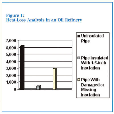
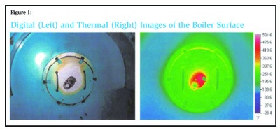
Recently, a heat-loss analysis was completed on the “typical” insulated piping systems within an oil refinery. The analysis illustrated the difference between the worst-case scenario (uninsulated piping), what could be obtained if all piping were insulated, and the case of reality where 21 percent of the pipe insulation was damaged or missing (see Figure 1). Since this analysis was completed, it has been compared to other industry segments—both for hot and cold applications—and determined to be a representative illustration. With 21 percent of the pipe insulation missing or damaged, only 52 percent of the potential heat-loss savings in British thermal units per hour (Btus/hr) was obtained. This is a big number, even if you discount it by 50 percent. Why does this condition exist when it can be corrected to provide a significant return on the capital employed for maintenance?
The typical oil refinery example showed 400,000 lineal feet of piping missing or with damaged insulation, which in turn equated to 5,800 barrels of oil lost per day. At $55 per barrel, that is $319,000 lost per day. These are huge numbers in any industry!
Other examples can be seen in the findings of the Save Energy Now (SEN) program, part of the Department of Energy’s (DOE’s) Industrial Technologies Program (ITP). SEN is part of a national campaign by the DOE to help manufacturing facilities reduce energy and operating costs, and operate more efficiently and profitably. Independent specialists trained to use sophisticated software assessment tools and who have passed a rigorous qualifying exam visit plants and identify immediate and long-term opportunities for improving energy efficiency and bottom-line results. Mechanical insulation is one of the many opportunities examined. (To learn more about the SEN program and see the outcome of one such energy assessment, please visit www.insulation.org/articles/article.cfm?id=IO070703.)
Here are a few mechanical insulation statistics derived from the SEN energy assessments:
- 51 percent of the reports specifically mentioned insulation.
- 63 percent of the insulation opportunities referred to “missing, damaged, or uninsulated areas,” while 37 percent referred to insulation upgrade or improvement opportunities.
Of the insulation references in the reports:
- 81.5 percent were classified as near-term opportunities.
- 14.8 percent were classified as medium-term opportunities.
- 3.7 percent were classified as long-term opportunities.
Savings from insulation were, in many cases, identified in dollar terms—some approaching $1 million per year. Other ROI opportunities could be realized in fewer than 4 months.
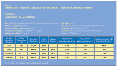
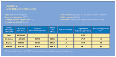
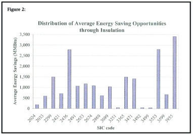
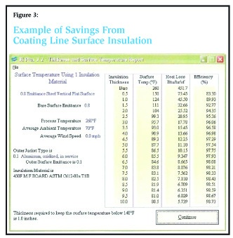
The specific mechanical insulation tool that was used by the SEN program assessment specialists was the 3E Plus® Insulation Thickness Computer Program from the North American Insulation Manufacturers Association (NAIMA). Figures 2 and 3 provide two examples of information obtained using the program.
Energy conservation, with the use of properly designed, installed, and maintained mechanical insulation in the citrus industry—for a hot or cold application—is an opportunity that should not be overlooked. It is an investment that may have few rivals from a return perspective.
Figure 4 provides a graphic overview of the cost of energy compared to the cost of insulation and to the total cost.
Process Control
For process control, mechanical insulation is typically “engineered” into the process. Whether dealing with a fluid, air, or gas, the goal is to leave Point A at one temperature or pressure and arrive at Point B at another, or to be stored at a given temperature. Fluctuating temperatures can cause significant problems in manufacturing quality and productivity, so insulation is a major component of the equipment and manufacturing design process. However, designers do not always understand the various insulation systems available, the mechanics required to determine the correct insulation system, or material properties for specific application. Often, the insulation system or thermal value is determined by what worked in the past. In the industry, this is referred to as “dusting off the old specification.” Unfortunately, the reality is that insulation systems are rarely engineered.
Recently, the wrong old specification was pulled from the shelf and a hot insulation system was specified for a −100°F application. This is a disaster waiting to happen—a perfect opportunity for others to take advantage of the wrong specification in the bidding process.
The knowledge base of mechanical insulation systems at the engineering, architectural, and facility-owner level over the last 15 to 20 years has decreased. This is a by-product of the corporate world’s drive for profits, as well as right-sizing and multitasking objectives. The insulation field is not attracting specialization in the engineering, architectural, or maintenance arenas. This reduced knowledge base has led to the under-utilization or improper use of mechanical insulation in many applications.
With process design, selecting the right insulation system and determining the correct insulation thicknesses and values for the design conditions can be critical to the manufacturing process. This is especially true in the citrus industry, which requires design criteria that will:
- protect against bacteria development;
- address work areas that are subject to continual washdown;
- insulate piping and equipment subject to dual operating purposes;
- prepare for internal and external inspections, such as those performed by the Food and Drug Administration (FDA); and
- provide freeze protection.
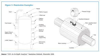
Figure 5 shows one of the design graphics or “plates” from the Midwest Insulation Contractors Association (MICA). This is an integral part of the insulation design guide contained in MICA’s National Commercial & Industrial Standards Manual.
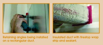
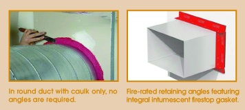
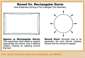
One problem in the citrus industry (and others) is that insulation systems that have been designed, selected, and installed are not being maintained in a timely and proper manner. With improperly maintained insulation, process temperatures and pressures take more energy to maintain. This can affect throughput and costs. A simple but effective example of this is the air-conditioning system in a house or office: If the duct insulation is damaged or missing, the air-conditioning equipment cannot perform as designed.
Process control, quality, and product throughput are major considerations in the citrus industry. Properly designing, installing, and maintaining mechanical insulation systems should be an integral part of both the initial design and operational maintenance management plans.
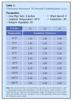
Condensation Control and Mold Prevention
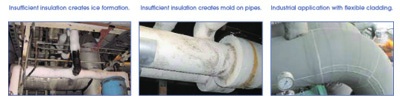
Moisture is an enemy. If an insulation system is not properly designed to maintain the surface temperature above the dew point, condensation will develop. This is a real-world problem that—if not corrected—can lead to other problems. Examples of this include work hazards, due to moisture on the floor, and the development of mold.
Mold is a serious problem in the work environment. Insulation cannot stop mold from developing. However, it certainly helps eliminate moisture due to condensation, which must be present for mold to develop. Prevention is less costly than cure. If the insulation system is not designed, installed, and maintained correctly to prevent condensation under realistic adverse conditions, condensation can occur. This problem should be addressed in an aggressive, timely manner.
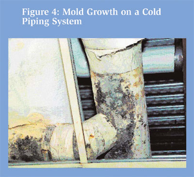
Figure 6 is an example of mold growth on a cold piping system in an uncontrolled utility space.
Moisture Intrusion and Corrosion Under Insulation (CUI)
Moisture intrusion in an insulation system can lead to many problems. By spending some money early on, in a managed approach, one can avoid spending a lot of money later in a reactionary mode.
How does moisture penetrate an insulation system? The primary moisture sources are rainwater, water from a washdown, piping leaks, and water from condensation within the insulation system (especially on dual operating systems). The most likely areas of intrusion are at penetration points, such as gauges or attachments (see Figure 7). If either the integrity or exterior of the insulation system is not installed and maintained correctly, moisture will more than likely penetrate the system. The rate of moisture migration and/or wicking varies depending on the insulation system, the temperature of the operating system, and other conditions.
Moisture intrusion can negatively affect all aspects of the insulation system. Thermal values can have a direct impact on process control, energy cost, condensation control, safety, and the potential of mold development—not to mention the potential for CUI.
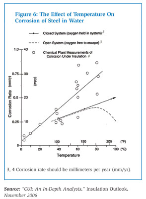
CUI is not new, and in many circles it is well understood; yet it costs industry millions of dollars annually. Unfortunately, the citrus industry is included in those statistics. It is generally accepted that carbon steel operating between 25°F and 300°F is at the greatest risk. Corrosion occurs at those points of water entry into the insulation where the temperature is below 300°F, and the piping and equipment are idle. Stress cracking of stainless steel under insulation is primarily manifested by a combination of water and external sources of chlorides. Carbon and stainless steel corrode because moisture is present. Insulation can provide an annular space or crevice for water retention with full access to oxygen and other corrosive media. Insulation material may wick or absorb moisture, and increase or accelerate the corrosion rate. With the right conditions, CUI is possible under all types of insulation.
If insulation does not directly cause corrosion, could maintaining the integrity of the insulation system minimize CUI and save money in the long term? To answer that question, life-cycle cost analysis should be employed. Without question, removing an insulation system, replacing piping and equipment, and installing a new insulation system is an expensive process. It is possible that an aggressive maintenance program, combined with regular inspections, could be less costly over time.
Reduction of Greenhouse Gas Emissions
Reducing energy consumption by properly using and maintaining mechanical insulation can reduce greenhouse gas emissions currently being released into the atmosphere.
A 1998 study of mechanical and building insulation in commercial buildings, excluding roofing, found that insulation saved 211 billion pounds of carbon dioxide (C02) from being emitted into the atmosphere each year. This benefit is not considered in many applications, but what if it was included in ROI calculations or used in the decision-making processes for a plant? Answers will vary depending on the facility, carbon credits (if applicable), and regulatory requirements. However, the public relations benefit cannot be ignored. Besides, it is the right thing to do.
Personnel Protection
Protecting workers from coming in contact with hot or cold surfaces, and from excessive equipment and other workplace noise, should be a focus of any safety program; yet insulation is seldom, if ever, on the agenda for safety meetings.
The standard is that a surface temperature above 140°F should be insulated for personnel protection, but is this practical and effective? Lowering a company’s experience modification rate (EMR) is a primary objective safety programs. The lower the EMR, the lower the insurance costs. Insulation may not be able to lower the EMR, but it can be an integral part of an accident-prevention program.
The role of mechanical insulation in providing a safe work environment is seldom considered. Far beyond the impact on a company’s bottom line is the direct impact on the well-being of its employees. Can you think of a more important topic or a better reason to think about insulation differently?
Improving the Workplace
Insulation is a major component in improving facility occupant comfort and thus increasing productivity. Many studies confirm that occupant productivity increases when indoor air quality, temperature, and sound are managed within an acceptable range on a consistent basis. Insulation’s thermal and noise-absorption properties thus can provide a real ROI in the workplace.
Sustainable Design Technology
Sustainable design is used more every year. Mechanical insulation’s role is normally included in discussions related to heating, air conditioning, or other equipment. In some cases, the size of the equipment required has been reduced due to the use of increased insulation values. Capital investment is reduced, and the return is increased. That is a winning combination.
Many companies are pursuing sustainable design certification for buildings and plants. This is an effective way to measure success in sustainability. However, thinking green and employing that philosophy are just as important, if not more so, than attaining certification. Thinking, promoting, and selling green can be an advantage within an organization, with customers, and certainly within the larger community.
Insulation: A Powerful Technology
The most obvious benefits of insulation are energy conservation and process control. While those are at the top of the list, there are other important advantages to properly using and maintaining insulation. The combined results make insulation a powerful technology. The need and value of a properly designed, installed, and maintained insulation system is more important today than it ever has been. There are educational programs, software tools, and human resources available that can help explore the many benefits that mechanical insulation can provide. Increased knowledge of mechanical insulation can provide, in many cases, an unrivaled ROI opportunity in the new construction and maintenance arenas. It also can help to reduce our dependency on foreign energy sources, protect our environment, and improve our economy.
The citrus industry is a major user of mechanical insulation, yet it is also a prime example of an industry that has not used mechanical insulation to its full potential. By thinking differently about mechanical insulation and the value it can provide, insulation end users in various industries can take advantage of the power of insulation.
REFERENCES
American Society of Heating, Refrigerating and Air-Conditioning Engineers, Inc.—2005 ASHRAE Handbook, Fundamentals I-P Edition, Chapter 26, Insulation for Mechanical Systems • Midwest Insulation Contractors Association—National Commercial & Industrial Insulation Standards, 1999 Fifth Edition • North American Insulation Manufacturers Association—3E Plus® Insulation Thickness Computer Program, Pub. C12128/05 and Software Program • National Insulation Association—Insulation Outlook, November 2006, “CUI: An In-Depth Analysis” • National Insulation Association—National Insulation Training Program (NITP) • National Insulation Association—“The Power of Insulation” and “Insulation: The Lost or Forgotten Technology” presentations • The U.S. Department of Energy (DOE)—Industrial Technologies Program (ITP), Save Energy Now (SEN), Partner Results
 Figure 1
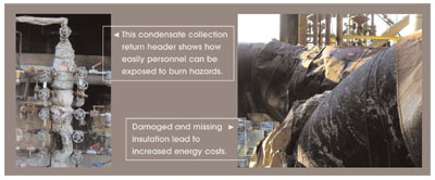 Figure 2