Category Archives: Global

We all know what a furnace is and what it does. It takes an energy source in the form of a combustible fuel, or electricity, and converts it into usable heat inside an insulated outer casing. The economics of this process are simple. An efficient insulation allows the fuel source to be used more efficiently, which lowers the costs of operating the process. Selecting the appropriate insulation also makes fine temperature control much easier and helps the furnace manufacturer to achieve the lightest, most compact design. Careful selection of insulation can mean tremendous cost savings.

Microporous insulation achieves its low thermal conductivity by resisting all forms of heat transfer. Heat transfer through materials takes place by a number of different mechanisms or modes; an efficient and effective insulator must address each of these modes in order to achieve the lowest possible thermal conductivity. The most important modes of heat transfer in insulation materials are gaseous conduction, solid conduction and radiation.

Insulations usually contain significant volumes of air in voids. The air in the voids conducts heat by collisions between molecules, allowing transfer of energy from fast-moving "hot" molecules to slow-moving "cold" molecules.

In microporous insulation, the void volume is 90 percent of the total volume of the material, but because the voids are so small, the collisions between gas molecules are eliminated. Effectively, each air molecule is trapped in a box unable to interact with its neighbors. Air under these conditions has a far lower thermal conductivity than free air. This is known as the microporous effect, and is the primary reason why a microporous material has a thermal conductivity lower than that of still air.

Solid conduction of heat is more significant than gaseous conduction, and occurs when atoms in a material are heated and increase their vibrational energy. Interactions with their neighbors pass the energy along chemical bonds from atom to atom through the structure leading to a transfer of energy away from the heat source.

Microporous insulation minimizes solid conduction in several ways. The most important is the low density of the material, with a high ratio of gas to solid. Furthermore, microprous insulation is largely composed of amorphous particles with a low intrinsic thermal conductivity compared to most solids. Finally, the particles are very small and randomly packed, which results in long heat paths through the material along which solid conduction can take place. Heat flux by conduction is inversely proportional to the distance along which the heat has to travel; so long heat paths reduce heat transfer.

As temperatures increase into the hundreds of degrees, the above modes of heat transfer become less important and most heat transfer takes place by direct infrared radiation. It is essential that high-temperature insulation is dimensionally stable and not subject to shrinkage or any other movement at very high operating temperatures.

Microporous insulation is formulated using controlled materials to withstand high temperatures without damage. It can also be used as a backup insulation behind other refractory materials.

The characteristics of mircroporous insulation make it a good choice in furnace design for a wide diversity of applications, from small laboratory furnaces to the very large process furnaces used in manufacturing.

An example of a large-process furnace application is a roller hearth reheat and treatment furnace built by Wellman Furnaces (United Kingdom) for use in an automotive application in the United States. The furnace is 85 feet long and gas-fired.

Inside the furnace, the expensive rollers, which are able to withstand the high operating temperature, are an important design cost consideration. The use of microporous insulation ensured the minimum wall thickness for optimum efficiency. This in turn allowed shorter, less expensive rollers to be used.

Another common application for microporous products is in glass furnaces for bottle manufacture. Because of the constant need to minimize temperature gradients in the molten glass, tailored kits of insulation components are supplied for forehearths, feeder bowls, feeder bowl covers, orifice rings as well as for the general insulation of walls and recuperators for optimized efficiency.

The quality of fit is critical, particularly at corners and penetrations where gaps in the insulation can result in serious heat leakage paths, which reduce operating efficiency and create hot spots on the outer casing.

Good design should not be about using the cheapest components and materials. The most cost-effective solutions include a well-engineered design, quality components and a microporous insulation that provides optimal performance for the specific application.

For its firestopping issue, Insulation Outlook asked Jerry Heid of Zero International, a manufacturer of intumescent materials, to speak with those on the front lines of firestopping – an engineer at Underwriters Laboratories, a fire marshal and the president of a firestop consulting firm – and pinpoint the issues most important to firestop installers.

Today’s building and life safety codes recognize the vital role of passive fire protection systems for preventing the spread of fire, smoke and poisonous gases, buying time for safe evacuation of occupants and helping protect firefighters. The codes are clear that fire-rated walls and floors, when breached, must be firestopped to restore their original design integrity. While the building industry debates proposals mandating the use of certified specialty contractors for this critical life-safety application, the reality remains that insulation contractors often find themselves on the front line of firestopping. Regardless of who drilled the hole, insulators working across the trades in practice can end up owning the breach and responsibility for closing the opening.

Properly installing tested firestop systems to maintain fire ratings demands understanding and precision. With life safety at risk and plenty of liability to go around for performance failures in a fire, application mistakes can incur costs far beyond what it takes to remedy failed inspections. When it comes to firestopping installations, being forearmed with knowledge beats dodging bullets every time.

Using approved specialty firestop contractors is without question a prudent course for construction managers and owners. The Firestop Contractors International Association (FCIA) offers contractor education and certification through Factory Mutual (FM) Research acting as its qualified testing agency. And FCIA continues to advocate for incorporating its FM 4991 installer certification standard into master specifications.

For insulators faced with responsibility for firestopping on the job – and for those considering certification – this article highlights some of the major code and enforcement issues that can have an impact on planning and firestop application. For that purpose, we have assembled a team of industry professionals who offer insights reflecting their various expertise in manufacturing, testing, enforcement, inspection and consulting to firestop standards in both the International Building Code (IBC) and National Fire Protection Association (NFPA) 5000 model building codes. Municipalities across the nation are in the process of adopting one or the other of these two codes. Both codes preserve firestop requirements already established and enforced under all current major codes.

Meet the Experts

Richard N. Walke is staff engineer for the Fire Protection Division of Underwriters Laboratories. As head of the architectural services group, which provides services and information to users of the UL directory, Walke often speaks to industry groups and presents educational seminars on fire protection issues. Prior to his current assignment, Walke was involved for 17 years in the testing of hourly fire-resistive assemblies, including firestop systems.

Karl K. Reynolds is fire marshal for the North Naples, Fla., Fire Control and Rescue District. Throughout his 19 years on the job, Reynolds has espoused a highly proactive approach to both firestopping inspection and education. He sees ongoing education as the key to solving the three biggest problems he observes in firestop applications: 1) lack of formal training; 2) installer difficulties in reading tested assemblies in the directories; and 3) not following the specifications. The Florida Building Code, which is currently based on the Standard Building Code (SBC), will adopt IBC as its base in early 2005.

John Sinisi is president of Firestop Inspector LLC in Manasquan, N.J. Sinisi’s firm provides a full complement of consulting services intended to optimize firestop planning, application and inspection. These services include: plan review and site surveys to identify fire barrier breaches; forensic investigation for the same purpose for renovations; barrier documentation and labeling; inspection and verification to ASTM standards; training and education; and expert testimony. Sinisi also offers third-party inspection services.

Here are some issues these experts have found to be especially important to firestop installers – and their advice to insulation contractors who have to manage them in their installations.

Provide Tested Assemblies and Documentation

The fundamental requirement for firestopping established by IBC 2003 Sections 712.3.1.2 and 712.4.1.2 is using tested and approved assemblies and methods. All requirements for maintaining assembly ratings are detailed in directories published by UL and other testing agencies. Walke notes that listings in the UL fire-resistive directory include basic layouts with detailed explanations of configurations, conditions, and installation parameters and procedures. The hourly ratings included in each system apply only to the complete system, constructed and installed as specified in the system. The individual components are not interchangeable between systems.

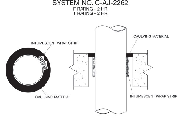
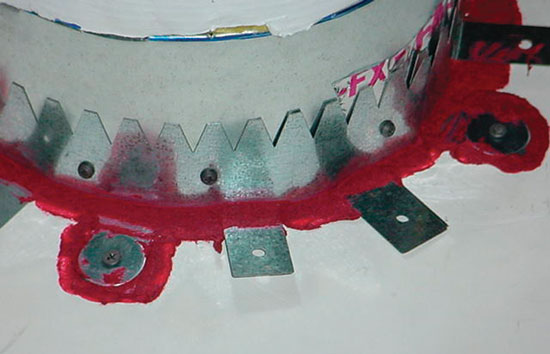
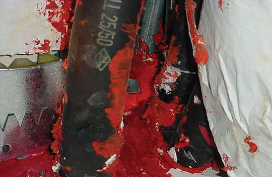
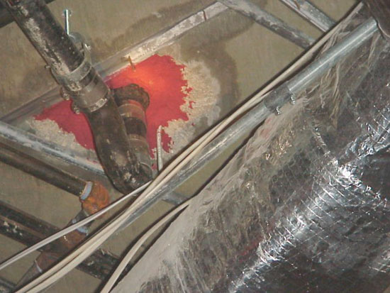
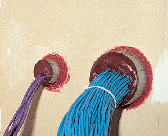
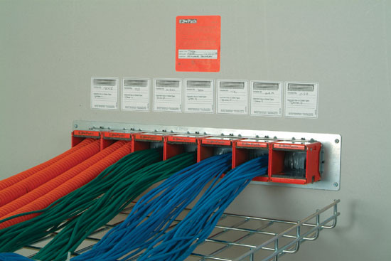
What this means to firestop installers in practical terms, using familiar examples provided by Reynolds, is that caulking at the intersection of a ¾-inch pipe in a ¾-inch hole is not acceptable. If the caulk is not inside the membrane, it will expand outward in a fire and fall off. On the other hand, approved systems covering plastic pipe greater than 2 inches in diameter typically include intumescent wrap strips applied in a specific manner, with a metal collar to direct expansion inward as the pipe softens, attached with approved anchors to the bottom of the slab and using hose clamps or screws to close off the collar. Or an approved tuck-in system might be used with wrap strip placed around the pipe, held in place with wire or aluminum tape, and then pushed into the opening.

Intumescent caulking in a prescribed manner to a specific depth might be approved for certain applications. In all cases, the hole must be drilled larger than the pipe, and the allowable size of the annular space varies by tested system. Reynolds also points out that industry strides in minimizing required product volume make the need for precision in firestop installations even more urgent.

Manufacturer specifications may not cover all necessary installation details, so Reynolds requires contractors in his district to take copies of tested assemblies from the directories and provide them to authorities having jurisdiction (AHJs). The documentation serves as reference for both installers and firestop inspectors. He advises contractor superintendents to keep assemblies on file with copies in each service truck and at each job site. Reynolds devised a notebook specification system that has been in place in North Naples, Fla., for more than five years. "Installers usually end up using the same three to five assemblies for each kind of penetration – concrete, drywall and wood frame," he said, "Keeping those assemblies permanently on file probably covers 90 percent of what you will find in the field."

Reynolds emphasizes the vital role of education for understanding specifications and properly installing firestop assemblies. He explains, "Firestopping can only be enforced to the level of the AHJ’s knowledge of the codes and specifications for the tested assemblies. To ensure that everyone is on the same page, we start by educating the AHJ in both the fire service and building departments. Here in Collier County, the Fire Marshals Association has been providing seminars for both the AHJs and contractors to learn about the proper installation of firestopping together at the same time. This way everyone hears the same thing, and it helps to bring the industry together."

For any contractor installing firestopping, knowing what the AHJs expect is essential. If your fire district does not provide a similar education program, it makes good business sense to ask for it. The International Firestop Council (IFC) also provides training for this purpose. In addition, ask for pre-construction meetings with the AHJs.

Identify and Plan for Needed Engineering Judgments

Sinisi notes, "In new construction it is important to extract a schedule of issues to be ‘repaired’ from the design prints. This list provides the basis for inspection and statistical analysis throughout the project. Also recognize that ‘unplanned’ openings of fire-rated walls and floors on the construction site are common. If the print calls for a 2-inch hole to be drilled, and the carpenter has a 4-inch bit on his drill, you may have a modification made in the field that requires a change in repair system selection."

Change orders require reviewing submittal documentation and going back to the original design drawings to determine what barriers have to be breached and repaired. Sinisi cautions firestop installers to be alert to the consequences of improvised solutions, such as pipe installed through someone else’s opening in a rated wall, and advises dating all work to safeguard against your work being compromised. (His firm labels openings with bar codes to identify ownership and dates.)

Virtually every job will include some unusual penetrations or requirements for which tested assemblies do not exist. In addition to unplanned openings and change orders, perhaps someone simply changes a pipe. Or a renovation reveals an odd configuration of pipes. If there is no specific test for that specific situation, you will need an engineering judgment acceptable to the AHJ.

The best time for identifying the need for judgments is during the development of plans. Walke observes, "Ideally, architects should identify and resolve all firestop issues, including necessary judgments, as part of the submittal package to the municipality. More often it’s caught during inspection – leading to delays."

As best practice, contractors should ask during plan review if any engineering judgments would be needed. Factor that information into your bid price and scheduling.

When you do encounter an unusual or altered requirement, Walke advises first looking for a different system on the manufacturer’s website (most have web-based selection guides) or in the directory – or select a published system from a different manufacturer. He estimates there are rated systems for probably 95 percent of single-pipe penetrations. If nothing in the directories fits the field parameters, the next steps are:

  • Ask the manufacturer for an engineering judgment, which is often acceptable to AHJs.

  • If the AHJ will not accept the manufacturer’s judgment, the manufacturer, contractor or architect should then request one from the testing agency. The agency often uses the manufacturer’s submittal as a starting point and documents the judgment in a letter outlining any exceptions and attaching a drawing.

Keep in mind that engineering judgments are issued for specific penetrations on specific jobs only and are not transferable. The IFC publishes guidelines for engineering judgments, which are recommended for installers’ reference.

Be Aware of Gray Zones

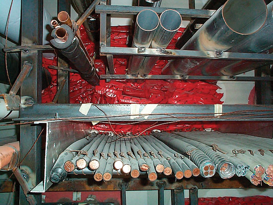
Walke identifies other issues that may constitute obligations for firestop installers even when solutions or code requirements are less than clear. To the first point, he advises that IBC and NFPA 5000 both require T ratings equal to floor ratings for all firestops through floors. This is difficult to achieve for metallic penetrations because of the thermal conductivity of the penetrants. The 2004 UL directory includes various systems using thermal insulation, such as fiberglass or mineral wool, to achieve these ratings. However, these systems will not work for copper pipe conduit for cabling, which generates heat that cannot dissipate normally when insulated, potentially leading to hazardous overheating.

The National Electrical Code, NFPA 70, addresses the need for "ampacity derating" in conduit using tests for determining what reduction in current load is needed to maintain temperature within acceptable limits. However, manufacturers have not done much testing to this standard. Although some AHJs are overlooking this issue, until tested solutions become available Walke encourages firestop installers to plan ahead and protect themselves by raising the issue for discussion with AHJs.

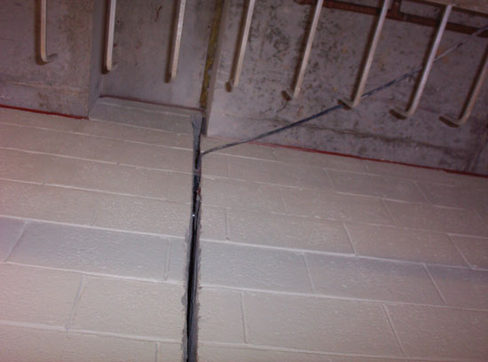
A similar dilemma for contractors comes out of IBC (Section 710.6) and NFPA 5000 [8.10.4.2] requirements for preventing the passage of smoke when non-fire-rated smoke partitions are penetrated. "No published UL systems currently exist," says Walke, "so contractors end up on the line making judgments about what is needed and how to resolve it. Your options here are to install a fire-rated system in the non-rated wall – and that will probably be acceptable to AHJs. Or push for manufacturers to start testing systems for that purpose."

In other areas, contractors can have implied and legally enforceable obligations that exceed explicit code requirements. Walke observes, "Smoke migration through a building during a fire is responsible for many deaths. UL developed an L leakage rating for firestops approximately 12 years ago." The L rating, which provides quantifiable measures of performance, remains optional. Although industry efforts to add the rating to the building codes have met resistance due to cost concerns, the codes still contain generic language requiring contractors to install systems with low smoke leakage.

Walke reminds us that the legal standard of responsibility is always to the highest available level of life safety, regardless of code requirements or omissions. There are rated systems available offering low smoke leakage, and he advises contractors to select those systems to meet the higher standards of performance.

Be Prepared for Inspections

Reynolds tells contractors to check their work using the same methods the firestop inspector will use. In Collier County, Fla., he requires inspectors to use flashlights for good visibility in unlit interiors, and they use ladders and mirrors as needed to be able to see the top of each penetration to confirm adequate caulking to meet the specs.

Using standard sampling procedures and engineering practices defined by code, Reynolds’ inspectors conduct selective destructive testing to confirm compliance with firestop requirements. He explains that it is necessary to probe with a knife "to confirm that caulk and wrap strips have been put into the annular space, they have minimum space, and they have not exceeded the annular space around the penetration." Inspectors also tap on backfilled, abandoned holes using hammers or knives to listen for telltale signs of improper backfill materials, such as newspaper or batten insulation, used in place of the required nonshrink grout. He prefers to see installers use tested assemblies for abandoned holes.

When inspectors find a bad installation on the first sample, you can expect a lot more destructive testing, and often it is necessary to redo all. Reynolds asks contractors to be present during inspection and patch "as they go."

Also commenting on inspection methodologies, Sinisi explains, "Verification of all installed systems to a specified tested system drawing is the best method to assure compliance, but is impractical for most jobs. Although it is impossible to inspect every penetration and joint system on a project, random sampling techniques supported by industrial engineering principles and documentation can help guide the inspection. ASTM E2174 (Inspection of Installed Firestops) provides standard statistical techniques for assuring installed system confidence. All require a schedule of systems to be inspected and inspection zone square footage to be predetermined. This is possible on new and existing buildings by employing a standardized method of documenting openings in your rated walls and floors."

Third-party inspectors such as Sinisi’s firm are available to assist municipalities lacking the expertise or time to follow the example of Reynolds’ district in inspecting firestops to those standards. Walke points out that firestop contractors and the FCIA are promoting code provisions for third-party inspection, similar to requirements already in the codes for inspections of fireproofing for structural steel.

Sinisi notes that contractors can themselves benefit by employing third-party inspectors for independent verification of installed systems. "Where AHJs inspect to code," he said, "third-party advice can help installers demonstrate adherence to best-available standards and methodologies."

Avoid Raising Red Flags

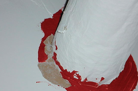
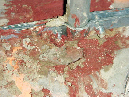
Reynolds offers several examples of common installation mistakes that cause firestop inspection failures – and accrue high risk of performance failures during fires. "Fire caulk spread two to three inches around the penetration is a red flag to inspectors," he said. "That usually means the annular space exceeds the specified maximum. Using a hammer to make the opening blows out the inside of the drywall, which makes it impossible to meet tested specifications for either caulk-only systems or intumescent wrap strips. Making the hole with the appropriate-size drill bit will make all of our jobs easier."

Reynolds cautions against mixing different caulks in the same hole, using different types of caulk on each side of a penetration, and cutting wrap strips lengthwise to "economize." None of these uses conforms to specs for tested assemblies; manufacturers will not back them; and inspectors will reject them.

Walke advises close attention to the proper placement of wrap strips in tuck-in applications in floors. If installed at the top of a thick floor slab, the intumescent material will be shielded from heat during a fire, potentially delaying or preventing its activation. "Be careful to install as specified," he said, "and understand that there are consequences if you don’t follow the details."

Curtain walls are especially difficult to protect, so Reynolds advises following specifications precisely. Pin tabs holding installed fiberboard must be placed at specific intervals. Inspectors will also look for required compression in the fiberboard inserted at the slab to fill the rest of the opening. AHJs will inspect these installations at each of three stages: 1) cross bracing and pin; 2) fiberboard installed with compression; and 3) application of spray-on or elastomeric product.

In the end, it all comes down to following those details. As Sinisi concludes, "Know and understand the firestop requirements before you start. The size of the opening is part of the system; so be prepared to drill a hole to the specified width. Know the specified systems and how to install them. Go in with a plan and stick to it."

The passive fire protection industry has provided many practical tools and guidelines to help installers firestop cost-effectively, ensure installation quality and limit their liability. With so much at stake, however, all our experts agree the safest, wisest course is using certified contractors for firestopping. For insulation contractors on the front lines, their best advice is: Consider getting certified yourself – or designate someone on your team to specialize and become an expert in the complexities of firestop requirements and installation.

Figure 1

Firestop Systems C-AJ-2347 (Figure 2) and C-AJ-2262 (Figure 1) published in the UL directory are typical tuck-in systems with wrap strip installed around the pipe and caulking material applied at the slab. Installed from the bottom of the slab, systems such as C-AJ-2347 offer better fire performance than System C-AJ-2262 and other systems installed from the top, where the top of the assembly may delay or prevent the activation of the intumescence.
Drawings courtesy of Underwriters Laboratories.

Figure 2

Firestop Systems C-AJ-2347 (Figure 2) and C-AJ-2262 (Figure 1) published in the UL directory are typical tuck-in systems with wrap strip installed around the pipe and caulking material applied at the slab. Installed from the bottom of the slab, systems such as C-AJ-2347 offer better fire performance than System C-AJ-2262 and other systems installed from the top, where the top of the assembly may delay or prevent the activation of the intumescence.
Drawings courtesy of Underwriters Laboratories.

Figure 3

Using drywall screws to anchor the metal collar of this firestop system is not acceptable to AHJs.
Photo courtesy of Karl Reynolds.

Figure 4

Caulk widely spread out from the base of this insulation raised a red flag for inspectors. Drywall skin peeled away during destructive testing, which revealed annular space that is too small for the firestop insulation. The hole has to be drilled larger than the penetrant up to the allowable maximum for the annular space.
Photo courtesy of Karl Reynolds.

Figure 5

There is no way to repair an opening with multiple penetrants. In this example, the installer attempted to do so using a large amount of caulk, which caught the attention of the inspector.
Photo courtesy of Karl Reynolds.

Figure 6

A mixed multiple penetration, as shown, requires an engineering judgment for firestopping acceptable to AHJs.
Photo courtesy of Firestop Inspector LLC.

Figure 7

The 2-inch pipe shown at right replaced a 1/2-inch pipe as a result of a change of order. However, the installer failed to replace the original firestopping. The firestop system for the pipe at left is correctly installed.
Photo courtesy of Firestop Inspector LLC.

Figure 8

Improper installation caused this assembly to ignite non-fire side leading. The plastic pipe was consumed by flames, essentially leaving an open hole in its place.
Photo courtesy of Underwriters Laboratories.

Figure 9

Inspectors use hammers or knives to tap on backfilled holes to listen for telltale signs of improper materials, such as trash stuffed in the hole before topping off with nonshrink grout. Tested assemblies should be used for abandoned holes.
Photo courtesy of Karl Reynolds.

Figure 10

The perils of working without a plan for repairing breaches are evident in this view of annular space in floor penetrations filled in with roofing tar.
Photo courtesy of Firestop Inspector LLC.

Figure 11

This installation mixes foam and two different caulks in the same hole, which does not conform to specs for tested assemblies.
Photo courtesy of Karl Reynolds.

Figure 12

As a result of a specification error, a contractor firestopped only the horizontal gaps in this fire-rated wall, leaving all vertical gaps exposed.
Photo courtesy of Firestop Inspector LLC.

Figure 13

In this example, the excessive spread of red caulk alerted inspectors to a hole size that exceeded the allowable maximum for the annular space.
Photo courtesy of Karl Reynolds.

Having worked in technical services for a firestopping manufacturer for many years, I have heard just about everything regarding firestopping products and practices. It is amazing how certain fallacies or inaccuracies can develop and spread like wildfire throughout the industry. Let’s dispel some of the myths surrounding firestopping.

Firestopping caulks and sealants must be red in color.

This is a common misconception. There are no code requirements that specify that a firestop sealant or caulk must be red. In fact, firestopping sealants and caulks come in a variety of colors to differentiate the type of product and its use. For example, many leading firestopping manufacturers color their intumescent sealants red and use other colors for nonintumescents while others make no distinction. Intumescent sealants expand with heat to close off combustible penetrants. Nonintumescent sealants are designed for metallic pipes (noncombustible penetrants) and are nonexpanding. To avoid misapplications, carefully read the label and UL test.

Polyurethane foam is an adequate firestop.

Don’t assume that any product is a firestop product unless it bears the correct markings from a third-party testing or listing agency. Even then you must be careful that the affixed third-party listing applies to fire resistance. For example, insulation foams in aerosol cans typically bear a label that indicates flame spread and smoke development ratings. This type of listing also applies to paints, wallpapers and certain furnishings. Low-density polymer foams typically ignite very readily and are quickly consumed by fire. This makes them a poor choice as a fire-barrier material unless they have been specifically formulated and appropriately tested for this type of use.

All pipe insulations are firestopped the same way.

Not true! The fire performance of pipe insulations can vary dramatically. Some noncombustible insulation such as mineral wool actually resists fire and aids in the firestopping process. However, low-density polymer foam insulation, for the same reasons noted above, can be much more challenging to firestop. For this reason, UL Classified systems are material-specific to insulation type, thickness, density and firestopping material. Before selecting an insulation material, make sure suitable firestop systems are available.

Sleeves are always required for cabling passing through fire-rated barriers.

While sleeves are often used to create openings for cables passing through fire-rated barriers, there is nothing in the codes to specifically require them. The use of sleeves is totally at the discretion of the specifier or installer. Sleeves are often preferred for cabling penetrations because they act as a container for both the cables and the firestopping material. Sleeves and nonhardening firestop putties are a great choice for datacom cable penetrations subject to frequent moves, adds or changes. Whether you elect to use sleeves or not, appropriate UL Classified systems are available for either installation choice. Be sure to choose a design that is appropriate for your selection. One more thing about sleeves: Make sure that they are attached to the barrier. The codes do require this!

Cable trays are not approved to pass through fire-rated barriers.

This is another fallacy. Again, there is no specific limitation within the codes that would preclude running trays through rated walls so long as they are properly firestopped. And the 2003 UL Fire Resistance Directory Volume II has more than 200 classified through-penetration firestopping systems that are specifically designed for cable trays passing through fire-rated wall assemblies. Using UL’s alphanumeric system for firestop systems, be sure to check the 4000 series numbers for cable tray systems that penetrate the barrier.

Terminating the trays may make firestopping easier in some types of applications. When this happens, be sure to check 3000 series UL Classified systems to find an appropriate design for cables (only) penetrating the barrier.

Wire mesh is required for pillow and cushion-type firestopping systems.

This is not always the case. Several of the more prominent firestopping manufacturers have successfully tested their materials to eliminate the need for wire mesh. It is important to consult the individual tested designs to determine whether or not wire mesh is required. In some cases, wire mesh may be desired as a security method to prohibit unauthorized access to the firestopping system.

Nonshrink grout is an acceptable firestopping system.

There are no tested systems for nonshrink grout installed in the annular space around cables or steel conduits. Nonshrink grout, not properly tested or evaluated, can crack and spall in the presence of high heat and flames, causing the firestopping system to dislodge.

Drywall mud and tape is an approved firestop for cables through gypsum board/stud walls.

Drywall mud is not a tested and approved method of firestopping cables passing through gypsum board/steel or wood stud wall assemblies. Drywall mud is approved for covering seams between adjacent layers of gypsum board in fire-rated assemblies. However, it is not a gap or void filler used for the annular space between cables and the periphery of the opening. Furthermore, the brittle nature of drywall mud can cause it to crack or deteriorate over time due to the weight of the cables resting atop it. Most drywalls mud-type products are water-soluble. Thus, moisture can cause such products to dissolve and deteriorate.

All listed or classified through-penetration firestop systems have been evaluated for smoke leakage.

This is another misconception that is rampant within the firestopping industry. The fact that a firestopping system has been tested to applicable firestopping standards does not mean that it has been evaluated in terms of its ability to impede the passage of cold smoke from compartment to compartment. The fire test standard, Fire Tests of Through Penetration Firestops ANSI/UL 1479, includes an optional air leakage test, which a manufacturer can choose to run on its products to determine the amount of air leakage (in cubic feet per minute per square foot) through the firestopping systems. Such systems include an L rating in addition to the standard F and T ratings shown. If a system does not include an L rating, it has not been evaluated with regard to its ability to block smoke, and installing contractors should proceed with caution as they might not meet the intent of the building code.

ASTM E136 is a test method used to evaluate through-penetration firestopping systems.

ASTM E136 is never used to evaluate through-penetration firestopping systems. In fact, it is generally used as a reference for sealants formulated from inorganic materials such as stone or mineral powders used for purposes of fireblocking or draftstopping in nonrated, residential single-family homes. Whenever contractors or specifiers see a reference made to ASTM E136, they should proceed with caution and verify that ASTM E814 is also shown on the tube or pail. If ASTM E814 is not listed as a test standard, the product is only approved for nonrated, residential construction.

Nonintumescent sealants may be used for insulated pipes and combustible polymer-jacketed cables.

Sadly, in some instances this is true. Certain manufacturers have tested nonintumescent (nonexpanding) firestopping sealants for insulated pipes and combustible polymer-jacketed cables. Such systems are heavily dependent upon a number of factors, including thickness of pipe insulation, or the type and size of cable and the amount of cable passing through the opening. In addition, some systems may require the use of noncombustible damming materials or thicker seals. As a general rule, intumescent sealants should be used for materials that will burn away. Intumescent sealants that expand with heat are capable of forming an insulating char that squeezes down tightly on polymer-jacketed cables, minimizing the potential for the cable jacketing to ignite and propagate the fire from compartment to compartment. If the installing contractor is using a nonintumescent sealant, caveat emptor – let the buyer beware! Verify that the sealant is tested and approved for the types and sizes of cables being installed.

Firestopping products are rated for a specific hourly duration (e.g., one-hour, two-hour, etc.).

Contrary to popular belief, firestopping products are not rated by themselves. Firestopping products are installed in a particular manner to attain a specific hourly rating, but that rating is dependent upon the performance of the fire-rated barrier as well as the penetrating item (e.g., cable, pipe, conduit, etc.). Firestopping products are installed as systems. Only a system carries a rating, not an individual product.

Summary

One way to separate facts from myths is to become more informed on firestopping. A great source of information is Underwriters Laboratories’ annual Fire Resistance Directory, Volume II, or its online certifications directory at www.ul.com/database. Both the book and the website contain up-to-date information on tested and classified systems for through-penetration firestopping. In addition, most of the more credible firestopping manufacturers offer training classes on firestopping products and systems. Contact a firestopping manufacturer to arrange for a consultation and training class for your installers. Remember, firestopping is more than simply installing sealant in a hole. Firestopping is a critical component of a building’s overall life-safety system. A properly installed firestopping system protects property, but more importantly, saves lives by inhibiting the spread of fire from compartment to compartment and buying valuable time for occupants to exit the structure in the event of a catastrophic fire.

Figure 1

Sleeves and non-hardening firestop putties are a great choice for datacom cable penetrations subject to frequent moves, adds or changes. Codes require that the sleeves be attached to the barriers.

Figure 2

Firestopping cable pathway devices can be ganged together to increase cable loading and/or help organize cabling types going through the same area in a wall. These cable pathways present a neat appearance as well as organize the multiple electrical and datacom cabling required for today’s buildings.

Figure 3

Re-enterable products such as firestop pillows conform easily to the contours of the piping system.

Mistake Number Four: Thinking that managing safety doesn’t require leadership.

"You manage inventory – you lead people." – H. Ross Perot

This may come as a shocking revelation to the organizations we led, but few managers grew up with the idea in mind that someday, we’d be get to be the leader. That’s not how it happened.

When we were kids growing up in school, we all knew who the leaders were. They were the ones who were the best athletes, had the best personalities, and yes, were the best looking. Everybody–us included–followed them. They made leading look easy–and cool.

We made up for our lack of natural leadership talent by studying hard and getting good grades. Ultimately, that led to graduation, and the beginning of a good career. Then one day, someone noticed what good jobs we were doing, and decided to make us the leaders: We got our first jobs in management.

Then it was our turn to be the leaders. We quickly found out that nobody thought we were all that cool, and employees didn’t necessarily follow our lead. That’s when we decided that the game was all about "managing," and we really didn’t need to lead.

Managing, Defined

Consultant Louis Allen defined the four elements of management as planning, leading, organizing and controlling. They are all critically important to the goal of sending people home safe at the end of the day. Planning is about having systems that put the right tools, equipment and methods in the hands of those who are doing the work. The work of organizing makes certain that the right people are doing the work, and that they have the knowledge, skill, support and supervision they need. Controlling, as Allen defined it, is the work of measuring and following up.

Then there is leading. It’s such a simple concept. Break leading down into the component elements–actions such as communicating, decision-making, listening, motivating–it doesn’t seem all that difficult.

But, that’s not how it worked when we did it. We’d announce an important decision to our staff–communicating it by explaining all the reasons why it made perfect sense–and it would be met with stiff resistance. We’d remind people what we had said before, and they say that it’s the first time they ever heard it. We’d listen patiently, but what we’d usually wind up hearing were gripes and excuses.

Our Most Admired Leaders

Think about the question, "Who are the leaders we have known in our lifetime and admired the most?" We sort through the ranks of coaches, generals, elected officials and public figures; it isn’t hard to come up with a list. Thanks to television and the movies, the odds are high that the names on the list of us baby boomers are pretty similar.

It’s striking what our most admired leaders don’t have in common. Some were brilliant speakers, and others complete introverts. Some led with formal authority, and others just seemed to be able to "create followers" for their ideas. Some were steely-eyed tough guys–like General Patton, and others led in a very passive way–like Gandhi.

What our most admired leaders have in common is a very short list. They all had something important they wanted to accomplish; they acted on their convictions, and their actions produced results. But how they accomplished what they did seems dependent on their personal strengths and personalities. For instance, Vince Lombardi and Tom Landry both enjoyed success on the field, following two entirely different coaching styles.

The leaders we admire didn’t have it easy. At some point along the way, most suffered because of what they believed. At the worst, they were shot or put in prison. Or, they might just have been roasted by public opinion and threatened with being fired.

All that helps explain why real leadership is so rare. And why it’s much more comfortable and safe to just manage–plan, organize and control.

When it comes to safety performance, there is always plenty to manage. Perform the inspections; maintain the equipment; provide the training; complete the assessments. As managers, we all knew the drill perfectly well; most of us were really good at these management activities.

The problem with that, as Ross Perot summed up so well, is that "You manage inventory; you lead people."

Managing Safety Performance Demands Leadership

There are always fingerprints to be found on the reasons why people get hurt. Safety ultimately boils down to a people game. With people, there is no getting around the need to lead, and, with that, brings along all the challenges that come with being the leader.

Being the leader is a really tough duty. Thinking we could get great safety results just by managing–but without leading–is one of the biggest mistakes we managers make.

Mistake Number Three: Trying to manage attitudes.

"The actions of men are the best interpreters of their thoughts." – John Locke

It’s a scene that everyone in operations and those of us who have ever managed operations know all too well.

We’ve gathered up the entire department for an important safety meeting–important because we’re rolling out a new company safety policy. Everyone in the outfit is sitting in the meeting room as we walk in to lead the communication session.

There in the front row, where most of the seats are empty, are three of our very best folks. Smiling, happy to be in the meeting, and interested in what is about to be announced, they even look glad to see us. We’re more than happy to see them. In fact, we wish the entire room were full of people just like them.

But life in operations isn’t like that. Occupying the middle rows are more than a few who sit and wait to size up what they’ll hear.

Then there’s the back row.

Every chair filled. You’d think the meeting was a standing-room-only crowd–iif it weren’t for all the empty seats right in the front row. Spanning the back of the room, arms folded, hats pulled down, and sunglasses on, we’d always see "the usual suspects."

We can’t say that we’re the least bit surprised. We wait in anticipation–dread would be closer to the truth–for what they’ll have to say about the policy. The best we could hope for is that they just say nothing. Of course it never works out that way, and once they get involved in the action, it’s never a pleasant experience.

Every organization is made up of people in the front row, the middle rows, and the back row. Billy Martin once said the role of managing a baseball team was to keep the 12 players who were sure you were nuts from convincing the 12 who hadn’t made up their minds.

If only we could change the attitude of those in the back of the room to be something more like those in the front.

Managing Attitudes

Changing attitude seemed like great idea, and, brother, did we ever try. We paid consultants to run attitude surveys. We put up banners proclaiming, "The A in Safety stands for Attitude." We hung posters in the conference room to remind everyone that "Your safety performance starts with your attitude."

When all else failed, during performance evaluations we did our best to counsel and coach those with attitudes still lacking.

For all our effort, what did we have to show? Rarely anything.

Genius at Work

One of the benefits of growing up in management in the baby boomer generation was that we got exposed to some of the greatest thinkers on the subject of management: notables like Peter Drucker, W. Edwards Deming, Tom Peters and Philip Crosby.

Add to that list Dr. Richard Beckhard.

The name Richard Beckhard might not be quite as familiar to our generation. Measure the impact of ideas on the world of people at work, and you’d find Beckhard to be the equal of Deming. Beckhard’s expertise lay in the field of organization behavior: the relationship between people at work. Just as Deming applied the principals of statistics to manufacturing product quality, Beckhard translated the principals of human behavior to the working world.

A longtime professor at MIT, Beckhard served as consultant to some of the biggest companies and industries around. In the 1970s, when the commercial aviation industry concluded that miscommunication in the cockpit was a leading cause of accidents, the industry hired Beckhard to look into the problem, figure out the causes and make recommendations. Beckhard’s work served as the basis for what is today known as CRM–crew resource management.

The Doctor Makes a House Call

Almost 20 years ago, a small group of managers had the rare privilege of spending a day with Beckhard, in what amounted to an open forum.

If we were expecting the towering presence of W. Edwards Deming, or the dapper elegance of Peter Drucker, we were in for a surprise. Beckhard looked–and acted–like he’d be just as comfortable sitting up in a big chair–as Santa Claus at Macy’s. What a wonderfully approachable icon.

Of course, none of us were smart enough to come prepared with good questions; so Beckhard held class. And the impact was lasting.

CRM – The Inside Story

Beckhard told us all about his experience with the aviation cockpit crew study. "How can you see what’s going on without actually being there?" he asked. His solution: Fly in the jump seat and take lots of notes. We still chuckle at the thought of Beckhard trying to buckle in the narrow confines of a cockpit jump seat. Bet that Santa never had to put up with that.

As he watched life in the cockpit unfold, it became clear that a considerable segment of the airline pilot population, growing up in the military, fell into the trap of giving and accepting orders without questioning command decisions. That unquestioning adherence to the orders of the captain had, on more than one occasion, led to fatal errors in judgment.

>Beckhard on Attitude

A student of human behavior, Beckhard didn’t disagree the soundness of our premise that, by managing attitudes, we’d be fixing the root cause of behavior. But, Beckhard went on to point out, trying to manage attitude leaves you with two problems, neither of which are inconsequential.

The first problem: It’s up to the individual to make the change in attitude. You can’t do that if you’re the manager.

The second problem: How do you know for sure what the attitude is in the first place?

Can You Hear Me Now?

Two simple statements, and two profound insights into the challenge of managing people at work. The real geniuses have the ability to explain things in simple terms the rest of us can understand.

Beckhard made his case on the folly of trying to manage attitude to a small group of managers almost 20 years ago. I’m sure we weren’t the only ones to have heard his message on the subject.

If we’d taken it to heart, we would see fewer posters urging people to have the right attitude about safety; we’d see fewer safety attitude surveys; and hear less about working on "culture" to get everyone thinking the same way about safety.

But most of us didn’t hear the message, and we keep plugging away on changing attitude as the way to improve safety performance.

It’s one of the biggest mistakes managers make, managing safety performance.

Removable/reusable insulation for very high-temperature applications calls for special consideration. 500 F is the material manufacturer’s temperature limit for both silicone and polytetrafluoroethylene (PTFE), the primary waterproof coatings impregnated into fiberglass fabric to make removable/reusable insulation blankets. In addition, this temperature is just beyond the point where the organic binders that hold many insulation materials together become volatile and burn out. This is also the point where the tensile strength of fiberglass fabrics and threads is starting to decay rapidly. At 700 F, fiberglass fabrics and threads have lost more than half of their tensile strength. Lastly, above 500 F, metals oxidize much quicker than at lower or atmospheric temperatures.

Temperatures of 500 to 1000 F

Particular care is required when making or installing removable/reusable insulation blankets for temperatures in the 500-to-1000 F range. Silicone- and PTFE-coated fabrics should be kept off hot surfaces where the operating temperatures are above 500 F. Silicone will volatize rapidly and even become highly flammable at temperatures above 750 F. A white silica powder will appear after the organic compound in the silicone has burned off. The silicone burning at very high temperatures will decay the tensile strength of the fiberglass fabric quickly, compromising the overall strength of the removable/reusable insulation blanket. PTFE is a thermoplastic that is very difficult to ignite, and therefore, is much safer in locations where this may be a concern. PTFE will soften at temperatures above 500 F, and even transform to a near-liquid state at between 625 and 650 F. However, PTFE will return to its normal state and yield the same flexible, abrasion-resistant properties when the temperature drops back below 500 F.

Fiberglass fabrics and threads should be reinforced when temperatures exceed 500 F, especially when the operating temperature is above 750 F. Different alloys and wire diameters of stainless steel knitted wire mesh are available to reinforce fiberglass and leached silica fabrics, helping the strength and abrasion resistance of the fabrics and the whole removable/reusable blanket. It is also a good idea to reinforce fiberglass threads with stainless steel staples, hog rings or stainless steel threads when temperatures exceed 750 F. Stainless steel foils with thicknesses of 0.002 inches and 0.003 inches can be used on the hot face and side (gusset) walls in applications such as hydrocarbon services, where wicking into the core insulation must not take place.

One of the most economical products to use as the core insulation is a needled fiberglass felt. This product is made from E glass yarn that is chopped, fully opened and then felted together with thousands of barbed needles into a 1/8-inch to 1½-inch-thick insulation mat. This product is manufactured in densities ranging from 6 to 12 pounds per cubic foot, with a maximum continuous temperature of 1200 F, and spikes up to 1300 F. There are no organic binders to burn out, or shot (non-fiberized material) to fall out in this product. Needled fiberglass felt is often used as the hot face insulation composite with a low-density fiberglass on the cold side for this temperature range, yielding better economics.

Fastening removable/reusable blankets onto equipment at high temperatures is normally done with 304 stainless steel lacing anchors and tie wire. Caution must be taken when fastening the removable/reusable blankets with belting and stainless steel buckles, so as to not allow the belting to get too hot. Many times, the belting is made from the coated fabric material, and if the coating is compromised, the fabric will not last long.

Temperatures 1000 F and Above

When applying removable/reusable insulation blankets at operating temperatures higher than 1000 F, you need to exercise certain precautions. Many of these applications also have high vibration, such as those found on diesel engine exhaust systems or around steam or gas-fired power-generating turbines. Many of these applications operate continuously where the surface to be insulated is between 1000 and 1200 F, with spikes up to 1500 F.

In these applications, knitted stainless steel mesh reinforcement should be used to reinforce any fabric used on the hot face and side walls. In many situations, it is a good idea to encapsulate the entire removable/reusable blanket at these temperatures. At temperatures above 1000 F, either 0.095-inch or 0.011-inch wire thickness should be used when 304 stainless steel is the material choice. Oxidation will corrode through 0.008-inch thickness in a relatively short period of time at these temperatures. 316 stainless steel, Inconel® or monel wire is sometimes used in very corrosive environments.

In the best of environments, fiberglass fabric will retain up to 25 percent of its original tensile strength at 1000 F and should not be used above this temperature. If a fabric is required above 1000 F on the hot face or side walls, leached silica, wire reinforced ceramic, or alumina-boria-silica fabrics are a better choice to help encapsulate the core insulation.

If a coated fabric is required on the cold face, PTFE will hold up better and is safer to use than silicone at these temperatures. The seams should be constructed with stainless steel staples, hog rings or a tested, reliable stainless steel thread. Fastening removable/reusable blankets at these temperatures is normally done with 304 stainless steel lacing anchors and tie wire.

The core insulation for these very high temperatures should be a needle felted, E glass, leached silica, a composite of the two materials, or a ceramic fiber blanket. Ceramic fiber and mineral wool blankets should not be used if the high temperature application vibrates. Ceramic fiber blankets will lose much of their thickness and density when the product’s shot and short fiber shakes to the gravitational bottom of the blanket due to vibration. Mineral wool will also fail due to the binder burning out; then, the vibration will shake the material apart. To be an effective core insulation for removable/reusable insulation, the flexible mat or blanket insulation must also hold up to the extension handling after being in service for extensive periods of time. Not many insulation blankets can perform to this standard.

Figure 1

Paying energy bills. It’s a necessary evil that keeps our homes warm in winter, cool in summer, lights a path to our door and brews our morning cup of coffee. Energy and utilities are critical to our everyday lives, yet the confusion and chaos of trying to understand these bills can certainly be daunting – and that’s just at home.

Businesses have the same issues, just on significantly larger scales. Any multiple-site organization is faced with hundreds, if not thousands of utility bills each month. And, if the business is in a variety of geographically dispersed locations, these energy bills are most likely coming from an array of suppliers. In taking a discerning look at the bills, typically accounts payable professionals are faced with information overload that provides little in the way of business intelligence or performance management.

And, you can’t manage what you can’t measure.

Information does exist on energy savings and utilizing insulation and lighting retrofits to save money and conserve energy. We can all agree that is indeed a good step, but out of context of an integrated and performance-based program that embraces comprehensive expense management, there is a lack of understanding of what can be saved and where energy savings can best occur and how.

It’s difficult for a company to see and measure performance with respect to these multiple site expenses because they are fragmented and oftentimes determined on a regional or local level. With hundreds of suppliers and contracts having an impact on multiple departments and thousands of invoices across a portfolio of sites, without an expense management program, it is a significant undertaking to get a concise view of business performance. Is enterprise resource planning (ERP) the answer? No. Most legacy, ERP and general ledger systems fall far short measuring performance in this area.

Expense Management Goes Deeper

Expense management and energy management goes significantly deeper than insulating pipes and walls, turning off these lights and lowering thermostats. By embracing and instituting a comprehensive expense management and energy management program, good chief financial officers and facility managers can expect to make a significant positive impact to the bottom line. They can expect to potentially not only save tens or hundreds of thousands of dollars, but also reduce labor costs, make more informed decisions and have peace of mind regarding their operations.

Businesses should be confident that their operations are running at peak efficiency and are towing the bottom line with regards to energy. CFOs should ask themselves: Do you know how much you’re spending? Do you know how much you should be spending? Are you procuring at the best rates? Are you learning from your utility bills or just paying them? Are any of your bills wrong?

Some critical questions to ask:

  • Are our sites being operated in the most effective and efficient manner?

  • Which sites incur the most expenses and why?

  • Are we sure that our utility, telecom, waste and lease invoices are correct?

  • Are we on the correct electric rate?

  • Should we be taking advantage of energy deregulation?

  • Are we maximizing our purchasing power and minimizing our expenses?

  • Are we making the right purchasing decisions?

Truth is, between 10 to 15 percent of bills that come into a business are in error.

Combined, energy, telecommunications and leasing are the third-largest expense of doing business, behind labor and cost of goods sold – typically about 25 percent of an overall budget. Yet, most companies continue to cut labor costs through layoffs and offshore outsourcing, or attempt to produce inferior products by lowering their cost of goods. Well, energy prices are going up. Does that mean more people will lose their jobs to keep the bottom line? Expense management is a better way, and it has a positive byproduct – energy and water conservation.

The Reality

The reality is, through no fault of their own, most CFOs don’t have the answers to these critical questions. Successful CFOs have looked toward advanced ideas and methodologies to help them keep the company belt tight, but until very recently, there was no way to develop a performance management and business intelligence methodology for energy. In 1998, Cadence began working with multiple-site companies to institute a comprehensive expense management program.

What we do is work with CFOs and facility managers who are ready to have peace of mind, and who are ready to bring their energy programs up to date. Having buildings up to code and insulating where appropriate is a great step, but it’s time to take a giant leap beyond that. By outsourcing this process, our clients have found that they gain more control in knowing where savings can occur. Our services and software significantly reduce expenses, mitigate jobs being outsourced overseas, and in general, bring a much more rewarding experience at the office.

So, what is a comprehensive expense management program? All invoices go through a unique and proprietary two-step audit process to ensure accuracy. The most optimal regulated electric rate is obtained for clients’ sites. Clients are assisted with the procurement of electricity and gas in deregulated markets and provide other consultative services that address the difficulties companies encounter managing site-related expenses.

The fact is, unless you have access to your invoice and expense-related information in a manner that highlights errors and anomalies or lends itself to detailed analysis, it is virtually impossible to effectively manage your site expenses.

In addition to saving money, a good expense management program will transcend the obvious and help CFOs start strategically managing sites. Business executives need to focus on the enabling technologies, methodologies and information channels that:

  • Increase organizational effectiveness.

  • Enhance contract leverage.

  • Improve service supplier performance.

  • Eliminate non-value-added activities.

  • Enable a fact-based approach to continuous improvement.

First Steps: Regulated Versus Deregulated

A good expense management program assists with the procurement of electricity and gas in deregulated markets in a process that has synergies with rate analysis. Begin with a national assessment that matches the geographic location of your sites to market opportunities throughout North America.

A plan is then generated that outlines which utility markets will be analyzed and shopped for competitive pricing. In the markets where there are opportunities, information from each site is loaded to a detailed financial and tariff calculation that compares existing utility rates with supplier offerings. Executives are then provided a comprehensive business case that includes the detailed financial analysis, a risk assessment outlining the advantages and disadvantages of the current energy proposal, and a recommended supplier contract. The supplier contract and associated supplier pricing applies to each individual client, and the contract is signed directly between the client and the selected energy supplier.

For a site’s electric accounts in regulated energy markets, variations in site status, design, hours of operation and load factor all impact the optimal rate for that location. Based on these and other factors, there are numerous opportunities to select alternative rate programs that can result in meaningful cost savings. An expense management program must at its core have a national rate library that allows rate and tariff analysis in all 50 states.

Budget and Benchmarking

An accurate budget is critical to maintaining control over your utility costs. Having a realistic baseline of your utility expense is the starting point for establishing and implementing strategies to reduce costs measurably and allow you to manage aggressively to that baseline. Budgeting services are designed to add precision to projections of an energy spend and will assist in complying with corporate planning standards. Site performance benchmarking allows CFOs to compare and measure sites’ performance against an established baseline to help determine an organization’s energy effectiveness.

Through a comprehensive expense management program, clients have saved time, money and important finite natural resources. Our successes have included:

  • Identified underground water leak due to high consumption failure: Savings of $36,000 per year plus refund.

  • Identified meter that was not resetting correctly: Refund of $148,000, including interest net savings of approximately $250,000.

  • Identified incorrect meter multiplier: Savings of $8,000 per year, and secured a $53,000 refund, including $13,000 of interest.

  • Put client sites on an electric aggregation tariff: Savings of $480,000 per year.

  • Switched client to electric time-of-use rate: Savings of $50,000 per year.

  • Gained client state sales tax exemption: Savings of $40,000 per year.

  • Switched client’s electric account to high load factor tariff: Savings of $18,000 per year.

  • Qualified client facilities for a tariff for which they would not normally qualify: Savings of $1 million per year.

  • Negotiated a deregulated energy deal in one market for one of our clients: Savings of more than $1 million per year.

The bottom line is this. Anything that can be done to conserve energy and other finite resources should certainly be explored, but traditional methods have not taken into account the business ramifications of doing so – typically, they were done on a philanthropic bent. Now there are significant business intelligence, performance management and bottom-line impacts to consider when instituting energy management. And today, those impacts are positive.

Insulating is good. Shutting off running water and turning down the lights, heat or air conditioning – all good things. But it has come time to move beyond that and develop and institute programs that take advantage of the little steps and improvements, but also make great strides in using and conserving energy by businesses. Indeed, money and time can be saved, while gaining knowledge and begin measuring and making informed decisions as to how best to procure, conserve and use energy.

By definition, industrial maintenance is a continuous process of reworking and adjusting equipment to keep it operating at peak effectiveness. Repetition of tasks is a maintenance fact of life. Today, maintenance managers and building owners alike are recognizing the benefits of removable insulating blankets for their ability to break the repetitive cycle of maintenance downtime and expense. In contrast, removables provide a repeat performance in cost and time savings.

Years ago, when removable insulation blankets were first introduced, rigid insulation was the common method of insulating industrial equipment. Odd-shaped equipment, valves or pipe, and equipment that needed frequent maintenance, were often not insulated at all. Selling maintenance managers on the idea of removable blankets was a bit tougher because the initial price was higher than rigid board, or the managers just didn’t feel insulation was necessary. Now, that’s changed. Industrial operations are under continual pressure to reduce downtime and enhance productivity, and to produce more while spending less. As rising fuel prices eat away at profitability, building owners and maintenance managers alike are fine-tuning their operations – and removable insulation blankets are viewed as a key element in achieving best practices. In fact, removable blankets are increasingly the insulation of choice for flanges, valves, expansion joints, heat exchangers, pumps, turbines and other irregularly surfaced – or frequently maintained – equipment.

The "Once and Done" Edge

The simple beauty of removable insulating blankets is the concept of "once and done." Once the blankets are fabricated, they can be removed, reapplied and reused. This is in sharp contrast to traditional rigid insulation, which tends to deteriorate if subjected to the continual application and removal common to equipment that needs frequent maintenance. For example, maintenance involved in packing valves requires removing insulation at least annually. The rigid board insulation typically used tends to break apart when removed. So, new insulation needs to be applied during each maintenance cycle, adding to costs and extending downtime.

Insulation of steam lines is another application where traditional insulation presents a problem. If the lines are insulated with rigid pipe covering, the covers need to be cut away in sections in places where maintenance is required. Sometimes it goes back on. More often the line is left exposed.

In these and many other applications, removable blankets offer an excellent solution. They come off quickly, and go on easily, without degradation. When properly stored, a blanket can easily last five to 10 years.

Figure 1 illustrates the long-term installation and re-insulating cost benefits of using removable blankets versus traditional oversized pipe coverings. The evaluation was performed assuming 10, 6-inch valves, insulated both traditionally and with removable blankets. Although the initial cost for removables was slightly higher, these costs were recovered and additional savings were realized after the first round of maintenance.

Energy Savings

Despite rising energy costs, and the obvious benefits of insulation in controlling energy usage, some maintenance managers opt to leave problem areas uninsulated. This is often the case with irregular surfaces, environments where water, oil or other liquids tend to drip and degrade traditional insulation products, equipment that is hard to access, or in places where frequent maintenance is required. Removable insulation blankets can be fabricated to fit any surface or equipment configuration. Special fabrics can be incorporated to resist leaking liquids, and removable blankets are ideal for situations requiring continual removable and reapplication. These capabilities offer the opportunity to achieve dramatic savings in energy costs when removables are applied to previously uninsulated equipment.

Here’s an example of the savings one plant achieved by covering previously uninsulated valves with removable insulating blankets. In less than six months, the plant’s energy cost savings covered the original cost of fabricating and installing the removable blankets.

Using a formula developed by the Department of Energy, the energy and dollar savings of covering 12 uninsulated valves was determined as follows:

1. A 600 F operating temperature and a 6-inch valve size were used to determine that 8,270 Btus per hour would be saved by installing removable insulation covers on the valves.

2. The annual energy savings, based on an assumed continuous operation at 80 percent efficiency at a fuel price of $8 per million Btu, are calculated as follows:

  • Annual Fuel Savings

    8,270 Btu per hour x 8,760 hours x 0.80 = 58 MMBtu.

  • Annual Dollar Savings

    58 MMBtu x $8/MMBtu = $464 per 6-inch gate valve.

  • Estimated Payback Period

Removable blankets at an installed cost of approximately $200 each = 5.2-month return on investment.

3. Multiply the savings by the number of valves to be covered. In this plant, there were 12 uninsulated valves; so the annual energy savings would be just about $5,568. Through an initial investment of $2,400 for the blankets, this plant realized a net savings of more than $3,168 the first year, and then $5,568 per year thereafter – a substantial addition to the bottom line.

Worker Safety

Leaving high temperature equipment and surfaces exposed creates a burn hazard for industrial workers. But, all too often this is the situation when equipment requires frequent maintenance and workers need to get to it quickly. Because insulating with traditional materials would require continual removal, disposal and reapplication, many plants opt to forego insulating these areas at all.

A heat exchanger in one plant illustrates the potential danger. This vessel was 5 feet in diameter, 40 feet long and operated at a temperature of 450 F. Employees continually needed to access the upper level for maintenance; so it was left uninsulated. The situation was extremely hazardous for employees, and the energy loss was costly to the plant. A removable insulation blanket offered the perfect solution. Custom fabricated for the vessel, the removable blanket enabled energy recovery and dramatically reduced the safety risk.

Custom Fabrication Offers Added Value

To create a removable blanket, an engineer conducts an evaluation of surface temperature and heat flow. An insulation mechanic then takes precise measurements of the equipment to be insulated. The type of facing material needed and the fastening system required are considered, as are environmental factors and safety concerns. The right combination of materials is ordered, and the blankets are then fabricated on site to assure an exact fit. Continual advancements in materials enable the fabrication of blankets that meet every objective. Some plants also request that blankets be labeled with an identification number to correspond to the valve the blanket was designed to cover. This is a huge advantage for plants during a shutdown where hundreds of valves are being maintained.

Removing Barriers to Peak Performance

The bottom line advantage of removable insulation blankets is that they remove barriers to achieving peak performance – in energy savings, cost control, downtime reduction, productivity and worker safety. Maintenance managers looking to streamline maintenance operations, and business owners intent on sustaining profitability, will both applaud the benefits of a product that provides ongoing encore performances in both areas.

Figure 1

Removable insulating blankets are ideal for insulating irregularly shaped equipment like this heat exchanger. In this application, the blankets also provide ground-level personnel protection.

Figure 2

Custom blankets insulate the intersection of two 900 F steam lines in a power plant application.

Figure 3

Long-term cost analysis — traditional versus removable.

Figure 4

Removable insulation blankets provide flexible protection for the rotating arms of piping used to convey oil to tank trucks.

As the terms "green concrete" (freshly cured), "green board" (moisture-resistant sheetrock) and "green lumber" (high-moisture content) attest, the prefix "green," when referring to a building material, has been commonly used in the construction industry for some time. In recent years, the term "green" itself – particularly when the topic of conversation is the built environment, has taken on a whole new meaning: environmentally sustainable/responsible building materials, methods and systems.

The phenomenal success of the U.S. Green Building Council’s Leadership in Energy and Environmental Design (LEED) green building rating/certification program – along with governmental incentives (i.e. tax credits, fee waivers etc.) and building product manufacturers’ self-imposed initiatives – have made the built environment’s "green revolution" of the last decade possible.

Ironically, the built environment had been overlooked for many years, if you consider the start of the modern environmental movement to be the first Earth Day held in 1970. The natural environment was the main focus of environmental groups and government legislation. Only one environmental group – the Natural Resources Defense Council, was active in this area during the dormant years of the 1970s and ’80s. Not until the early ’90s did the built environment begin to get the attention it deserves. This is quite a paradox if you consider that residential and commercial buildings in the United States account for:

  • Twelve percent of potable water.

  • Thirty percent of waste output (136 million tons annually of construction and demolition waste, or 2.8 pounds per person per day).

  • Thirty percent of raw materials use.

  • Thirty percent of greenhouse gas emissions.

  • Thirty percent of total energy usage.

  • Sixty-five percent of electricity consumption.

Major building product manufacturers are leading by example and have set positive role models for their peers and are drawing praise from interested observers. However, there still exists some confusion, conflict and gray areas as to just what makes a building product "green." In general, all of the green building movement’s movers and shakers tend to agree that one or more of the following factors play a significant part in that definition:

  • Recyclability

  • Life-cycle

  • Health impact

  • Energy efficiency

  • Eco-disruption level

For health-conscious, not-for-profit organizations such as the American Lung Association, health impact is the criterion used to determine whether or not to label a product "green." Their concern is most often the chemical "off-gassing" of volatile organic compounds (VOCs) inherent in many building materials such as paints, adhesives and laminates. To environmental groups, life-cycle impacts and eco-disruption are paramount. They are keen to suggest alternative "eco-friendly" materials and products to reduce the negative impact on the environment, and often provide guidelines to do so. For example, use of 100 percent post-consumer recycled content light-gauge metal framing in lieu of traditional "stick-built" wood framing helps preserve forests. Use of synthetic gypsum – made from power plant flue gas emissions – rather than mined gypsum, is another good example of how the Earth’s limited natural resources can be preserved. From the U.S. government’s perspective, its comprehensive procurement guidelines make recycled content the main determinant of a building product or material’s "greenness."

Like Herding Cats

There are a dozen or so directories that attempt to define green building products – some with better results than others. Like ladies’ shoes, green building products come in a wide variety of types and sizes; thus, it is not an easy task to provide a comprehensive directory. Standing head and shoulders above the rest is the GreenSpec Directory (www.buildinggreen.com) from BuildingGreen Inc., publisher of the well-respected built-environment newsletter Environmental Building News (EBN). Introduced in January 2000 as a bound volume, the directory is now also available through an online subscription. The online format allows for constant updating of its database. Like EBN, the GreenSpec Directory does not accept advertising and lists about 1,800 products by merit alone. The annual announcement of the directory’s "Top 10" green building products for the past year has now become a significant event, giving it the status of an Academy Awards of the green building industry. Making the list provides bragging rights to a manufacturer and recognition by the industry of a building product’s real-world green benefits – and it doesn’t hurt sales either.

The GreenSpec Directory follows the Construction Specification Institute format of 16 divisions. Each product listing includes:

  • Product description

  • Environmental characteristics

  • LEED credits

  • Contact information

LEED Taking Hold –
It’s Only a Matter of Time

LEED’s success and guidelines have been the driving force for motivating manufacturers to provide new and innovative green building products. Municipal governments, private corporations and universities have adapted the LEED criteria, forcing manufacturers to comply or be left behind. Standardization of criteria for defining a product as "green" is often based on certification by an accrediting agency/organization. For example, wood-based products such as plywood, OSB and dimensional lumber are recognized as "green" with certification by the Forest Stewardship Council (FSC), a not-for-profit international environmental organization whose goal is the economically viable and beneficial management of the planet’s forests – a very important and fragile renewable resource. In 40 countries, 27 million hectacres have been certified pursuant to the FSC’s high standards. Louisiana-based Roy O. Martin Company, a wood products industry leader, made the "Top 10" list in 2002 by receiving FSC certification for responsible management of its forest resources and manufacturing processes.

For building products such as mechanical equipment, most often their inherent energy efficiency is the key component to their green rating, such as in the U.S. government’s Energy Star® program. Building products such as paints, coatings and adhesives are most objective in their green worthiness. Typically, their level of VOCs emissions is the benchmark. Where there are multiple factors to consider and the green value is more subjective ,the overall benefit-to-burden ratio generally serves as the deciding factor. The GreenSpec Directory uses six categories – each with several subcategories, as the basis by which it judges a product’s environmental benefits and inclusion in the directory. Here’s the breakdown:

1. Products manufactured with/from salvaged,
recycled and/or agricultural waste content:

  • Salvaged products
  • Products with post-consumer/industrial recycled content
  • Products made from agricultural waste material

2. Products that conserve natural resources:

  • Products that reduce material use
  • Products with exceptional durability
  • Products with low maintenance requirements
  • Certified wood products
  • Rapidly renewable products

3. Products that avoid toxic and/or other emissions:

  • Natural or minimally processed products
  • Alternatives to:
  • Conventional preservative/pressure treated wood
  • Ozone depleting substances
  • Products made from PVC
  • Other components considered hazardous
  • Products that:
  • Reduce/eliminate pesticide treatments
  • Reduce pollution/waste from operations

4. Products that save energy and/or water:

  • Building components that reduce heating and cooling loads
  • Energy conserving equipment
  • Renewable energy and fuel cell equipment
  • Fixtures/equipment that conserve water
    5. Products that reduce environmental impacts during:

  • Construction
  • Demolition
  • Renovation

6. Products that contribute to a safe and healthy indoor
environment – products that:

  • Do not release significant pollutants into the building
  • Block introduction, development and/or spread of indoor contaminants
  • Remove indoor pollutants
  • Warn occupants of health hazards in the building
  • Improve light quality

The host of green building products currently available on the market is a testament to the fact that the green building movement is not a passing fashion. "Building green" is the future, and the future is now.

In his famous June 1963 American University speech, President John F. Kennedy stated, "[F]or in the final analysis, our most basic common link is that we all inhabit this small planet. We all breathe the same air. We all cherish our children’s future. And we are all mortal." For the sake of our small planet, the air we breathe, our children’s future and our own well-being, building green makes a lot of sense.

Insulation Outlook welcomes your comments. Contact the editor at editor@insulation.org.

The Leadership in Energy and Environmental Design Green Building Rating Program is, in the words of the U.S. Green Building Council (USGBC), "a national consensus-based, market-driven building rating system designed to accelerate the development and implementation of green building practices. In short, it is a leading-edge system for designing, construction, and certifying the world’s greenest and best buildings." This statement at once reveals both the brilliance and the shortcomings of LEED for new construction in its current form – and points the way toward improvements that need to be addressed in its next iteration.

Simple to Understand

LEED works so well, first of all, because it is simple to understand. LEED is divided into five categories related to siting, water conservation, energy, materials and indoor environmental quality, plus an innovation and design category. Each category contains a specific number of credits (see Figure 1); each credit carries one or more possible points (see Figure 2). A project that earns enough points (26) can become "LEED Certified," on up the ladder to Silver (33), Gold (39) and Platinum (52 or more). Some categories have prerequisites that must be met or points cannot be earned in that category.

Appeals to Americans’ Competitive Nature

Another reason for LEED’s remarkable success is its appeal to Americans’ competitive nature. It takes a complex, multifaceted problem – sustainable design and development – and turns it into a game, with clearly established rules and intricate strategies, where building teams can decide how far they want to go, right up to Platinum, and devise a strategy to reach that mark.

Branded Metric

LEED has yet another secret ingredient: a branded metric that establishes a means of comparison in the real estate marketplace. The LEED rating imbues projects with the equivalent of the Good Housekeeping seal of approval or a favorable review in Consumer Reports. Since LEED is designed to reflect the best practices of the top 25 percent of new buildings, owners of LEED-rated buildings can state that their properties are, at least in theory, environmentally superior to at least 75 percent of the contemporary buildings in the market. Of course, LEED Silver, Gold, or Platinum status conveys even more prestige. The LEED brand has already become a marketing distinction for a number of certified projects, especially those with Silver or Gold ratings.

That’s the brilliance of LEED: its simplicity, its competitive structure, its ability to provide a branded metric. The developers of LEED have invented an extremely clever device that has succeeded beyond all expectations. Like the catalytic agent that speeds up a chemical reaction without itself being consumed, LEED has precipitated enormous activity in the real estate community without losing any of its potency. LEED has certainly lived up to its goal to "accelerate the development and implementation of green building practices."

An Imperfect Instrument

At the same time, even the staunchest proponents of LEED would acknowledge that it is an imperfect instrument (which is why it is undergoing an extensive third-generation revision), and the process by which it was developed also has flaws. For example, while it describes LEED as "consensus-based," the USGBC in its infancy purposely excluded trade associations (which themselves function on a consensus basis within their respective industries) from joining the organization, out of fear that trade groups would use their financial resources and lobbying capacity to take over the organization – an understandable concern at the time, but one that no longer applies, given the USGBC’s current stature. A USGBC task force recently held meetings with trade associations seeking admission and environmental groups opposed to trade association membership, with a report anticipated this year.

Not Yet "Market-Driven"

Furthermore, while the USGBC describes LEED as "market-driven," most of the early adopters have been government agencies (federal, state, and local government buildings make up half of the LEED registry), universities, schools, foundations and environmental organizations, which do not operate under the same financial parameters as the speculative commercial real estate market. A number of environmentally conscious corporations have also embraced the program, but they, too, see their investment in more long-range terms that are the case of the speculative market.

Process Does Not Guarantee Optimal Results

Finally, while LEED is supposed to produce "the world’s greenest and best buildings," the process does not in and of itself guarantee optimal results. A study by the University of Michigan’s Center for Sustainable Systems, produced under the auspices of the National Institute of Standards and Technology, found LEED wanting: "While LEED appears to be accomplishing the goals of an eco-labeling program that is [successful] as a marketing and policy tool," the authors wrote, "it is not as successful at being a comprehensive methodology for assessment of environmental impacts." 1 (It should be noted, however, that this report analyzed LEED from the perspective of life cycle assessment, a standard to which the early program did not aspire.) Clearly, it takes more than following a checklist to create a well-designed, fully integrated sustainable building.

Early Projects Went After Easy Points

There is also evidence that many first-generation LEED projects went after easy points, the so-called "low-hanging fruit." An analysis of 38 early LEED projects (see Figure 4) shows that all 38 got points for hiring a LEED-accredited professional and using locally manufactured materials, but only a few took on more demanding challenges, such as brownfield redevelopment or significant (more than 50 percent) energy reduction (see Figure 5).

LEED Encourages Consideration of a Wide Range of Environmental Issues

On the other hand, even just a few years’ experience shows that participation in LEED does encourage design teams to consider a wide range of environmental issues; in the hands of skilled and experienced practitioners, LEED-rated buildings should invariably turn out to be more environmentally beneficial than conventionally designed equivalents. Building teams that take a holistic approach from the start of development, rather than adding LEED elements as an afterthought, can and do produce more fully integrated buildings, often without significant added costs.

Issues are Being Addressed

A number of more substantive and complex issues that are being addressed by the LEED committee and USGBC staff include the following:

  • How to account for regional differences (climate, water, sun, energy resources) in the context of a national program.

  • Whether – and if so, how, to establish a more rationale "weighting" of points. Under LEED 2.1, "low-hanging fruit" efforts that produce minimal energy or environmental benefits, such as providing bicycle racks for building occupants, earn the same points as much more intensive and beneficial efforts, such as installing a "green roof." A report from the Federal Environmental Executive states that, while LEED has certain prerequisites, "these are often de minimus. As a result, it is possible under the LEED rating system to perform relatively poorly (or relatively average) in some areas and still become certified." 2

  • Perhaps most difficult of all, introducing life cycle assessment into the structure of LEED, so that the long-term performance of building components and the structure itself is given greater consideration than under the current methodology. Research for this effort is already underway with the Life Cycle Inventory study being conducted by the Athena Institute for the National Renewable Energy Laboratory.

Other LEED Developments to Be Anticipated

  • More and more professional firms will become actively involved in LEED – and sustainable design in general – as a matter of survival. As firms grow in experience, they will form alliances with like-minded partners in other disciplines – design firms with certain contractors, those contractors with certain engineering firms, and so on – to the point where, for many professionals, the practice of sustainable design will become routine and ingrained in their corporate culture.

  • Technologies and products will continue to improve, although in the short term confusion or doubt about what constitutes "greenness" may linger. Product and systems choices should continue to grow richer as the market responds to ever-growing demand from designers, contractors and owners.

  • LEED accreditation and training will, of necessity, become more demanding, as greater emphasis is placed on commissioning to document that the design did indeed produce the intended energy and environmental benefits. Analysis of costs versus benefits will become even more rigorous and extend deeper into long-term building operations, at an increasingly large physical and geographical scale.

  • The demand for "proof of the pudding" will accelerate as LEED and sustainable design become more complex. "We’re selling the promise of a better building, but there has to be a specific causal link, where ‘green building’ equals ‘specific benefit,’" says Alan Traugott, of Flack and Kurtz Consulting Engineers.

As of October 2003, 948 projects were registered with LEED, and it is estimated that for every LEED-registered project in the works, architectural firms are designing two or three times as many unregistered projects that meet or exceed LEED guidelines. Even real estate investment trusts (REITs) are starting to undertake LEED-registered commercial office projects. "When the REITs start doing it, that should get everyone’s attention," says William Browning, of the Rocky Mountain Institute. As Malcolm Lewis, chair of the LEED Technical and Scientific Advisory Committee, and Nigel Howard, vice president for LEED and international programs, have noted, LEED has moved beyond the early adopter and innovation stages and is rapidly transitioning toward the mainstream.3

Conclusion

Clearly, LEED is a work in progress. Nearly a decade ago, the U.S. Green Building Council took up the sustainability flag when more established standard bearers relinquished the field. Today, the organization is in the midst of an almost Herculean effort to raise the performance standards of LEED. It is anticipated that LEED 3.0, scheduled to come before the membership in 2005, will significantly raise the bar on performance standards required of new buildings seeking certification, with greater emphasis on life cycle assessment and keyed to an international standard such as ISO 14001. Looking ahead, LEED will break new ground in commercial interiors; existing buildings; core and shell; and low-rise residential, as well as in specific applications for schools, hospitals, laboratories, retail stores and multi-building campuses. Such a vast and ambitious agenda has inspired thousands of individuals to participate nationally and in more than 20 chapters around the country.

References

1"Evaluation of LEED Using Life Cycle Assessment Methods," Chris W. Scheuer and Gregory A. Keoleian, University of Michigan Center for Sustainable Systems, September 2002, p. 93.

2"The Federal Commitment to Green Building: Experiences and Expectations," OFEE, Sept. 18, 2003.

3"The Future of LEED," Malcolm Lewis and Nigel Howard, Environmental Design+Construction, July/August 2003.

Editor’s Note

This article is an excerpt from "White Paper on Sustainability: A Report on the Green Building Movement," first published in Building Design & Construction in November 2003.

For more information on the LEED Green Building Rating System?, please visit the U.S. Green Building Council’s website at www.usgbc.org.

Insulation Outlook welcomes your comments.

Contact the editor at editor@insulation.org.

Figure 1
Figure 2
Figure 3
Figure 4
Figure 5

The requirement for additional space and the need to replace older, less efficient buildings led the Applied Physics Laboratory (APL), a division of Johns Hopkins University, to significantly develop its campus. With more than 3,500 employees, the campus currently has more than 1.8 million square feet of offices and laboratories, and will grow to 2.25 million square feet by 2006. The organization is committed to the conservation of energy as well as controlling the energy that is consumed. To that end, insulation is playing a vital role in the energy management of the developing structures. This article specifically focuses on the use of insulation in the campus’ newly constructed Districted Utility Plant (DUP).

Site Development

Keeping pace with the site development and infrastructure requirements, APL has developed a philosophy of constructing Districted Utility Plants for clusters of buildings in lieu of one main centralized plant or individual mechanical rooms in each building. According to Timothy Morris, Capital Facilities Project Manager, "The newly constructed DUP is a centralized utility plant with ice storage that is designed to meet the utility needs of more than 882,000 gross square feet of new and existing office and laboratory spaces." The utilities provided are chilled and hot water, which are used in the buildings’ heating, ventilating and air conditioning systems, as well as emergency power and normal electrical power.

The new and existing buildings served by the DUP are connected by direct buried piping systems. Although the 15,000 square foot DUP building is nearly complete, only about half of the mechanical equipment has been installed at this time. The remaining equipment will be installed as the other buildings are closer to completion.

When completed, the DUP will have a total cooling capacity of 3,000 tons, three 200-horsepower hot water boilers, total electrical power of 15,000 KVA and three 900-KVA generators for emergency power.

The Role of Insulation

APL’s commitment to conserving energy and controlling the energy consumed can be seen in its building specification documents. High-efficiency motors, mechanical equipment and the use of insulation are specified and installed in all new building and renovation projects.

As previously mentioned, the DUP uses ice storage technology to create a level demand for power. This favorable load profile allows APL to negotiate a better electric rate since the deregulation of electrical power.

"However," said Morris, "All of these efforts would be to no avail if the investment were not protected with insulation."

Insulation retards the heat loss or gain from the facility’s piping, ductwork, vessels, mechanical equipment and the building structure. Reducing heat loss or gain conserves energy, reduces temperature fluctuations and enhances the performance of mechanical equipment. Additionally, if heat losses and gains are not minimized, the size and capacity of the DUP would have to be increased to accommodate these losses.

"For example," explained Morris, "The increased heat gain in the chilled water piping results in cooling capacity loss and a decrease in chiller efficiency. The chiller efficiency is decreased as a result of lowering the chilled water temperature to meet the demand." The decrease in chiller efficiency in the DUP would equal to a 30 KW increase in the electrical demand and usage charge for this utility plant.

Other benefits of insulation include better control of condensation and corrosion on piping systems. Condensation dripping from piping that is not properly insulated causes unsightly stains on ceiling tiles and the possibility of mold growth, a condition to be avoided.

Understanding the many benefits of insulation, Morris said that APL uses the most recent ASHRAE 90.1 ‘Energy Standard for Buildings Except Low-Rise Residential Building’ as the guideline for applying insulation to mechanical systems. All heating and cooling water piping, chilled water expansion tanks, chillers, heat exchangers and duct work were insulated to meet the guideline. Examples of some of the insulation used are: heat exchangers that are insulated with 2-1/2 inch Armstrong AP Armaflex sheet and enclosed in galvanized steel (see page 24), chillers and expansion tanks that are insulated with 1-1/2 inch thick Armstrong AP Armaflex sheet (at left), and pumps that are enclosed with 2 inch thick removable Knauf board (at left). Piping is insulated with jacketed Knauf pipe insulation in different thicknesses, depending on temperature and pipe size.

Return on Investment

The cost to insulate all of the mechanical equipment is approximately 1.5 percent of the total building cost. The savings realized on the efficiency of the chillers alone equates to a three-year simple payback as opposed to not insulating the mechanical equipment. Added Morris, "This does not account for the energy savings in other systems, such as heating water, which would further decrease the payback time."

During the calendar year 2003, APL electrical and natural gas costs were over four million dollars’ representing approximately 30 percent of the facilities’ maintenance and operating costs.

"Because energy costs are one of APL’s larger overhead costs, investments in energy savings with relative short payback, such as investments in insulation, are prudent," said Morris. "The savings will continue long after the initial investment has been recovered."

Insulation Outlook welcomes your comments. Contact the editor at editor@insulation.org.

Figure 1

Expansion tanks insulated with 1 1/2-inch-thick Armstrong AP Armaflex sheet.

Figure 2

Chillers insulated 1 1/2-inch-thick Armstrong AP Armaflex sheet.

Figure 3

Pumps enclosed with 2-inch-thick removeable Knauf board.