Manufacturers and operators of industrial heating equipment (furnaces, boilers, and kilns) are continuously examining ways to reduce the large energy losses that occur through the surfaces of their heating equipment. The recent trend of rising energy costs is pushing the need to reduce these heat losses even further. A proven and effective way to combat energy losses and the resultant high energy bills has been to optimize selection of the thermal barriers (i.e., refractory and insulation materials) used in process heating equipment. Some new and emergent thermal barriers in the market now are opening attractive opportunities to leverage refractories for energy savings and improve productivity while protecting the structural integrity and operability of heating units.

Heat loss occurs through the walls of process equipment via conduction, convection, and radiation. In the case of industrial metal melting furnaces, these losses account for ten percent to as high as fifty percent of the total energy consumed in the melting process.1 The U.S. Environmental Protection Agency (EPA) estimates that a properly maintained insulating refractory system can improve the thermal efficiency of the heating process by as much as fifty percent.2 A U.S. Department of Energy (DOE) study on opportunities to improve industrial energy efficiency estimates that refractory improvements in heating systems could facilitate energy savings from 166 trillion Btu per year in the near term to 830 trillion Btu per year over the long term.3 These savings translate to a $1.3 billion to $6.8 billion annual reduction in the current expenditures of the U.S. industrial sector for natural gas.4 To add to the bargain, DOE estimates that installing thermal insulation material and maintaining the refractory linings can potentially have a simple payback period of one year or less in some industrial process heating applications.5
Extending the Role of Refractory Beyond Protecting the Walls
The internal surfaces of many process heating vessels usually require protection from high operating temperatures and harsh combustion and chemical reaction environments. Refractory materials are employed to protect the internal surfaces and contain the heat within the structure.6 They are usually nonmetallic ceramic or brick-like blocks. The assembly of refractory systems requires complex masonry-like skills because, in addition to walls, they must protect the many entry and exit ports on a vessel. The physical property demands on refractory materials, in addition to mechanical strength and thermal conductivity, are extensive and include: chemical composition and resistance, density, porosity, permeability, thermal expansion coefficient, spalling resistance, and thermal cycling robustness. Premature corrosion, erosion, and wear of refractories can lead to contamination of products, add to operating costs, and introduce structural integrity concerns to furnaces and boilers.7
Most refractory materials research and development (R&D) has focused on enhancing their performance as “refractories”—i.e., unwavering corrosion, erosion, and wear resistances under the elevated temperatures and harsh environments of industrial heating units. These are the properties that control maintenance requirements and downtime. In addition to providing protection to the shell, however, refractory systems can be designed to minimize heat transfer to the exterior, lowering energy losses and enabling more efficient equipment operation. Insulating refractory systems work to enhance energy efficiency in two ways:
- Reduce energy loss through the structure walls (thermal conductance); and
- Minimize heat storage in the walls (thermal capacity), which lowers startup and shutdown losses.
Innovative advances in refractory technology offer new energy-saving opportunities in equipment rebuilding and new equipment design by combining a range of refractory materials to achieve thermal insulation along with physical and chemical resilience at high temperatures. Such optimum refractory designs can result in higher throughput, higher operating temperatures, and overall better process efficiency. When selecting the proper insulation or refractory materials, manufacturers must make a balanced choice, examining the cost of the material versus the dollars saved in energy bills. It is not uncommon to come across configurations in which ten to fifteen different types of insulation and refractory materials are deployed in a single furnace or boiler unit.
The impact of better refractories is unlikely to change external insulation requirements. These will remain about the same since the shell wall temperature is one of the key determinates of the structural design and external insulation is significantly less costly than refractory materials. Refractory materials are implemented because the shell cannot withstand the high temperature or corrosive environment within the process heating vessel. When it is possible, a manufacturer will attempt to operate without a refractory and simply use an insulation barrier on the outside. This decision is made based on short-term costs, and it can be very costly in the long term.
Emerging Insulating Refractory Technologies
The following emerging refractory technologies have been shown to improve the thermal efficiencies of various high-temperature industrial heating equipment.
Micro-Porous Silica
A commercially available micro-porous silica-based material can be installed between the refractory lining and the metal shell of an industrial process heating unit. The material reduces convection, conduction, and radiation losses, which are causes of major energy loss in industrial process heating equipment. This material reduces convection losses because the microscopic voids or gaps between the ceramic particles and fibers are so small that the air carrying heat cannot travel through them. Although these particles are close together to form voids or gaps that minimize air convection, they are designed to be far enough away from one another to minimize the conduction of heat through the solid material. Finally, radiation losses are minimized because the material consists of specially selected particles called “opacifiers” that are designed to reflect, refract, and re-radiate energy and prevent it from passing through the microporous material.8
Since this material has very low thermal conductivity of 0.038W/mK at 1,472°F (800°C), the refractory layer can be made thinner to increase capacity of an existing heating unit. These liners have been shown to reduce the internal refractory/insulation thickness by as much as fifty percent and reduce startup and shutdown heating requirements due to the reduction in refractory mass. These liners are designed to withstand continuous operating high temperatures of up to 1,832°F (1,000°C).9
Monolithic Refractory Ceramic
Trilliam Thermo Technologies, with the support of the DOE’s Inventions and Innovations initiative,10 has tested and validated an innovative refractory material, G-5, that offers numerous cost-saving advantages in high-temperature heating equipment. This monolithic refractory material offers greater dimensional stability, increased wear resistance, and improved thermal shock properties when compared to conventional materials. G-5 has one-third the thermal conductivity of conventional refractory material, thus reducing heat loss from the walls of the heating unit and lowering the energy consumption.
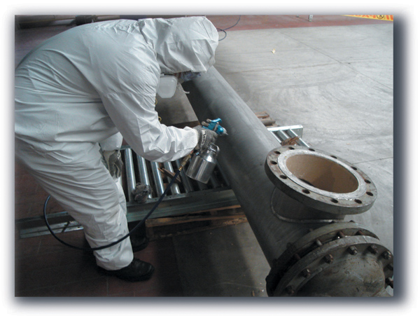
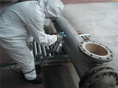
Instead of conventional refractory brick, G-5 refractory material is applied to the heating unit by spraying the material on the interior of the structure, which reduces the downtime for refractory replacement when compared to typical brick refractory materials. As is true with any thermal barrier improvement in refractory, G-5 improves the product to fuel use ratio. The material can be used in a variety of process heating applications including rotary kilns employed in the cement industry, boilers in the forest products industry, and furnaces employed in the metals and glass industries. This material was proven to sustain temperatures in excess of 2,000°F (1,100°C) and test results have been validated to 4,395°F (2,423°C) for over 12 hours.11 To learn more about this material and DOE’s involvement, please visit DOE’s Inventions & Innovations website, www.eere.energy.gov/inventions.
Advanced Nanoporous Composite Materials for Industrial Heating Applications
The Lawrence Berkeley National Laboratory, in a cost-shared partnership with DOE, has been researching new insulating composite materials for process heating applications. The result is the development of a low-cost nanoporous ceramic based on alumina, chromia, and silica. The material is an aerogel-based ceramic. This material can be synthesized using inexpensive chemicals as opposed to using the traditional expensive solgel alkoxide precursors, reducing the cost of the raw materials by two orders of magnitude.
In testing this material, it demonstrated approximately half the thermal conductivity as compared to the lowest density firebrick, thus providing far better insulation and reduced energy loss from the walls of the heating unit. The material also demonstrated only three percent shrinkage over nearly 2,000 hours (or 83 days) at 1,832°F (1,000°C) and only four percent shrinkage after 6,300 hours (or 262 days), demonstrating the uniquely extended life of the material. Shrinkage is important to monitor because it can create cracks and gaps in the refractory and exposes the shell of the heating system to high temperatures and corrosive materials. Swelling causes additional stress on the refractory bricks, which in turn can put more stress on the shell and lead to spalling of refractory. These nanoporous composites can be applied in a variety of industries that involve processing large quantities of materials at high temperatures, such as in the metals, chemicals, refining, forest products and cement industries.12 More information is available on the DOE’s Industrial Materials of the Future website at www.eere.energy.gov/industry/imf.
New Refractory Materials for Black Liquor and Biomass Gasification
One barrier to using gasification for black liquor is the need for refractory materials that can withstand the extremely harsh operating conditions of high alkali concentrations, elevated temperature of 1,742°F (950°C), and severe gas/liquid flow characteristics. This corrosive environment results in significant losses of refractory materials and metallic components, causing structural and safety issues, thermal efficiency losses, and unacceptable maintenance costs and downtime. The current short refractory lifetime in black liquor gasification makes maintenance costly and does not fit the scheduled mill maintenance, which typically runs on an annual basis.
Researchers from Oak Ridge National Laboratory, in partnership with DOE, developed improved corrosion-resistant refractories for gasifiers. The materials were developed by gaining a better understanding of the failure mechanisms of existing materials and using modeling to understand the fluid flow inside the gasifier. In 2004, new corrosion-resistant spinel refractory materials developed as a result of this research were installed in an operating black liquor gasifier unit. When the unit was shut down after one year for inspection and maintenance, it was found that the new refractory material did not require replacement. Although initially this material cost more than the traditional gasifier material, it proved to have a longer service life. Further, since the material did not break down under the harsh environment of the gasifier, it provided optimal insulation for the gasification process, saving energy costs in addition to maintenance costs. This material also has been shown to be able to operate at higher temperatures than tradition refractory materials, leading to an effective overall increase in energy efficiency. More information about this material and project is available at DOE’s Industrial Materials of the Future website, www.eere.energy.gov/industry/imf/.
Conclusion
The choice of refractory materials is dictated by the cost of installation and performance. In the past, it was good business sense to use low-cost, less energy-efficient refractory materials. However, with escalating energy prices, new refractory and insulation materials that were once considered expensive are now turning out to be good investments, promising significant reduction in energy bills. Manufacturers and equipment builders, therefore, need to continuously evaluate their thermal barrier options as new technologies emerge in the market and net gains from energy savings increase. Adopting the new and emerging barrier materials will assist manufacturers in lowering their energy bills and give equipment builders a competitive advantage. Maintaining an optimal thermal barrier of refractory material and insulation for process heating units provides manufacturers with that competitive advantage—saving manufacturers millions of dollars in lower energy costs, increasing productivity, lowering maintenance costs by avoiding unnecessary shutdowns, and increasing the capacity of a process heating unit.
Authors’ bios
Robert D. Naranjo, senior analyst at BCS, Incorporated, provides consulting and program support to the U.S. DOE, Office of Energy Efficiency and Renewable Energy, Industrial Technologies Program. He can be reached at rnaranjo@bcs-hq.com.
William T. Choate, group manager/senior technical staff, BCS, Incorporated, is a hands-on chemical engineer with over 30 years of engineering, R&D management, and consulting experience in the private and public sectors. He can be reached at Bchoate@bcs-hq.com.
Ehr Ping HuangFu is a technology manager at the U.S. DOE who oversees metalcasting and aluminum research under the Industrial Technologies Program. Contact him at
Ehr-Ping.Huangfu@ee.doe.gov.
References
1 Kwon, Ji Yea; Choate, William T., Naranjo, Robert D., “Advanced Melting Technologies: Energy Saving Concepts and Opportunities for the Metal Casting Industry,” U.S. Department of Energy, Office of Energy Efficiency and Renewable Energy, Industrial Technologies Program, Metal Casting Portfolio, November 2005: 7.
2 U.S. Environmental Protection Agency, “Global Warming ? Actions: Wise Rules” http://yosemite.epa.gov/oar%5Cglobalwarming.nsf/content/ActionsIndustryWiseRules.html#heat
3 Hemrick, James G., Hayden, H. Wayne, Angelini, Peter, Moore, Robert E., Headrick, William L., “Refractories for Industrial Processing: Opportunities for Improved Energy Efficiency,” U.S. Department of Energy, Office of Renewable Energy and Energy Efficiency, Industrial Technologies Program, January 2005: 5.
4 Based on the 2005 average industrial price of $8.47 per cubic feet. Source: U.S. Department of Energy, Energy Information Administration, http://tonto.eia.doe.gov/dnav/ng/ng_pri_sum_dcu_nus_a.htm
5 Industrial Technologies Program, Best Practices Subprogram, “Process Heating: Metal and Glass Manufacturers Reduce Cost by Increasing Energy Efficiency in Process Heat,” Fact Sheet, May 2004.
6 Rase, Howard F., and M. H. Barrow. Project Engineering of Process Plants. New York: John Wiley and Sons, Inc., 1957: 484.
7 Schwam, David, and Wallace, Jack F., “Melting of Aluminum Alloys State of the Art and Future Trends,” Case Western Reserve University, August 2005: 15.
8 Olchawski, James, “SPECIAL REPORT: Saving Energy with Microporous Insulation” http://www.ceramicindustry.com/CDA/Archives/a048ec0cf4ac7010VgnVCM100000f932a8c0
9 Schwam, David, and Wallace, Jack F., “Melting of Aluminum Alloys State of the Art and Future Trends,” Case Western Reserve University, August 2005: 16.
10 A program that provides financial and technical support to inventors and businesses for promising energy-saving concepts and technologies.
11 U.S. Department of Energy, Office of Energy Efficiency and Renewable Energy (EERE), Office of Industrial Technologies, Invention and Innovations, “Monolithic Refractory Material: High-Temperature Refractory Ceramic Saves Energy,” Fact Sheet, May 1999.
12 U.S. Department of Energy, Office of Energy Efficiency and Renewable Energy (EERE), Industrial Technologies Program (ITP), Industrial Materials of the Future (IMF), Advanced Nanoporous Composite Materials for Industrial Heating Applications: Improve Energy Efficiency With New Low Cost Nanostructured Refractory Material,” Fact Sheet, May 2006.
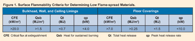
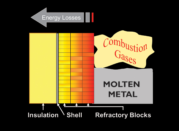 Figure 1
Figure One
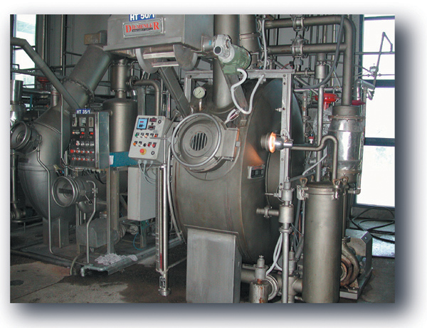
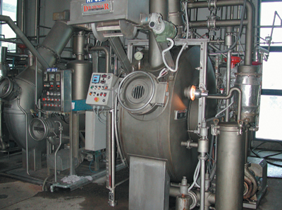
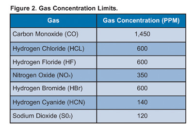
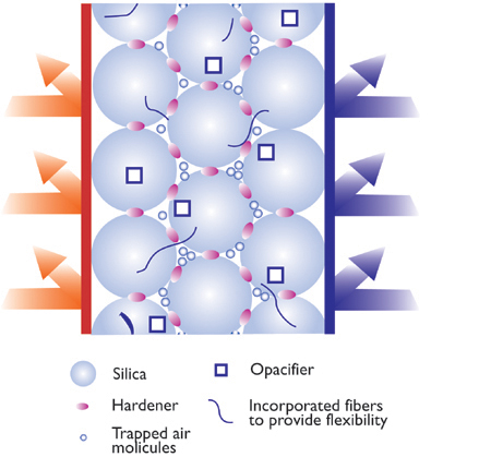 Figure 2
Figure Two