Case Study: Remediating Chilled-Water Pipe Insulation at a Football Stadium and Convention Center
Author’s Note: “While Hurricane Harvey was devastating to some regions of Texas, to the best of my knowledge, the buildings mentioned in this article were not flooded by Hurricane Harvey. Even if the stadium and convention center had flooded, I engineered an insulation system that does not absorb water, so the system should not be damaged by water.”

Chilled-water (CHW) pipe systems must be carefully insulated to perform properly—this is even more true in hot and humid environments. The challenges inherent in such an environment caused many unusual issues for a multiuse professional football stadium and convention center located in south Texas near the Gulf of Mexico. This case study will help readers:
- Understand the causes and effects of CHW pipe insulation systems operating beyond design conditions;
- Comprehend the long-term effects of “idle building syndrome” on the CHW pipe insulation installations;
- Clarify the physical effects that would identify the rationale for remediating the failed CHW pipe insulation systems; and
- Ascertain the type of pipe insulation systems that can be installed on a 38°F (3°C) functioning CHW pipe and require no external vapor retarder (VR) jacket.
The football stadium in question is a 1.9 million sq. ft. (176.5 thousand m2) air-conditioned structure with a seating capacity of ≥72,000 people and a retractable roof. Water-cooled chillers with up to 18,000 refrigerated tons (216 million BTU/hr.) capacity supplied the 24” NPS, 38°F (3°C) CHW supply piping underground to the stadium. The original specified/designed space conditions were 72°F to 75°F (22°C to 24°C) conditioned air at approximately 50% relative humidity (RH).
The adjacent rectangular-shaped convention center is 3/10-mile (0.5 km) long and has 1.4 million sq. ft. (130 thousand m2) air-conditioned floor space. The same 18,000 refrigerated tons (216 million BTU/hr.) capacity water-cooled chillers supplied the 24” NPS, 38°F (3°C) CHW supply piping underground to the convention center, with distribution piping across the 40 ft. to 80 ft. (12 m. to 24 m.) high exhibit hall ceilings to the mechanical rooms with air-handling units (AHUs).
Inside the stadium and convention center, the insulated CHW piping suffered from occasional exposures to the south Gulf Coast of Texas’s high humidity and ≥90°F (32°C) ambient conditions. In addition, all the 38°F (3°C) supply and 54°F (5°C) return piping operated constantly in all areas where it was located, as all areas were designed as conditioned air spaces. In other words, the chilled water supply and the chilled water return distribution piping are flowing 365 days a year.
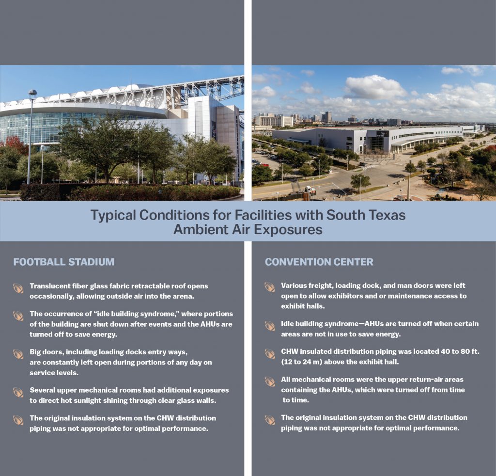
Although the stadium and convention center operated with 2 different types of CHW pipe insulation materials and accessories, both installation systems had several deficiencies and failed to perform to expectations. The following listed instances include installations practices, choice of materials and accessories, and specification requirements that led to some of the installed insulation system performance failures.
- The CHW pipe insulation was installed with insufficient thickness to prevent condensation from forming on the outer jacket surfaces. In addition, the same thickness was installed on the CHW pipe finished with aluminum jacket, which is an issue since the lower emittance of unpainted aluminum jacketing usually requires higher thickness requirements.
- The white paper–covered VR All Service Jacket’s (ASJ’s) longitudinal and circumferential joints were compromised during the formation of condensate water with poor lap closures and some staples. Consequently, some mold and mildew formed on a portion of the white paper ASJ jacket both with and without a PVC jacket.
- The PVC-covered insulation fitting wrap contained no vapor retarders or jacket and the fitting cover closure was sometimes held together with thumbtacks.
- Pipe insulation mitered fittings were covered with an open weave fabric and coated with a non-vapor-retarder mastic.
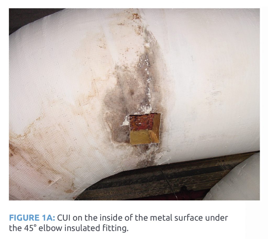
- All the original pipe insulations installed were permeable, allowing the insulation (with poorly performing VR seal) to become moisture laden from condensation, starting the corrosion under the insulation (CUI) on the CHW pipe, pipe fittings, flanges, flange bolts, etc.
- See Figure 1A: CUI on the inside on the metal surface under the 45° elbow insulated fitting.
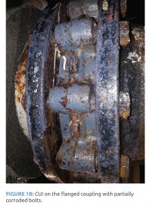
- See Figure 1B: CUI on the flanged coupling with partially corroded bolts.
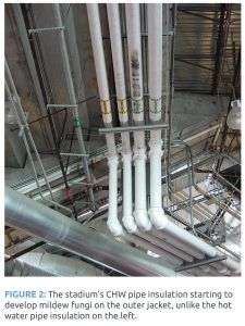
- See Figure 2: The stadium’s CHW pipe insulation starting to develop mildew fungi on the outer jacket, unlike the hot water pipe insulation on the left.
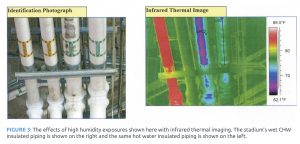
- See Figure 3: The effects of high humidity exposures shown here with infrared thermal imaging. The stadium’s wet CHW insulated piping is shown on the right and the same hot water insulated piping is shown on the left.
New CHW Pipe Insulation Engineering and Design Requirements
The multipurpose stadium and convention center are constantly being prepared for and hosting various events year-round, requiring the zoned air conditioning to operate 24 hours a day, 365 days a year. Therefore, the remediation process on all the CHW pipe insulation systems had to be conducted while the CHW supply and return piping were operating at 38°F (3°C) and 54°F (12°C), respectively. Unfortunately, isolating the CHW distribution piping for insulating at ambient temperatures is not possible.
All the new pipe and equipment insulation CHW systems are designed to sustain some condensation water forming on the outer pipe insulation surfaces due to the high humidity surrounding air conditions. This makes it important to use a nonpermeable insulation, such as cellular glass with a 0 permeance charcoal-colored VR butyl joint sealant; an insulation material with these specifications can withstand the formation of condensation without negatively effecting thermal performance.
In order to minimize the likelihood of condensation formation, the cellular glass insulation manufacturer provided the thickness requirements—as specified by the owner’s engineering design team—to accommodate 90°F (32°C) ambient air temperature and 90% RH, with no (0) wind, and with a 0.9 emittance PVC or CPVC jacket, or with no VR jacket. Originally no aluminum jacket was installed, but this was revised to PVC jacket inside the buildings and CPVC jacket and fittings covers for outdoor insulated CHW piping. In addition, the cellular glass insulation manufacturer warrants that, for a period of 20 years from the date of completion of construction (July 2016) the cellular glass installed on chilled water piping in the building identified herein will not absorb moisture, and will retain its original insulating efficiency, compressive strength, dimensional stability, and will remain noncombustible.
Installing the New Insulation System
Considering that the pre-2003 CHW piping installations used lesser pipe insulation thicknesses, the owner’s engineering group provided engineering drawing work-around solutions to accommodate the newly designed increases in pipe insulation thicknesses. The primary reason for increased thickness was due to changes in increased design requirements (e.g., designed conditions increased to 90°F and 90% relative humidity and a functioning VR system). Thickness was not the issue. Although the design conditions are very complex, the installation of a vapor sealed cellular glass pipe insulation system provided the only solution to the remediation process.
After removal of the original insulations and accessories, the 38°F (3°C) supply and 54°F (12°C), return pipe was cleaned, wire brushed, and hand dried while all the cellular glass longitudinal and circumferential joints, and vapor dams within the annular space, were coated with the charcoal-colored VR butyl sealant and quickly installed on the CHW pipe and pipe fittings. It must be noted that all saw cuts made on jobsite are made by movable flat table band saw (no hand saws allowed) to provide perfectly fitted joint cut surfaces. After the new pipe insulation sections were permanently installed, the cellular glass pipe insulation was banded together with stainless steel strapping.
Since the cellular glass insulation will not absorb water vapor/moisture and has a 0.0 perm rating, only the pipe section joints are sealed and no additional vapor retarder jacketing system is necessary for this CHW insulated piping system. White PVC and CPVC jackets are used primarily for another form of aesthetics or protection from physical mistreatment.
Figures 4–8 show the aesthetic difference between insulated CHW cellular glass pipe insulations with and without jacketing. These photos are the finished applications:
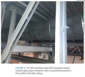
- Figure 4: 18” NPS stainless steel (SS) strapped sealed cellular glass pipe insulation with no jacketing located in the exhibit hall high ceiling.
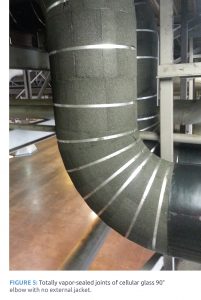
- Figure 5: Totally vapor-sealed joints of cellular glass 90° elbow with no external jacket.
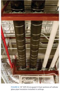
- Figure 6: 18” NPS SS strapped 3-foot sections of cellular glass pipe insulation installed in ceilings.
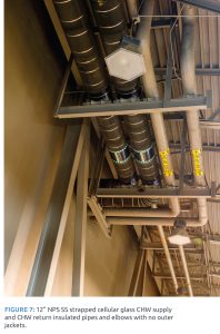
- Figure 7: 12” NPS SS strapped cellular glass CHW supply and CHW return insulated pipes and elbows with no outer jackets.
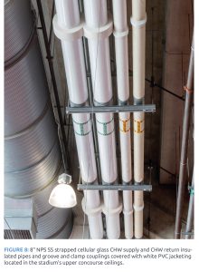
- Figure 8: 8” NPS SS strapped cellular glass CHW supply and CHW return insulated pipes and groove and clamp couplings covered with white PVC jacketing located in the stadium’s upper concourse ceilings.
Conclusions
There were several lessons learned on this project, prior to and during the remediation. It is critical for design engineers to consider and design the system for real-world conditions. Giving some thought to those conditions, and their impact on the long-term performance of the insulation system, pays dividends immediately. Consideration of issues such as “idle building syndrome” also pay dividends related to system performance. Choosing the most appropriate system based on real world conditions is important to achieving desired performance, as is making sure that any “value-engineering” processes actually add value. Finally, if remediation is necessary, choose an insulation system that is going to perform in the field considering all long-term local and surrounding conditions.
Copyright Statement
This article was published in the November 2017 issue of Insulation Outlook magazine. Copyright © 2017 National Insulation Association. All rights reserved. The contents of this website and Insulation Outlook magazine may not be reproduced in any means, in whole or in part, without the prior written permission of the publisher and NIA. Any unauthorized duplication is strictly prohibited and would violate NIA’s copyright and may violate other copyright agreements that NIA has with authors and partners. Contact publisher@insulation.org to reprint or reproduce this content.