Factors Influencing the Likelihood of Surface Condensation on Mechanical Systems Insulation, Part 1
Summary
One of the main purposes of insulation on pipe and mechanical equipment operating at below-ambient temperatures is to prevent condensation on the outer surface of the insulation system. Preventing this surface condensation is simple in concept: merely design the system to keep the surface temperature of the insulation system above the dew point temperature of the surrounding air. However, this simple relationship is made complicated because both temperatures are dependent on the interrelationship of a myriad of factors. All of these factors must be fully and properly considered or selected to assure optimum control of insulation system surface condensation commonly called condensation control.
Part One of this series from the July 2012 issue of Insulation Outlook discusses the influence of the design and climatic factors that affect condensation control. By understanding these variables, it is possible to identify the appropriate value for each factor and avoid some common mistakes related to achieving condensation control. Part Two, which ran in Insulation Outlook’s August 2012 issue, focuses on the practical application of this knowledge, with a discussion of the optimal design conditions and system components to reduce condensation in mechanical insulation systems.
Background
Pipe, tanks, ducts, vessels, and other mechanical equipment operating at below-ambient temperatures are insulated for various reasons, with a key one being to prevent condensation of water vapor from the ambient atmosphere on the exterior surface of the insulation system. Condensation can lead to numerous problems including the following:
- Safety hazards, as the water drips onto the floor below
- Damage to inventory, as the water drips onto the merchandise below
- Poor aesthetics when dripping water stains ceiling tiles
- Damage to the insulation system materials
- Reduced insulating ability of the insulation (increased k-Factor)
- Shortened insulation system lifespan
- Corrosion of jacketing or pipe
- Growth of mold on the insulation system surface or on other building materials where condensed water drips
Because of these potential problems, the prevention of condensation on the surface of cold mechanical insulation systems is of critical importance. This article will discuss the causes of surface condensation, the factors influencing it, and how to best identify design conditions and select system components to prevent surface condensation on mechanical insulation systems.
Various tables or charts are presented that show the insulation thickness necessary to prevent condensation under various conditions. These thicknesses were not generated through experimentation, but are based on common modeling or thickness calculations using the ASTM C680 standard thickness calculation method. This is the normal method for designing insulation thicknesses in the mechanical insulation industry. All of the thickness charts or tables presented assume that the material properties and ambient conditions are correctly known, but that is not always the case. These charts or tables also assume that the insulation system is working perfectly and is impervious to water and water vapor penetration, which is not always correct. However, these assumptions are useful and necessary for the purpose of this discussion. While the water resistance of various system components is important, especially in a cold pipe application, that is a subject for another time. There will be no discussion here related to which insulation or vapor retarder materials have better or worse resistance to water.
This discussion will be limited solely to insulating to achieve condensation control. Other design criteria, including meeting energy code requirements, achieving heat gain limits, maintaining temperature control, and freeze protection, will not be addressed.
The theory of surface condensation will be presented first, followed by the influence of climatic conditions and system components on surface condensation. Lastly, recommendations will be made on how to best work with climatic conditions and system components to prevent surface condensation.
Theory of Surface Condensation
Surface condensation occurs when water vapor in the air condenses on a surface that is below the dew point temperature of the surrounding air. This is a complicated topic when
applied to mechanical insulation systems because there are so many factors that influence either the dew point or the surface temperature of the insulation system. Figure 1 illustrates this concept and lists the various factors affecting each component of the equation. The factors shown in red will be discussed in detail.
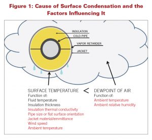
The system designer must understand this theory, select the appropriate design for climatic conditions and the proper insulation system components, and then determine the required insulation thickness to achieve the desired performance.
Influence of Climate Conditions
Ambient Temperature
The first climatic condition to be examined for its influence on insulation surface condensation is ambient temperature. Table 1 shows how insulation thickness has to be
adjusted to prevent surface condensation as the ambient temperature changes. This is shown for a very cold pipe at -80°F, as well as for a pipe at 20°F. The insulation material used for this table is Polyisocyanurate (PIR), which is specified by ASTM C591 as Grade 2, Type IV. The specific, constant conditions used for this table were 90% r.h., 7 mph wind, aluminum jacket with an emittance (Ɛ) of 0.1, and horizontal pipe. The pipe size, ambient temperature, and pipe temperature were varied as shown.
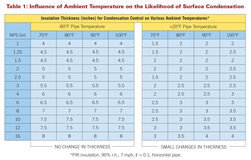
As Table 1 shows, a higher ambient temperature can lead to a slightly increased insulation thickness needed to prevent surface condensation, but this influence is small and only typically seen at higher pipe temperatures. For the system designer, this means that it is acceptable to determine the ambient design temperature only roughly; there is no need to
expend significant effort pinning down this design variable. While the ambient temperature plays only a small role in condensation control, it is a key factor in energy conservation and other design criteria, which are not addressed in this article.
Ambient Relative Humidity
The influence of ambient relative humidity (r.h.) on surface condensation is shown in Figure 2, which displays the insulation thickness necessary to prevent surface condensation, as the ambient r.h. changes. This is shown for a very cold pipe at -80°F, as well as for a pipe at 20°F. The insulation material used for these charts is again PIR. The specific constant conditions used for these charts are 90°F ambient temperature, 7 mph wind, aluminum jacket with an emittance (Ɛ) of 0.1, and horizontal pipe. The pipe
size, ambient r.h., and pipe temperature are varied as shown.
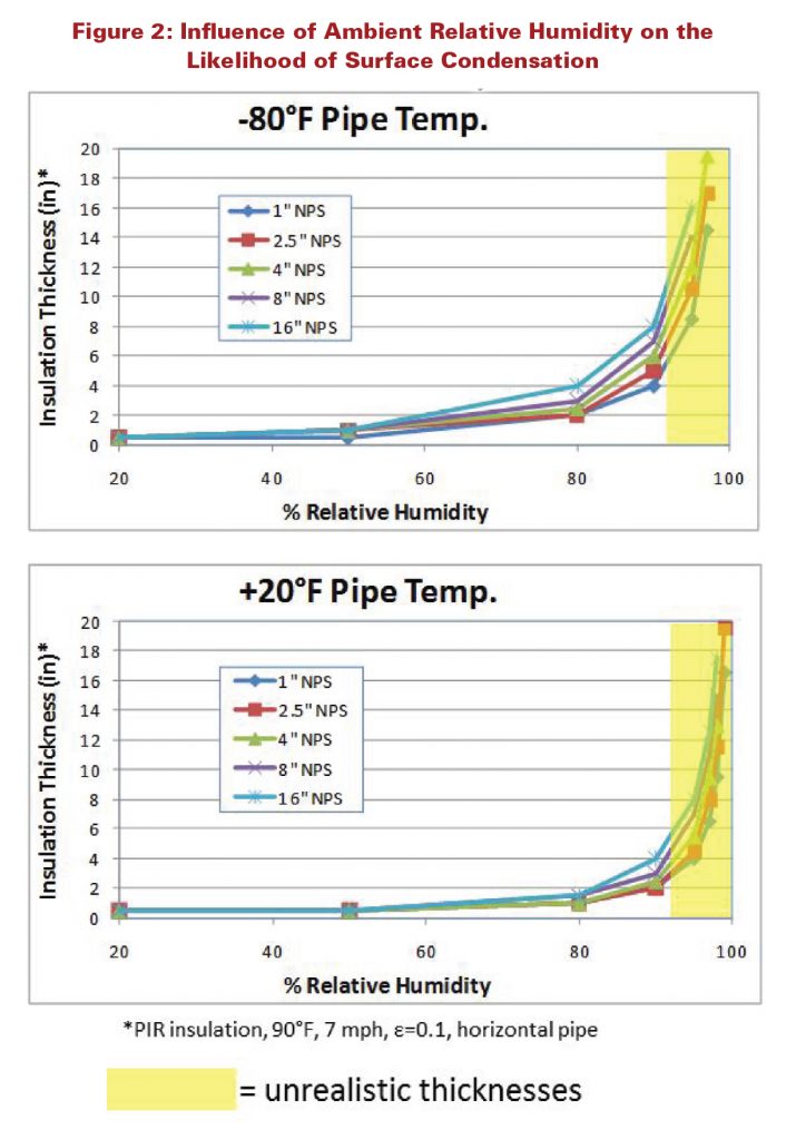
As Figure 2 shows, the influence of r.h. on surface condensation is very large, especially as the r.h. gets above around 70-80%. As the r.h. increases, the insulation thickness necessary to prevent surface condensation increases. This effect is present regardless of pipe size and pipe temperature, and is particularly pronounced at an r.h. above about 80%. It is important to note that the insulation thickness required to prevent surface condensation asymptotically approaches infinity, as the r.h. approaches 100%. In other words, designing a system to prevent condensation at 100% r.h. would require the use of an infinite thickness of insulation, which is obviously impossible. As a result of this asymptotic behavior, above a r.h. of around 90-95%, it takes an unrealistic and impractical insulation thickness to prevent condensation. This leads to a practical design limit for r.h. of around 90-95%.
In Figure 2 and many later graphs and tables showing insulation thickness, sections are highlighted in yellow to indicate “unrealistic thicknesses.” These are insulation thicknesses that the engineer/specifier would likely consider too large to be considered practical in the specified application. There would certainly be debate as to what thickness is considered “unrealistic,” and these yellow highlights are not meant to indicate some specific point at which insulation thickness becomes unrealistic. Rather, they are intended to help illustrate the concept that there are practical limits that play a role in the system design, in addition to theoretical factors.
Since most cold pipe systems are designed using a fairly high r.h., the influence of this factor is of paramount importance. Consider the five insulation system scenarios shown in Table 2 for the usually important 80-95% r.h. range. For each scenario, the insulation thickness required to prevent surface condensation is shown as a function of high percent, relative to humidity. As Table 2 shows, the insulation thickness required increases very rapidly above about 80-85% r.h., especially at colder pipe temperatures. Impractical insulation thicknesses are reached at 85-95% r.h., depending on the pipe temperature.

As the pipe temperature in an application gets colder, the specifier of an insulation system will typically reduce the r.h. or introduce other design features, such as higher jacket emittance, in order to avoid the need for unrealistic insulation thicknesses.
Ambient Wind Speed
In a cold pipe situation, the surface temperature of the insulation system will be below that of the surrounding atmosphere. Wind will increase the rate of heat transfer and warm
the insulation surface, thus leading to a reduced likelihood of surface condensation. The influence of wind speed on surface condensation is fairly large but reaches diminishing returns above the 5-7 mph range. Table 3 shows the influence of wind speed on the insulation thickness required to prevent condensation for several scenarios. As Table 3 shows, the required insulation thickness increases at lower wind speeds and is especially high at zero wind speed.

When considering the influence of wind speed, remember that 0 mph is also a speed, and in most indoor applications, the wind speed will indeed be zero. In outdoor applications, it is typical to assume the presence of some wind when designing an insulation system. A commonly assumed wind speed in the industry, when there is not a specific reason to use a higher or lower value, is 7 mph.
Now that we have discussed the climatic design conditions, the next category of factors to examine is the system components and their influence on surface condensation.
Influence of System Components
Jacket Type—Emittance (Ɛ)
Emittance is an important factor in the radiative component of heat transfer and is defined in ASTM C168 as, “The ratio of the radiant flux emitted by a specimen to that emitted by a blackbody at the same temperature and under the same conditions.”
This is certainly not as simple to understand as wind speed or ambient temperature. Emittance ranges from 0 to 1, with lower values representing materials that have a comparatively low ability to transfer heat through radiation (such as aluminum or stainless steel metal jacketing) and higher values representing materials that have a greater ability to transfer heat through radiation (such as plastic, paper, and other non-metallic
surfaces).
It is important to note that emittance is not the same as solar reflectance. In solar reflectance, the color of the jacketing is important. A black-colored, plastic jacket would have a much lower solar reflectance than a white jacket and would, therefore, absorb more heat from the incident sunlight. In emittance, the color of the jacket has a minimal
influence. A black, plastic jacket might have an emittance of 0.92, while a white, plastic jacket might have an emittance of 0.90, which is an insignificant difference.
Table 4 shows the influence of jacket emittance on the likelihood of surface condensation. Jacket materials with lower emittance, like most metals, yield a colder outer surface, making surface condensation more likely and increasing the required insulation thickness. Materials with higher emittance, like paper, plastic, or mastic, yield a warmer outer surface, making surface condensation less likely. This has a significant effect on the insulation thickness needed to prevent the condensation from occurring.

PVC jacketing is not typically recommended for outdoor use, due to sensitivity to ultraviolet light, and is included in Table 4 to illustrate the impact of using jacketing with high emittance on insulation thickness. The use of painted metal jacketing in outdoor applications is an often overlooked, but is a good way to reduce the required insulation thickness by raising the jacket emittance.
Insulation Type—Thermal Conductivity
The insulating ability of the insulation material used has a significant impact on the likelihood of surface condensation and the insulation thickness necessary to prevent this
condensation. There are many ways to characterize insulating ability. The most common in the North American mechanical insulation industry is the thermal conductivity (k-Factor) at 75°F mean temperature. This simple characterization is useful when discussing insulation materials but should not be used in calculating actual thickness or other heat transfer calculations. The often complicated relationship of thermal conductivity to mean temperature requires that any heat transfer calculations should be completed using this actual and full curve, not a single-point representation of this curve, such as the 75°F value. When comparing the k-Factor, note that a lower value is better. Table 5 shows the k-Factor of several mechanical insulation types at 75°F mean temperature, which is taken from the respective ASTM material standards.
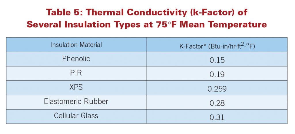
Of course, there are many properties besides k-Factor that should be considered when selecting an insulation material, including cost, water resistance, flammability, availability, and more. Nonetheless, the insulation material used, and its thermal conductivity, has a direct, strong impact on the thickness required to prevent surface condensation and must be considered when selecting an insulation material and determining insulation thickness.
Table 6 shows the strong influence of the insulation thermal conductivity on the insulation thickness needed to prevent surface condensation. As the thermal conductivity goes down (gets better), the required insulation thickness also decreases.

System Geometry—Pipe Size and Flat Surface Orientation
The last factor to be discussed is the geometry of the system, meaning the NPS for pipe scenarios and the orientation of the surface for flat tank or duct scenarios. The cold flat
surface can be vertically oriented; horizontal, facing downward; or horizontal, facing upward. The influence of the flat surface orientation is a phenomenon that is often overlooked, leading to the mistake where all surfaces of a tank or duct are insulated with the same thickness. In reality, the convective component of heat transfer is different in each of these orientations, thus requiring different insulation thicknesses for each orientation. The difference in convective heat transfer is caused by the cold-air-sinking and
hot-air-rising phenomena, coupled with the possible interference of this movement by the tank or duct. As an example, on the top of a tank or duct, the cold air next to the surface of the insulation system should naturally sink, but it is “trapped” by the presence of the duct and insulation system below it. This causes the cold air to stay longer than usual at the insulation system surface, which leads to a colder insulation system surface and a greater tendency for condensation on this surface. To account for this, the insulation thickness on that top surface must be increased.
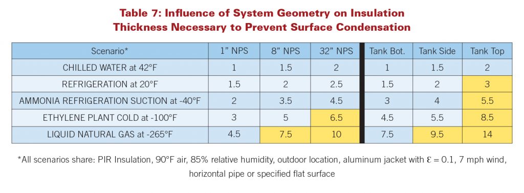
Table 7 shows the influence of pipe size and flat surface orientation on the insulation thickness required to prevent condensation. As the pipe size (NPS) increases, the insulation thickness required also increases. This effect grows in significance at colder pipe temperatures. The insulation thickness required on cold, flat surfaces is greatest on the top of a tank/duct, lowest on the bottom, and intermediate on the sides.
Summary of the Influence of the Various Factors
The influence of all the factors on insulation thickness is summarized in Table 8, which also shows a qualitative assessment of the magnitude or size of the effect of each factor.

Another way of summarizing the influences is to categorize the factors as either helpful—they reduce the likelihood of condensation or reduce the insulation thickness required to prevent condensation—or harmful—they increase the likelihood of condensation or increase the insulation thickness required to prevent condensation. This is shown in Figure 3.

When examining the impact of a design condition, the size of this effect must also be considered. For example, more care should be taken in considering r.h. than in ambient temperature, due to the former having a much larger effect.
References:
- J. Young, “Preventing Corrosion on the Interior Surface of Metal Jacketing,” Insulation Outlook, November, 2011.
- ASHRAE 2009 Handbook of Fundamentals, Chapter 23, p. 3.
Note: This article is based on Jim Young’s presentation at the
NIA’s 57th Annual Convention. He will also be presenting this
information at the RETA National Conference & Heavy Equipment show on
November 6-9, 2012. Information about this presentation can be found at
www.reta.com/convention/2012/index.html. © Copyright ITW Insulation Systems
2011.
