Category Archives: Material Selection

Don’t consider insulation a ‘cost’! When properly done, the insulation of your facility doesn’t add cost to the product the facility produces. It saves operating expenses, thus allowing the owner/manufacturer to become more competitive in the market. An insulation system can actually pay itself back and then continue to earn savings of energy during operation. This can be translated directly to increased efficiencies in the plant, a lowering of expenses, and potentially an increase in market share with a gain on profits earned.

Since the beginning of time, insulation in one form or another has been a part of everyone’s lives. The basic idea of keeping something hot or cold has evolved into the need to conserve energy, protect personnel, reduce operating costs and reduce emissions; thus becoming a very important part of all construction projects. Yet, we often see insulation as one of the project line items where corners are cut.

Trying to digest all of the milestones that the insulation industry has reached is quite a task. The emergence of new and improved insulation materials and products to protect the insulation is something that our entire industry strives toward. It is something for which we all can be proud. When so many materials meet the majority of the criteria of consideration for installation, the difficult task is determining not what type of insulation could be used, but what type of insulation should be used in a specific application. With rising energy costs and the need to reduce energy and emissions, a properly insulated system has never been more important.

How can this be done correctly? Insulation manufacturers, fabricators, contractors and distributors have all become more involved with the selection of materials for a specific project. We have the responsibility to assist in helping make the correct choices in all aspects of the insulation selection and application process. Being involved means being accountable. It means becoming aware and understanding a lot of hidden details that are sometimes not so obvious, but are very important to the efficient operating of an insulation system.

Materials

The term "high temperature market" means different things to different people. You may be surprised to find that 80 percent to 90 percent of the above ambient operating systems, whether commercial or industrial, operate at 300 degrees Fahrenheit (F) or below. And it may be of interest to note that for example, only about 20 percent of the piping in a power plant may exceed 350 degrees F. For the purpose of this article, let’s assume that high temperature can refer to pipe operating temperatures to 450 degrees F. Above 450 degrees, many different considerations must be examined that will not be part of this article. The most common pipe operating in the above ambient range to 450 degrees F is steam and process piping. These are primarily found in the industrial market, such as chemical, petrochemical, pharmaceutical, power and refining.

Fiberglass, mineral wool, calcium silicate, ceramic fiber, perlite, cellular glass, removable covers and more recently, high temperature polyisocyanurate, all state that their maximum operating temperatures are good to 450 degrees F, or above. Preformed or fabricated, these insulation materials are readily available. But what other factors should be considered for hot applications today?

System Design-Avoidable Mistakes

It sometimes seems that insulation is an afterthought. Contributing factors to this may be because the insulator is one of the last trades on the project, or that on a new construction project the line item cost associated with the insulation system is a small part of the total project.

As an industry it’s critical that we promote involvement with owners and their engineering and design firms at the very beginning of the process if the insulation system is to function properly. Before an insulation material and jacketing system can be chosen, many parameters must be considered. Common problems associated with failed insulation could be avoided if the substrate could be designed to allow for the proper insulation application.

Too often we run into obstacles in the field that end up jeopardizing the insulator’s ability to properly insulate the system. What job sites have you walked through and found the following:

  • Pipes that aren’t spaced far enough apart and don’t allow for the correct insulation thickness to be installed, nor enough room to work and provide a good installation of the insulation.

  • Flanges, valves, elbows and other items installed too close together, making it impossible to properly insulate.

  • The use of valves that don’t have extended bonnets on them to allow for the correct insulation thickness under the valve handle or allow for maintenance of the valve.

  • I beams, braces, brackets and other items coming in contact with the pipe, causing a thermal short.

  • Gauges, pipes, and man-way doors installed too close to the vessel or equipment, making it impossible to insulate around or above.

  • Improper type of pipe support used.

  • Pipes not primed before insulation is installed because it was never specified.

Are these items pipe system design problems, pipe installation problems or a combination? The reality of most construction projects is that while the best (or worst) of design and drawings may be provided to the general, and thus to the mechanical contractor; many projects require changes in the field. This is where good communication with the owner by the engineer to the general to the mechanical is imperative.

Involvement that includes the insulation contractor may facilitate proper installation.

Material Selection

Criteria for selecting insulation material should include the reason for insulating. In the high temperature market, the primary reason for insulating a process line is process control. Insulation may be extremely critical to the process. For example, some processes may only allow for a minimal temperature fluctuation. Erratic performance of the insulation may be extremely costly to the owner because the process was compromised.

Most other piping is insulated to protect personnel or to provide an acceptable heat loss.

Once the lines to be insulated have been determined and the ultimate goal of the insulation installation is understood, it’s important to take time and review the material and jacket systems that are being chosen for a project. Whether it’s an engineer starting to design a project, an end user trying to determine what he wants or a salesperson trying to sell an insulation material, the technical information should be reviewed thoroughly.

Each manufacturer publishes test data for the product it makes. They typically list physical properties such as thermal conductivity, compressive strength, density, temperature range and flame and smoke development. Each characteristic has a direct bearing on the insulation product’s ability to perform properly during operation of a given process or application at its service temperature. It’s quite an undertaking and almost impossible to directly compare all the materials listed earlier.

The testing organization ASTM had the daunting task of developing methods to test materials. As each of the materials are so different in composition, i.e., some fibrous, some rigid, some cellular, etc., in many instances, ASTM had to develop completely different tests, or different methods within a given test, for the same physical property because of differences between types of materials. The following are several examples of which you may or may not be aware:

In the instance of identifying the actual compressive strength characteristic of a product, ASTM has a different test method to measure a fibrous material, a different method for a cellular glass, cal-sil, etc. Each product has a compressive strength, however, none of the materials can be judged by one encompassing test.

Many ASTM tests contain several methods of testing within the test for a specific physical characteristic. In the example of water absorption, there are six methods within, all identified by one main test number. It’s of interest to note that one product sample, cut into six pieces and exposed to each six test methods, will not yield the same result.

In the past, people involved with industrial applications have not been as concerned as those involved with commercial installations in regard to the flame and smoke rating of a product. However, this has been changing over the years as plants continue to improve all safety aspects of their facility. Many products with a 25/50 rating at 1 inch thick doesn’t meet the 25/50 rating at a greater thickness, as in two layers of 1 inch each on a pipe. It’s important to network with the manufacturer regarding your materials of choice to identify the flame and smoke rating for the specified thickness of insulation required of the project.

Calculating thickness for a specified heat loss or surface temperature requires comparison of thermal conductivity of the insulation. Most ASTM test methods are based on an oven -dried sample tested at 75ºF mean temperature. What is important to know when designing the system, is the K Factor at the ‘operating’ temperature. It will be different than the published value.

In addition, it’s important to find out what happens to the insulation product at the elevated operating temperature for all of its physical properties. There are two ASTM tests that measure a host of physical characteristics of the product, 1) while in-service at higher temperatures and 2) after it has been in-service for a specified length of time. These two tests identify the insulation’s ability to perform at in-service temperatures. It’s interesting to note that most insulation materials perform differently compared to their data sheets, all properties at 75 degrees F mean, when compared to system operating temperatures. This isn’t a bad thing. These tests are only provided to increase awareness. During the design phase, identifying and addressing potential problems, such as shrinkage or warping, allows the engineer to build safety factors into the system such as double layer applications and expansion/contraction joints to provide a system that’s not doomed from the start.

Couple the differences of testing and test methods with the fact that manufacturers don’t have a standard listing of test results to report on their data sheets and one realizes that real comparison requires a good understanding of products and testing methods and the ability to read between the lines. Analyze how all of this information effects the application as well as how it changes when applied to the temperature of the system being insulated.

Fabrication of High Temperature Materials

Fabrication plays an important role in application and function of an insulation system. From the proper fabrication of elbows, flanges, valves and pipe supports, to the manufacture of insulation for large diameter pipe or small vessels. Attention to proper miter spacing ensures a proper fit in the system; both in closure around the pipe and/or fittings inside of metal covers.

Careful attention must be taken to all details of the fabrication process, including that of meeting exacting tolerances, in order to maintain the integrity if the insulation. Once again adhesives that glue the materials together are very important. Compatibility with the insulation as well as attention to flammability with the system must be considered.

For example, cellular glass is often glued together to make fittings, valve covers and other components. There are two basic means to adhere the cellular glass sections together: hot asphalt or gypsum cement. Both products have their own limitations. The cement shouldn’t be used on a cold system unless liquid nitrogen, and the asphalt can soften at 250 to 300+ ºF. If asphalt is used to adhere insulation miter sections together to make a fitting for a system that’s operating at 450ºF or above, the system will fail because the operating temperature is too hot and will cause the asphalt to melt. At the higher temperatures, the gypsum cement should be applied.

Another consideration when fabricating fittings of fibrous glass is the adhesives used to glue mitered fittings. The end service temperature isn’t always known. Adhesives that work well at lower temperatures aren’t advised at higher service temperatures. If the adhesives aren’t suited to the operating temperature, a flashing of the adhesive may occur; expelling smoke to the atmosphere and/or subsequently, the glue evaporates and the insulation falls away from the pipe. This provides another thermal short in the system, increasing energy expense and usually provides another location for water ingress.

Altering the insulation structure can have important implications. Most fibrous pipe insulation fibers wrap the pipe, i.e., the insulation runs parallel to the pipe or substrate. These parallel fibers create air gaps that improve the insulation’s thermal properties. If the fibers are cut and then installed perpendicular to the pipe it will not function as efficiently, as there is now a flow of air directly away from the pipe.

Compatible Components

Just as important as the insulation choice is to the project, the use of accessory items is to the insulation. Everything must align and mesh together to perform properly. Coatings, adhesive sealants, and claddings all must be compatible with each other and the operating conditions of the system. They must be able to hold up to the same conditions as the insulation. Each one should be reviewed and carefully assessed. If one of them fails to perform properly it will jeopardize the integrity of the total installation.

While this is an article on insulation materials in high temperature service, not only insulation and cladding can be considered. This must be coupled with the expansion of the pipe/vessel at the service temperature. Coefficients of expansion or contraction of the insulation material at the service temperature must be known. Most insulation products will shrink with heat; while the pipe expands with heat. Properly installed expansion/contraction joints and supports are a must. In addition, double layer insulation can help alleviate bare or hot spots between insulation sections.

Final Design Considerations

As the No. 1 enemy of any insulation system, whether hot or cold, is water; all choices for the system must be reviewed to make sure that the system is breathable, yet water-tight. Additional lines of defense against water should be incorporated into the total design.

It’s a misnomer that water can’t be found in the insulation of a hot service line. Water ingress can be noted under improperly installed or maintained jacket laps, improper spacing of jacket ends, at fittings, flanges, valves and other areas. As we are discussing high temperature lines of pipe to 450 degrees F you may note that through the thickness of the insulation, heat is dissipated to the surface of the insulation. To meet minimum surface temperatures of personnel protection; approximately 110 degrees F, the thickness of insulation will experience a temperature gradient from 450ºF to 212ºF, which is below that of steam, to 110ºF at the surface. The thickness of insulation that can be identified from 212ºF to 110ºF at the surface, is where water can be retained in the insulation.

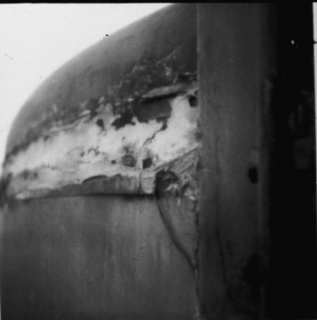
Left in operation, yes, this portion can be dried, but at what expense? With the next rain, water will enter the system. The resulting expense isn’t only an increase in energy required to dry the system, but the added danger of a raised surface temperature. Remember, water is a conductor, not an insulator. The surface temperature may now exceed what is safe for personnel. And, as systems are continually taken out of service for maintenance, impurities from the atmosphere will travel via water through the insulation to the pipe surface layering salt and other corrosive elements under the insulation. Corrosion under insulation is a large destroyer of the expensive piping substrate and a huge expense to the owner. Continual maintenance is essential and a proper piping primer for the operation temperature applied to the pipe will help increase the service life of the pipe.

Positive Payback

Insulation is the only expenditure that the owner incurs that actually earns him a payback. When reviewing and comparing potential installation choices, the lowest price at installation isn’t always the most economic choice. Adequate insulation thickness, such as design for a minimal heat loss as opposed to design for thickness that will protect personnel (i.e. usually less thickness), can reap the owner instant rewards as well as continual rewards over the life of the installation. Most insulation manufacturers are able to provide an energy analysis and a return on the owners investment in insulation based on the design criteria and current energy costs.

The key is coordination. Insulation manufacturers, fabricators, distributors, insulation contractors, mechanical contractors and designers/engineers must educate the owners about the benefits of a system that can help them be more competitive in their marketplace. We all share in the responsibility of working together throughout the entire insulation process. It’s the expertise and the experience of everyone in the industry that can help insure that the insulation system(s) can be properly designed, installed and maintained.

Scott Weiss is no stranger to large construction projects. As a vice president at Kamco Building Supply, Weiss has visited many big building sites over the years. Still, he was impressed when he first saw the new Washington Convention Center in Washington, D.C.

"When we first saw the project, it was a tremendous hole in the ground," said Weiss. "The excavation was so large the crane work and construction equipment actually looked like Tonka toys in there."

No wonder. The new Washington Convention Center is the largest public works project in the District since the city was first constructed. It will be the largest building in Washington and is being built in the largest excavation in the Western Hemisphere. To get the space they needed without violating the District’s strict limits on building height, the 17-acre site was carved out to 50 feet below ground level. It covers approximately six city blocks in the downtown business district.

To give you an idea of how much space the structure will enclose, the Sears Tower could comfortably fit inside. In the main exhibit hall, four 747s could sit on two major league baseball fields or six football fields. The new center will use as much steel as seven Eiffel Towers.

Scheduled for completion this spring, the new Washington Convention Center will contain 2.3 million square feet of floor space, attract an estimated 2.5 million visitors, and is expected to bring $1.4 billion in community economic stimulus each year. The new center is almost three times as large as its predecessor, a concrete box of a building just a block away. When that 800,000-square-foot facility opened in 1983, it was the fourth-largest convention center in the United States. But by 1997, a nationwide convention-center boom left the District far behind, dropping its center to No. 30.

In short, the new convention center will be a monumental building worthy of the nation’s capital. Located in a neighborhood with interesting facades, the building will complement the surrounding townhouses with glass, brick, limestone and granite. At night, it will be a big lantern to the city. Grand light-filled spaces will usher visitors to meetings or exhibits.

Topping it all off will be the largest ballroom (52,000 square feet with a dinner seating capacity of 5,000) on the East Coast with a panoramic view of Washington’s impressive monuments. The facility is the culmination of more than 10 years of effort, from a financial feasibility study begun in 1992 to a groundbreaking ceremony in 1998 to the completion of the steel framework in 2001.

Working quietly and efficiently to conserve energy and keep everyone comfortable inside the building will be a variety of insulation products, including extruded foam insulation and a variety of commercial and mineral wool insulation products.

Owens Corning provided much of the insulation products for the building. Advanced Specialty Contractors, Jessup, Md, installed them.

Kevin Sisk, construction superintendent for Advanced Specialty Contractors, said they used more than 25 truckloads of material on the project. "There were about 400 rolls of duct wrap and the rest of it [was] pipe covering."

No stranger to large projects-Sisk also worked on the National Archive in Adelphi, Md., which included 10 buildings in a single endeavor-he admitted that the convention center is special. He said the challenges were the same as any other job, but were magnified by the fact that the convention center is two city blocks wide and six city blocks long.

"It’s just like it is anywhere else these days," says Sisk. "They are all challenging, but in this case the amount of material and the movement of materials is especially challenging. And everything is up in the air; quite high, as a matter of fact. A lot of the work on the job [had to be] done out of lifts; there is very little ladder work on that entire job."

Kamco Supply Corp. supplied the interior package and exterior framing. Weiss said his company supplied more than a million square feet of insulation products, including both fiber glass and mineral wool insulation. Applications include sound attenuation, fire safety and thermal performance.

"It’s an enormous undertaking," said Weiss during the construction process. "It’s going to take quite a bit of manpower to supply. It’s a good job for us. The steel framing and interior metal [totaled] about 3 million lineal feet. The drywall alone is about 6 million square feet.

"We haven’t even scratched the surface yet," he said early in the construction phase of the project. "We’ll be down there every day for at least a year and a half."

A Road Runs Through It

One special feature of the new Washington Convention Center will be an underground plaza goes right through the middle of the building. There will be exhibit and meeting space above the plaza, and a heated work area below. Exhibitors and others will be able to bring tractor-trailers into the center of the building to unload their displays and convention supplies.

Because parts of the plaza will be exposed to the elements and have a heated area under it, contractors poured concrete over foam insulation. Workers first poured a concrete slab floor, then added a hot-fluid-applied waterproofing membrane, topped that with foam insulation, and then poured a topcoat of concrete.

"It’s a roadway that’s also a roof," said Steve Gordon, sales representative for Owens Corning Foamular insulation. "That’s really what it is. They have to insulate the plaza deck because there is heated space under it."

Gordon says the job was originally designed for 60-pound board, but there were concerns about the compressive strength of the material. "We worked with the architect and engineer to change the specification. That was about a four-year project."

As a result, there’s about 400,000 square feet of foam insulation in plaza decks at the new convention center.

The foam insulation offers compressive strength of 100 pounds per square inch. It’s designed for use in high load-bearing applications and is ideal of under slabs, concrete floors and over foundation walls. The superior water resistance of extruded foam insulation also assures stable thermal performance.

Foam insulation is also being used in two other applications, as perimeter insulation around the foundation, and in the wall cavity behind the exterior brick veneer.

Strong Relationships

Large projects always require good working relationships among everyone involved. The new convention center is no exception.

"A job like this is an ongoing project; it’s not just a one-shot deal," said Weiss "There needs to flexibility in schedules, flexibility in delivery times, and there has got to be communication back and forth. We’ve had a long-standing relationship with [Owens Corning]. If there is a problem, we can get together with them and work it out."

The convention center was scheduled for completion by March 2003 with a budget estimate of about $800 million. And with an assist from insulation, convention goers are sure to be comfortable and cozy in the new building.

Thermal insulation provides many uses in industrial (power and petrochemical) and commercial applications. In this story, we will only discuss industrial applications. In simple terms, thermal insulation reduces heat flow from one surface to another. For hot (above ambient) applications, thermal insulation reduces heat loss. On cold (below ambient) applications, the insulation generally serves to minimize heat gain.

In some cases, the application design purpose may seem unrelated to heat loss or heat gain. However the net result is that heat transfer is reduced. Examples of this are insulation for personnel protection and condensation control (sweating). In personnel protection, enough insulation is provided to keep the surface below a given temperature. For condensation control, enough insulation is provided to keep the surface temperature above the dew point. In both cases, insulation is used to control the surface temperature for a desired effect other than thermal conservation. The effect, however, is that in both cases heat transfer is reduced to maintain the surface temperature at a given design criteria.

Correctly designing and specifying an insulation system is much more involved than just selecting a particular material. An insulation system is any combination of insulation materials used in conjunction with mastics, adhesives, sealants, coatings, membranes, barriers, and/or other accessory products to produce an efficient assembly to reduce heat flow. Frequently, the design of insulation systems can either determine or direct the ultimate performance of the process. Improperly designed insulation systems are subject to damage and degradation. Degradation will compromise the material’s performance characteristics, and in many cases the entire process for which the insulation system was designed.

There are many different types of insulation materials available. Each has its own set of properties and performance characteristics. And for each insulation material available, a correct application procedure and corresponding accessory material(s) or "system" application is available. The single most important thing to remember is the word "system." This refers not only to the insulation materials, but also the application and finish.

When asked to supply an insulation specification for a power plant or process plant, several questions must first be considered before design can start. Some examples are:

  • What are the temperature limits of the items to be insulated?
  • Where is the plant geographical location and what are the environmental conditions?
  • What fluids are being insulated?
  • Why is insulation required?
  • What type of insulation material should be used?
  • What type of finish is necessary?
    What Are the Temperature Limits?

What are the temperature limits for insulated items? This starts the entire design and material selection. For a power plant, it’s usually in a range above 32 degrees Fahrenheit (F) to about 1,200 degrees F. At an ethylene plant, the range is between minus 250 degrees F and 1,200 degrees F. This requires two very different types of design considerations, although the materials and application for the 32 degree F range and 1,200 degree F range could be the same. This also necessitates the need for expansion and contraction joints.

The design of hot service insulation expansion joints and insulation supports are quite important. In steam system design (1,000 degrees F) the piping would expand .095 inches per foot of pipe, and the insulation (calcium silicate or perlite) would contract .024 inches per foot. A total of 5.95 inches of expansion must be accounted for if the pipe length was 50 feet. The pipe expansion must still be accounted for, even though some materials will not contract (such as mineral wools). It’s also important to control where the expansion will occur. On vertical piping and equipment, this is done with the use of insulation/expansion supports. Without these, all the expansion will occur at the top.

In cold insulation design, contraction joints are just as important as expansion joints are to hot insulation. If the system has an operating temperature of minus 100 degrees F, the pipe (stainless steel) will contract 0.0176 inch per foot and the insulation, depending on the material, will contract 0.01 inch per foot for cellular glass insulation to 0.102 inch per foot for polyisocyanurate insulation.

Geographic and Environmental Factors

Geographic design considerations depend on plant location. Facilities located in hot and humid climates will have different parameters than those located in a dry, cooler climate. The National Weather Bureau, the American Society of Heating, Refrigerating and Air-Conditioning Engineers, Inc., U.S. meteorological services, sited data or similar service provides local weather data, which can be used in determining the minimum, maximum and average daily temperatures, wind, humidity and rainfall.

Review of the following parameters should give the necessary design data:

  • Wind
  • Snowfall
  • Extreme temperatures
  • Relative humidity
  • Rainfall
  • Water table
  • Seismic readings

It’s important to know if a plant location is near an industrial complex, where potentially corrosive chemicals are present, or near coastal areas, which can affect the selection of insulation and weatherproofing materials along with application procedures. Insulated equipment located near a cooling tower or ash handling equipment will be exposed to a more corrosive environment than will the other plant equipment.

Wind conditions (both positive and negative [back side negative pressure]) must be considered in insulation design. In hot service, the weatherproofing could be supported off of angle irons attached to the vessel or vessel support system. The insulation material could be rigid enough to support the positive pressure of the weatherproofing, but the attachments must be strong enough to resist the negative pressure on the backside. Corrugated metal is usually preferred on vessel sidewalls held in place with stainless steel bands on 18 inch centers and screws in the vertical overlapping seams.

What Fluids Are Being Insulated?

Insulation design for pipe and equipment that handles hazardous chemicals such as flammable or toxic materials requires special consideration in selecting insulation materials, weatherproofing materials and application methods.

Insulation materials that can absorb fluids (such as hot oils/heat transfer fluids) and cause that fluid’s flash point to be reduced shouldn’t be used in such service. Non-absorbent type insulation materials should be used in these services.

Non-absorbent type insulation materials may also be required for toxic services, where trapping of a toxic substance in the insulation can pose health hazards.

Why Is Insulation Required?

Why is insulation required? Because it’s necessary! But the real question is, is it necessary to limit heat loss, for personnel protection, to reduce heat gain, to limit surface condensation, to provide process control or for product stabilization, freeze protection, noise control and fire protection? Each of these may require different thickness, materials, finish and extent of insulation.

Limit Heat Loss or Heat Conservation

Insulation by itself will not maintain or hold temperatures within a system. Insulation can only provide a means to limit, conserve, control, reduce, or minimize the rate of heat flow through a system. But it can’t stop the process. Insulation is merely a heat flow reducer, not a barrier to heat flow.

It might be that condensate and blowdown lines to drains or holding tanks may require insulation to limit heat loss, but heat losses through valves and flanges isn’t critical to the system; therefore they’re not insulated (although personnel protection may be required).

Personnel Protection

When designing insulation systems for personnel protection, only enough insulation shall be used to reduce the surface temperature to an acceptable limit to prevent individuals from getting burned from the surface. Traditionally, the insulation surface’s upper temperature when designing for personnel protection is 140 degrees F. To date, no mandates or statutes govern the upper limit for personnel protection. Refer to "ASTM C1055 – Standard Guide for Heated System Surfaces Conditions That Produce Contact Burn Injuries," for guidance in selecting acceptable temperature limits.

Insulation for personnel protection is generally applied only in those areas accessible to persons during normal plant operation and maintenance, and applied to a high of 7 feet above or 3 feet from platforms or work areas.

In some system designs where there’s no justification for insulation, and the insulation could actually be detrimental to the process, fabrication guards may be employed to provide personnel protection.

When insulation is used for personnel protection, it’s very important to flash the ends to prevent water or moisture from getting behind the insulation, and to prevent insulation deterioration and surface corrosion. Note that most mastics and sealants could have temperature limits lower than the operating or design temperature of the surface receiving the personnel protection.

In situations where solar loads are high, highly reflective metal jacketing materials reflect much of the radiant heat, thereby creating surfaces that could be too hot to touch. Dull, textured, or painted surfaces tend to absorb more of the radiant heat, creating a surface condition cooler to the touch. Gray coated metal jacketing can reduce insulation thickness for personnel protection by as much as 2 inches. As a general rule, the closer the materials emittance is to 1, the cooler the surface temperature will be.

Wind conditions also influence the selection of insulation for personnel protection. For example, in open areas in coastal regions, there’s usually a prevailing wind that can be considered in the insulation design. In this situation, less insulation would be required than in an enclosed space sheltered from the wind.

Reducing Heat Gain on Cold Surfaces

In below ambient applications, the main objective of providing insulation is reducing heat gain and preventing moisture migration or water intake into the system. This type of moisture migration will have a dramatic effect on insulation performance. Cold systems are more subject to degradation from the environment than are hot systems, because of the direction of the vapor driving force. On hot insulation systems, the water vapor’s driving force is away from the hot surface, and although the ingress of water into the insulation can adversely affect performance, it’s generally considered to be temporary. Conversely, on cold systems, the water vapor’s driving force is inward toward the colder surface.

The ingress of water into the insulation will gradually increase with time. The moisture will slowly deteriorate and eventually destroy the system. For this reason, it’s extremely important that the total insulation system design be detailed and well-planned, using vapor barrier mastics, vapor barrier stops and low permeability joint sealants.

Usually, the cost of removing Btu’s (heat gain) by refrigeration is greater than that of producing process Btu’s (heat loss) by heat generating equipment. Therefore, the heat gain in cold processes must be kept to a minimum. The typical rule of thumb is to provide sufficient insulation to maintain an 8-10 Btu·hour/feet2 heat gain to the cold process. The design’s ambient temperature and wind conditions must be utilized when calculating the insulation thickness.

In cold insulation system design, vapor barriers and vapor stops are extremely important. Vapor stops, which seal the insulation to the pipe or equipment, should be installed at all insulation protrusions and terminations. These vapor stops will prevent any failure of the insulation system from traveling along the entire system.

Limiting or Controlling Surface Condensation

Insulation systems can be designed to limit or retard condensation, but in most cases they can’t be designed to "prevent condensation." In humid regions it’s unfeasible to consider designing an insulation system to prevent condensation 100 percent of the time. In these areas, the required thickness of even the most efficient insulation would be unrealistic from both a financial and practical standpoint.

Insulation thickness is determined using ambient conditions and relative humidity, along with the process operating temperature and surface emittance. The insulation system should be designed to keep the surface temperature of the system above the dew point of the ambient air. This will keep condensation from forming on the outer surface of the insulation, avoiding safety hazards and preventing dripping condensate on buildings or electrical equipment. It’s essential to agree on what percentage percentage of time condensation is acceptable.

In hot and humid outdoor environments and during rain, it’s virtually impossible to prevent condensation 100 percent of the time. If the insulation thickness is designed to allow for an 8-10 Btu·hour/feet2 heat gain, this will be sufficient to prevent condensation the majority of the time.

Providing Process Control

Process control is a critical design parameter in many industrial applications, especially steam and critical process piping and equipment. Providing a stable temperature flow and heat loss throughout a process system in many cases is more important then any other system design.

When designing for process control, other information is also necessary, such determining what heat loss or temperature must be controlled. What’s the length of pipe and size of equipment? How is the piping and equipment supported? Are they on insulated shoes, vessel skirts, legs or other components? Also, any protrusions, if any, should also be accounted for in the heat loss.

Freeze Protection

Freeze protection can be maintained by fluid flowing insulation or by insulation with some form of additional heat input. Insulation alone can’t maintain a temperature. It will delay the time required for a fluid to reach a design temperature, but it can’t stop it.

In the Gulf Coast region, generally most stagnant water lines in sizes 6 inches and smaller should be heat traced and insulated. Lines between 8 feet and 12 feet need insulation only.

Freeze protection could also refer to prevention of product solidification. In product solidification, most times additional heat input is required to replace the heat loss through the insulation. For example, heavy fuel oil might have to be maintained at 250 degrees F and will require additional heat input to replace the heat loss through the insulation

Noise Control

Environmental acoustic issues can be addressed in thermal insulation system design. However, serious noise problems should be treated as a separate and independent study.

Sound attenuation is a natural by-product of the insulation design. Because of their sound absorption characteristics, some insulation and accessory products provide greater sound attenuation than do others. Mineral fiber products are among the best thermal insulation materials for sound attenuation.

The jacketing material used to cover the insulation can play an important role in sound attenuation. A fabric reinforced mastic finish over insulation has better sound absorption properties than metal jacketing. Metal jacketing may also be purchased with a loaded mass to reduce noise.

Fire Protection

As a general rule, insulation materials are better suited as insulation than as a fire protection product. However, the American Petroleum Institute (API) acknowledges conditions under which some insulation materials may provide "credit" in the design and sizing of pressure relief valves. API Recommended Practice 521 states insulation system requirements. Included is a requirement that the finished insulation system will not be dislodged when subjected to the fire-water stream used for fire fighting, either by hand lines or monitor nozzles. Most insulation systems used in fire protection are metal jacketed with stainless steel jackets and bands which meet these criteria.

Physical and Mechanical conditions

Physical and mechanical conditions also play an important part in insulation system design. Indoor applications generally don’t require the complexity of outdoor designs. Similarly, below ambient applications are more complex than hot applications. The physical abuse and mechanical conditions that an insulation system is subject to are also important to consider during design.

Rigid insulation is resistant to deformation when subjected to foot traffic. Compressible insulation doesn’t offer the same resistance to such loads. Areas that experience loads or repetitive personnel access/use will require a firmer system than inaccessible areas. Piping used as ladders/walkways and riggings hung from pipes and horizontal surfaces subject to vibration/loads are examples where rigid insulation is required. Compressible insulation is required for filling voids and closing gaps in insulation, which allows expansion, contraction, or movement of rigid insulation.

Mechanical abuse should be considered on a case by case basis. Insulated items located in high traffic areas should have a structure such as a platform or similar protection, to avoid having personnel stepping directly on insulation.

Insulation Materials

There are many types of insulation materials available for industrial application, though there are too many to discuss in detail here. A few of the most common industrial insulations and types will be described. These are:

  • Calcium Silicate
  • Cellular Glass
  • Fibrous materials
    (fiber glass and mineral wool)
  • Perlite
  • Polyisocyanurate foam

The "Insulation Material Specification Guide" from the National Insulation Association’s National Insulation Training Program, which may be obtained by contacting NIA (www.insulation.org), gives a quick comparison of ASTM values for these and other insulation materials.

When comparing material properties, keep in mind that ASTM test methods are usually performed under laboratory conditions and may not accurately represent field conditions, depending on process temperatures, environment and operating conditions.

Calcium Silicate

Calcium silicate insulation is a rigid dense material used for above ambient to 1,200 degree F applications. This has been the industry standard for high temperature applications. It has good compressive strength and is noncombustible.

Cellular Glass

Cellular glass insulation is also a rigid dense material normally used in the temperature range from minus 450 degrees F to 400 degrees F. It’s of a closed cell structure, making it preferred for low temperature application and for use on services where fluid absorption into the insulation could be a problem.

Fibrous Materials (Fiber Glass and Mineral Wool)

Fiber glass and mineral wool are actually two separate and distinct types of insulation. However, many of their applications and physical properties are the same. These products are generally not used where mechanical or physical abuse could occur. It should also be understood that although they may be used in high temperatures, some of their physical and acoustical properties maybe lessened.

Perlite

Perlite insulation is generally used in the same type of applications as calcium silicate insulation. However, it’s somewhat lighter in density and lower in compressive strength then calcium silicate. It’s treated with a water inhibitor, preventing the material from absorbing atmospheric moisture during storage and installation.

Polyisocyanurate Foam

Polyisocyanurate foam insulation is used in temperature ranges between minus 200 degrees F to 300 degrees F. It has very good thermal properties and is 90 percent close cell. In cold service application it requires multiple layer application because of its contraction characteristics.

Accessory Materials

The accessory materials used as a part of the insulation is as important as the insulation material itself. If the wrong accessory material is picked, the system will not provide the required performance.

Normally used accessory materials include acrylic latex mastic, aluminum jacketing, stainless steel jacketing, stainless steel bands and screws, hypalon mastic and electrometric joint sealers.

Metal jacketing is preferred to mastic for most outdoor applications because of its durability. Colored jacketing should be used for cold service and personnel protection insulation to reduce surface emittance from 0.01 for new aluminum to 0.8 for colored aluminum, which will reduce insulation thicknesses.

I have discussed several subjects which must be considered when designing an insulation system. I’ve also tried to show that there’s more to designing an insulation system then picking a material and covering it with weatherproof jacketing.

In my experience, many people who get involved in insulation simply want to grab a box of insulation off the truck, rip it open and start installing it. Few people actually spend much time thinking about the design of the system and the appropriateness of the insulation for the service in which it’s going to be installed. And, it is rarer to find any forethought given to maintenance of the insulation at the time the material is selected and installed.

What most of us don’t realize is there’s a little bit of science that goes into selecting the right insulation material and installing it properly. It means that you have to be part meteorologist, part engineer and part scientist to understand the important factors in selecting the right material for the job. You don’t have to be an expert, but you have to understand some very basic principles about thermodynamics, physics, weather and the properties of insulation materials and how they’re used in various services and environments. Understanding these basic elements ensure an appropriate system is selected and installed for long life and lowest total cost of ownership.

Understanding Fundamental Thermodynamics

Insulation science begins with an understanding of fundamental thermodynamics. It’s a word that sounds scary but it really isn’t. Thermodynamics answers some key questions: what is heat; how do we measure it; how does it flow; and in the presence of heat energy, how can we determine the effectiveness of any material resisting the flow.

We talk about insulation in terms of heat, hot and cold systems, but in reality we’re talking about thermal energy. Heat is a form of energy that is the result of molecular motion. Everything contains thermal energy in varying amounts. Thermal energy subscribes to the laws of physics and like other forms of energy, thermal energy is always seeking equilibrium. That simply means when one object is warmer than another, heat will always try to flow from the object with more heat energy to the object with less, until they have the same amount-equilibrium.

Heat or thermal energy is measured in Btu’s, which stand for British Thermal Units. One Btu is the amount of energy needed to raise the temperature of one pound of water by one degree Fahrenheit. It’s approximately the amount of energy given off when you burn a match.

The basic premise of insulation is that it’s a material that serves as a barrier or retarder to the flow of heat energy. For selecting insulation, you have to know how heat flows and how insulation retards that flow.

Heat Flows

The flow of heat from one object to another is called heat transfer. There are three fundamental methods of heat transfer that must be considered when designing insulation: conduction, convection and radiation.

Conduction

Conduction occurs when two objects are in direct contact with each other. The objects transfer heat by interaction of their molecules. By contact with another object, energy is transferred until it establishes equilibrium between the two objects. For example, if you heat one end of a piece of metal you may not be able to hold on to the other end as it heats up by conduction. This is why we have oven mitts in the kitchen.

Convection

Convection is the transfer of heat energy by movement of a gas or fluid, such as air or liquid. For example, when air is heated it expands, becomes less dense and moves upward. Cooler, denser air moves in a downward direction. This is why the second floor of a house or building is usually warmer. Convection is an issue when we have air flow around an insulation system.

Radiation

Radiation occurs when heat energy passes from one object to another that aren’t in contact without warming the space in between. The biggest source of radiation energy is the sun. Thermal energy from the sun passes through millions of miles of outer space without warming that space until it strikes an object, such as the earth. Radiant heat can be reflected by a white or light colored surface or absorbed through a dark surface significantly raising the temperature. This is why we buy so many white cars in Texas, to keep the car cooler in the summer. We measure the ability of an object to reflect or radiate energy by comparing it to a black body at the same temperature. We call this emissivity.

Climate and Weather Factors on Insulation

Climate and weather factors boil down to water in its three forms, solid (ice), liquid and vapor, ambient temperature of the surrounding air, air movement or wind and radiant heat loading. To get an idea of why it’s important to factor weather and climate when selecting insulation, I’ll share a few stories.

Several years ago, I worked on a project at a Norwegian refinery. A typical refinery has a major shutdown and turnaround every three or four years, depending on their need to maintain their equipment. This particular refinery went through its scheduled turnaround in 1986. When they tried to restart the process, they weren’t able to do so because they had a tremendous amount of corrosion of piping and vessels underneath the insulation. The corrosion was caused by moisture under or in the insulation.

On the west coast of Norway, it typically rains 210 days a year (30-year average). The first year I was there it rained 310 days; essentially there was precipitation during part of every day. The west coast of Norway is warmed by the Gulf Stream as it swings around Ireland and Great Britain, turns east and then hits Norway. Along the coast it doesn’t get as cold as many might think, even though it’s near the Arctic Circle. The climate is Seattle-like, with mostly rain and some snow.

The refinery used a fibrous pipe insulation, which was manufactured with a water repellant added to the binder that holds the fibers together. I have seen a block of the insulation float in water. This would seem a good system for a wet environment.

So, what went wrong? Because we are dealing with a large processing plant with many insulated surfaces in different services, there is no one answer. Let’s consider some of the possible suspects.

New insulation was stored outside unprotected and installed in the rain. The belief was even if the insulation got wet, which it shouldn’t because of the repellant, the system would dry out once it got above the boiling point of water. Most of the time, this happens. The jacketing over the typical hot system insulation isn’t designed to be a vapor retarder. Therefore, moisture vapor can come and go. In fact, various tests show that the time for the moisture to escape can be relatively quick depending on the amount of moisture present, the surface temperature, the tightness of the system, the orientation of the insulated surface and the ambient temperature and humidity. A system continuously above the boiling point of water can dry out as quick as 32 hours or, on a tight system, take several months to never.

Also, the jacketing was placed over the insulation in rainy weather. While the insulation itself may have been repelling water, moisture was trapped in the system. Some was trapped under the insulation and some under the jacketing. As the insulated surface heats up above the boiling point of water, the trapped moisture vaporizes and the vapors move towards the cooler jacketing where the vapor pressure is lower. The water repellant property of the insulation could trap the moisture under the insulation and force the vapor to seek joints and other areas of "less resistance" to escape as the heat increases.

The maintenance manager at chemical plant in Wilmington, N.C., took calcium silicate, soaked it in water for 24 hours, installed 6 feet of the wet insulation on a hot system, capped the ends and covered it tightly with aluminum jacketing. A year later he came back, removed the jacketing and found the insulation still wet.

Another factor to consider was that not all insulated surfaces operated above the boiling point of water. Steam condensate returns are insulated primarily to keep them from freezing and for personal protection. Moisture under this insulation never reaches the boiling point; therefore, gravity and an exit point are the only way out. The most extensive corrosion at the refinery occurred on these types of systems.

In addition, some of the units were down for extended periods, giving any moisture present a prolonged opportunity to create a corrosion cell. This was aggravated by poorly maintained insulation covering that had been breached by mechanical damage. These openings allowed additional moisture in even while the systems were running.

Regardless of how quickly the insulation dries out, moisture was against the insulated steel piping, equipment and vessels while the systems were cold. Water in all of its form is a major enemy.

In the end, the Norwegian refinery was down 42 extra days, and spent in the neighborhood of $20 million to $30 million dollars on overtime, repairing corroded pipes and putting the plant back in a "like new" condition. Add to that the cost of lost production. Installing the right insulation properly and maintaining it is cheap!

You Can’t Fight Moisture Vapor and Gravity

A large chemical company in the Houston area had deep corrugated galvanized jacketing on two 12-foot foot diameter by 90-feet bullet tanks. The deep corrugation on the jacketing ran parallel to the ground, horizontally. Rain falling on the jacketing would run along the corrugation channels until it found an opening to pour through. Over time, as punctures in and deterioration of the jacketing occurred, even more water entered the insulation. There were inspection ports in the belly of the tank. When we pulled the rubber inspections plugs out, water would drain out. Once again, deep corrugation might give strength to a jacketing for a vertical tank and be a good selection for a vertical tank, but on a horizontal tank, the retaining and channeling of water is not a good design.

In another test the maintenance manager at the North Carolina chemical plant took a horizontal section of line insulated with a wicking insulation. Then he took a 10-penny nail, drove a hole in the top of the insulation jacketing and, after a heavy rain, opened it up and found that water migrated 15 feet to 25 feet on either side of the 10-penny nail hole. This shows that it doesn’t take a very large opening in insulation for moisture to get in.

When It’s Chilly Inside

Condensation and process control are the two main reasons for insulating low temperature surfaces. When equipment or piping operates at temperatures below the ambient air temperature, moisture in the air will condense or freeze on the cold surface or, within, or on the insulation.

The moisture vapor in the air outside of the insulation on a cold system is at a higher pressure than the moisture vapor inside the insulation. Following our rule from physics that all forces seek equilibrium, the higher-pressure moisture laden air from outside wants to flow through or around the insulation to reach the lower vapor pressure against the cold surface. Cold systems require special attention because one must design for protection against condensation and consider the affect of moisture vapor transmission.

Water vapor transmission (WVTR) is the rate of water vapor diffusion through a material. The lower the WVTR, the better the vapor retarder.

A chemical plant in Victoria, Texas, had a 40-foot diameter sphere insulated with cellular glass and a vapor retarder. From the outside, for the most part, the insulation looked good. During our inspection we were attracted to the swollen belly of the sphere where we cut a hole in the insulation jacketing. When this was done, about 200 to 300 gallons of water came pouring out, and it continued to drain for several days.

Why did this happen? There are two possibilities-breach of the jacketing/vapor retarder integrity somewhere above allowing direct entry of moisture and/or somewhere in the system, condensation occurred on the surface under the insulation.

People-dropping a tool, walking on the insulation or striking the insulation with scaffolding, piping or other objects-most frequently cause breaches. Occasionally breaches are caused by thermal expansion and contraction, improper installation or wearing out due to age.

Condensation can occur under the insulation for numerous reasons, including breach of the vapor retarder or inadequate thickness. More often, it’s caused by inadequate attention to penetrations. By penetrations, I mean, where a nozzle or structural support member passes through the insulation to connect to the vessel. First, every penetration must be properly sealed to prevent moisture vapor transmission between the object and the insulation. Second, by conduction and trying to reach equilibrium, penetrations are frequently colder than the ambient air temperature, and condensation occurs on the object introducing moisture into the system. Insulation must extend along penetrations far enough to prevent this from occurring.

Once moisture is in or under insulation, gravity causes the moisture to run down to the lowest point. In this case, because the vapor retarder had good integrity down there, it couldn’t let the moisture out. The only clue that there was a problem was the sagging of the insulation under the weight of the water. We calculated that the water weighed approximately 1,800 pounds (or nearly one ton!). This demonstrates that keeping moisture out and condensation from occurring should be a top priority for all cold systems: proper design and installation; good seals; and timely maintenance, are all very critical factors.

Doing Maintenance Properly

It’s one thing when we go into a new construction project and we have no experience with the vessel or pipe that we’re insulating, but it’s another thing to go in and do maintenance. What we teach in the National Insulation Association’s (NIA) National Insulation Training Program about selecting materials for either situation is this: don’t pull out an old specification, dust it off and use it again. Go out, look at the system and make sure that the conditions have not changed. What frequently happens in maintenance (probably 95 percent of the time) is that insulation is repaired with like and kind material. There’s never a root cause of failure analysis done, and so people who have these 12 foot diameter, 90 foot long tanks rip the stuff off, say that this is the kind of jacketing that was on there before, and go put new jacketing on. In essence, they’re putting themselves right back into the same problem.

Weather and Steam Demand

When inspecting industrial facilities, I look at changes in the boiler steam load that occur as the weather changes. Most plants know what their steam demands are. Steam demand in a chemical plant or refinery is fairly uniform. They basically know the factors that influence increased or decreased demand. They have good historical data.

What you can observe is what happens to the steam load when it rains hard. If the steam load goes up suddenly, which it will, that probably represents a number of bare surfaces getting wet and properly insulated and maintained systems cooling down. The rest of it is probably attributable to insulation getting wet. The most important thing in looking at the steam load is how fast the plant recovers. If you notice a rapid recovery once the rain stops, then you have an indication that predominantly bare and properly insulated surfaces got wet. When the rain stopped, they warmed back up and the steam load went down.

But if it takes a prolonged period of time to get back down to normal steam loads-say they regain 20 to 30 percent of the steam that they lost in the first hour and then the next 70 percent takes two days to get back to where they were-chances are they have insulation that’s getting wet. So, looking at steam load can tell you that moisture’s getting into an insulation system if you observe a slow recovery after rain or cold weather. This occurs mostly after rain, because of moisture getting in the insulation. Cold weather will only tell you that there are exposed pipes that are getting cooled off by the weather. It’s important to remember that changes in steam demand are just an indicator, and nothing replaces a through visual inspection by a properly trained inspector.

Mechanical Energy

Those who come from the industrial side of the world, whether it be onshore or offshore, refineries, chemical plants or other industries, know that when operating an industrial system, mechanical forces are introduced into them, either by the flow of the process or by the equipment that moves the product, such as pumps. Those forces create vibrations in the system.

Vibration is a type of mechanical energy that can destroy insulation systems. Understanding the type of vibration and its severity could have an impact on the materials that you select. There have been situations where insulation materials have eroded away from vibration to the point where the metal jacketing was sitting on the top of the pipe, and all the insulation in between was worn out because of the constant movement of the pipe, similar to sandpaper going back and forth. The pipe just kept rubbing away until it wore down to the metal jacketing and bands.

So, there are mechanical forces in the science that transfer energy, or that affect insulation systems, and it’s important to understand those forces.

Hurricane-Proofing

In places such as Texas, when we put in insulation systems, we have to consider what’s the worst type of storm to which it can be exposed. In this setting, it would probably be a hurricane. In a hurricane, sustained winds can be as strong as 150 to 160 miles per hour. So, designing proper securement is a very important part of a good insulation system. In parts of the world where hurricanes and cyclones are common, that needs to be a consideration.

At a chemical plant, in La Porte Texas (near Houston), after a tropical storm, insulation was ripped off some of the columns because they weren’t properly secured. After hurricanes, I have seen pieces of insulation lying on interstate highways. So those forces need to be properly addressed.

Ultraviolet and sun radiation are also issues for insulation, and properly installed and maintained cold systems can prevent the growth of ice, mold and mildew. Additionally, we have to understand the fire resistance properties of different insulations.

The bottom line is that any insulation that’s been manufactured by any of the NIA members is fantastic stuff when it’s properly specified, installed and maintained. It’s essential that we understand the science of insulation so we can pick the right material for the right situation, and then we must treat it with respect when we install it. We have to follow up and to continue to monitor it over time and fix damage early instead of later. It’s amazing to me that people often treat insulation like that old oil filter commercial-the one that says "you can pay me now or you can pay me later." It’s a bad choice to pay later because you’ll always pay a whole lot more. Understanding the science of insulation will save you lots of money.

Figure 1

At industrial facilities, insulation needs to be properly installed, secured and maintained to withstand factors such as elements, mechanical energy and extreme weather conditions.

Figure 2

Indications of weather barrier failure on an insulated tank head.

Saving energy is a very important topic and issue here in United States. So much so that President Bush has been quoted as saying, "Energy is a problem that requires action, not politics, not excuses, but action." So much of what we read and hear concerning "saving energy" is directed toward process and equipment such as steam traps and motors. I believe that the action President Bush spoke of should be directed toward the steam-generating boiler and specifically those boilers that have cyclone burners. Cyclone burners use more energy (oil, gas, and coal) than any other component or equipment found at an industrial or power generating facility.

A "Cyclone Burner" is sometimes called a "Cyclone Furnace." For now, we shall refer to them only as "cyclones," though they aren’t to be confused with the "cyclones" on a circulating fluidized bed boiler. To describe briefly, cyclones are a component of a cyclone fired steam-generating boiler that’s used to burn the coal to create the fire or heat in the furnace area (around 2,300 degrees fahrenheit [F]) so the boiler can meet its steam and heat requirements. They are an energy-consuming component that’s made up of three basic parts:

  1. The burner area at the back end, which ignites the coal by using oil or gas.

  2. The barrel area where the coal and air are mixed in a swirling or "cyclone" action and ignited by the oil or gas fired burners.

  3. The re-entrant throat where the fire from the ignited coal is forced into the furnace area of the boiler.

The cyclone barrel, re-entrant throat and burner throat areas are comprised of small tubes (1-1/8 inch to 1-1/4 inch in diameter) and are pin-or-flat studded. The refractory material is required on the studs and tubes for protection from the swirling (or cyclone) action of coal and from the slag created when the coal is burned.

Many things have changed over the years since the first cyclone boiler was introduced into the industry back in the early 1940s, but very little has changed to the application of the refractory. In the beginning, chrome plastic material was used and was referred to as plastic chrome ore. It was inexpensive and was rammed through the pin studs back to the tube surface. Kromight Gun (a brand name manufactured by the then Babcock & Wilcox Refractory Division) was another inexpensive gun-applied product.

These chrome-based products worked well in this hostile environment. Since the materials were less than $300 per ton, the total cost (per cyclone) to replace the refractory was relatively cheap. Unfortunately, chrome products are a potential health hazard and must be avoided. Today the products available are non-chrome based (high alumina or silicon carbide) and are almost six times the cost per ton (almost $1 per pound or $2,000 per ton) but the man-hours and quantity of material required remain almost the same.

Cyclones use oil or gas for the burners/igniters and coal to generate the furnace heat. The refractory that goes in the cyclone is a main contributor to its efficiency in burning coal. If the refractory fails to do its job then the cyclone will not operate efficiently-it will take more coal to meet the boilers’ steam and heat requirements. After the refractory fails it won’t be long before the cyclone itself will fail when the tube surface (and pin studs) is left exposed to the corrosive and abrasive nature of burning coal in a cyclone. Refractory is an energy saver because it has a direct affect on lower fuel costs (5 percent to 7 percent per year) and equipment and maintenance savings.

Lower fuel costs naturally coincide with lower equipment and maintenance costs. These savings are the result of properly installed refractory. Refractory can save energy and money at a rate that’s essential for efficient plant operation. The longer the refractory lining stays in place, the longer the boiler can remain in normal operation.

Longer Lasting Linings

There are several basic steps to follow for longer lasting linings. First, examine the existing refractory (or the lack thereof). Second, select the right materials. Next, properly mix and handle. Finally, follow the correct curing and dry out procedures.

Step 1: Examine the Existing Refractory

When replacing old refractory material, don’t automatically use the same material as the original. It’s better to examine the reasons for failure and adjust the selection accordingly. Ask yourself: Did the material spall due to thermal shock? Has it shrunk due to temperatures above its use limit? Does that gouge in the refractory lining indicate mechanical abuse? If the surface appears "glassy," is it due to operation at temperatures above the use limit? Does the lack of material indicate improper installation? The old refractory lining will offer several good clues.

Step 2: Select the Right Materials

Look at all service conditions (coal type, ash content and air temperature, to name several examples) before choosing a material. Refractory materials vary widely in temperature use limits, thermal shock resistance, and abrasion resistance. Pick a refractory material with the best combination of properties for your application and type of fuel you’re using. Refractory selection can now be considered using the data from Step 1 and knowing which application will be required or desired.

Step 3: Mix and Handle Properly

Most problems with refractory materials can be traced to improper handling or mixing. Care must always be taken in the storage of any type of refractory materials. They should always be stored in dry, well-ventilated conditions. This will ensure that the refractory will not lose any strength and should give the refractory material a shelf life of up to one year.

If the material is stored improperly, where the bags or boxes can become wet or exposed to dampness for extended periods, a certain amount of moisture may get into the material and cause a partial setting-up of the refractory. The refractory materials used in cyclones are too expensive to waste. Make sure that you check the manufactured date on the bags. For your cyclones, always have your refractory made just prior to the outage or installation and never use any refractory material that was manufactured more than six months prior to the installation.

Paying attention to the four following points should produce a serviceable lining in your cyclones:

Proper Proportions

The proper amount of water is essential if you’re gunning a refractory material. True, a wetter mix handles more easily, but it robs the refractory material of its needed strength. Too dry a mix, on the other hand, is difficult to place and it may set to a weak, porous, "popcorn" structure. A proper mix will usually seem on the thick side compared with conventional concrete.

Cleanliness

Many common industrial compounds can easily contaminate a refractory mix, and seriously affect its performance. Certain salts, for example, react with the binder to make it useless. So be sure to use clean water and clean mixing and handling equipment. Also, it’s best to use potable water because it is free of minerals normally found in tap water. Those minerals could affect the castable’s ability to reach its proper strength.

The Right Mixer

It’s vital to know that some gun-applied materials will require pre-wetting. This is important to know to make certain that your installing contractor isn’t using a continuous feed mixer. The continuous feed method means the dry material is dumped into a hopper and the water is only added at the nozzle. This could impact the ability for that refractory to meet its proper strength. For a refractory used in cyclones, reaching its proper strength is imperative.

Cold Weather

In cold weather, the strength of a refractory (plastic or castable) will be adversely affected if the material is installed in freezing temperatures or if mixed with cold water. It’s recommended by almost all manufacturers of refractory that both the material and the water temperature are in a range of 50 degrees to 70 degrees F.

Step 4: Curing and Drying

Once you have properly installed the refractory material, it must then be cured and dried. It’s only after the refractory has been cured and dried will the refractory be capable of performing as it was designed to do. All refractory materials except those that are phosphate bonded must be cured prior to the dry-out. Unfortunately, a lot of people don’t cure the cyclone refractory after installation. This is the number one reason for cyclone refractory failure or lack of longevity, because curing allows the chemical action to take place inside the refractory and assures that the refractory can reach its maximum strengths.

The cyclone refractory is normally dried separately from the rest of the boiler refractory. This is done by closing off the re-entrant throat opening and drying the refractory inside each cyclone separately. It’s very important to understand the temperature "hold" points and to have thermocouples inside the cyclones to monitor temperatures. Drying allows the refractory material to reach is maximum strength.

Know Your Quantities

Cyclones come in four sizes based on their barrel diameter (7, 8, 9 and 10 feet). Understand that the refractory material, regardless of the type, should always follow the contour of the tubes, as opposed to being flat or straight across. This is also known as "filling in the valleys." The refractory should be calculated for ordering and then installed to the top of the pin studs. Any material 1/8 inch or more over the studs will be gone soon after you fire your boiler into operation. The refractory materials are too expensive to waste by installing it too thick.

I recommend that all plant operations personnel know the exact amounts of material that’s required for their cyclones. It’s not hard to calculate. Once you have determined the amount of materials, you can compare material costs (remember, each product may have a different density) and compare labor applications if you’re comparing a gun-applied material versus a rammed material.

It doesn’t take long when calculating with a Lotus or Excel program. A plant only has to calculate for the size it has. As an energy consultant, my computer has each area (cyclone side re-entrant throat, furnace side re-entrant throat, cyclone side burner throat, furnace side burner throat, cyclone front closure, and barrel) broken down separately. This allows for efficient, quick and exact calculations. Additionally, I have done the same for labor and material estimates for both a rammed and gunned product. This allows for a thorough review when choosing between different products, taking into consideration the difference of material density and application.

Savings Significant when Done Correctly

Materials and refractory installation costs are very small compared to most components found in either the industrial or power boiler industry that’s using cyclones. Power plants can spend as much as $75,000 per cyclone per year. Refractory materials and their installation can cost as much as 20 percent of this yearly expenditure due to improper material selection or installation.

Refractory failure is a major contributor in boiler shutdowns. Refractory, properly designed and installed in your cyclones will last longer, minimizing the amount of shutdowns required, and save 5 percent to 7 percent in your annual fuel cost (oil, gas and coal). So pay attention to all aspects of the refractory materials that go into your cyclones and remember that improperly designed, specified, stored, installed, cured or dried, refractory will have an adverse affect upon energy usage and boiler operation. That’s why experts say, "Refractory installed to save energy also saves money at a rate that is essential for efficient plant operation."

References
  • ASTM C-64

  • Refractories in the Generation of Steam Power – McGraw-Hill Book Company, F. H. Norton (1949)

We insulate surfaces for many reasons. The most common include energy savings, personal protection and condensation prevention, along with protecting the environment from greenhouse gases and the deterioration of the ozone layer. Every fall, many people insulate surfaces, primarily pipes, to prevent them from freezing.

Much of this insulation is sold through the do-it-yourself centers. Using insulation to save energy or for personal protection is a fairly very straightforward and common sense concept. However, calculating the correct thickness to prevent condensation is a more complicated proposition because additional environmental factors such as relative humidity and wind speed play a major role in selecting the correct thickness. These added environmental variables are often unknown or vary widely. This is also true when it comes to determining the correct thickness to prevent pipes from freezing in cold weather. As we will see, if the temperature is below freezing for an extended period of time, pipes with no water flowing through them will freeze unless a heat tape is applied to compensate for heat loss. Insulation can prolong the time before pipes freeze, but not prevent it in all cases.

This paper is divided into two sections. First we will look at the effects variables such as ambient temperature, pipe size, fluid temperature and insulation thickness have on the time it takes for pipes to reach freezing temperatures. Second, we will look at some of the variables used to select the correct heat tape/trace for a given condition.

The concept of freeze protection is quite simple-use insulation to maintain the temperature of the fluid in the pipe above the freezing point (32 degrees fahrenheit [F]). Insulation thickness certainly plays a factor in this concept, as increased insulation retards heat flow. Ambient air temperature plays a major role. The lower the ambient temperature (greater temperature differential) the faster heat will be drawn from the residual heat in the fluid in the pipe. Pipe size and fluid temperature play a factor because each effects the amount of residual heat found in the pipe.

Effect of Variables When Considering Freeze Protection

The charts at top left (figures 1, 2 and 3) show the effects of variables when considering freeze protection. These include ambient temperatures, pipe size and fluid temperature.

Other considerations include pipe material and wind speed. Pipe manufactured from PVC provides some added time to freeze because it has a lower k factor than copper. However, there are other factors to be considered when considering PVC versus copper pipe from a material point of view, such as burst strength, and the ability to thaw or repair pipes. Wind speed will tend to slightly decrease the time to reach freezing.

The main difficulty in determining the correct thickness to prevent freezing is the time and ambient temperature factors. It’s often difficult to determine how cold an unheated crawl space, attic or outside wall will get when the temperature drops below freezing. Suffice it to say, if the temperature is low enough for a long period of time, the pipes will freeze without added heat input from either fluid movement (running water) or use of a heat tape/trace with sufficient Btu input to compensate for the Btu loss.

Using insulation by itself to prevent frozen pipes can be recommended in the "southern frost belt" area of the southeastern United States, where temperatures only drop below freezing for short periods of time during the night, while during the day the pipes will have fluid movement. In the northern regions of the United States, where freezing temperatures set in for prolonged periods of time, it’s recommended that a heat tape/trace be used in conjunction with insulation.

When insulating pipes, it’s important to insulate all exposed surfaces, including tees, valves or faucets. Exposed surfaces may cause localized freezing.

Flexible closed cell polyethylene or elastomeric insulation are often used for the purpose of insulating plumbing, both residential and commercial. These lines could be found in crawl spaces, walls, attics or piping in parking garages. Fire sprinkler lines are often insulated as well as in unheated warehouses. The closed cell polyethylene is well suited for these types of applications because of its excellent range of properties (low thermal conductivity and water vapor permeability) and ease of installation (no need for additional water vapor barrier).

Selection of a Heat Tape/Trace

Heat tapes/trace systems have come a long way in the past several years in terms of performance and ease of installation. It’s highly recommended to insulate lines that are heat traced to improve the performance of the heating cables.

The first step in selecting a heat trace system is to match the application and the environmental conditions with the correct heating cable power output. Selection guides are available from the manufacturers of the heating cables for this purpose. Criteria that will have a determining factor on the system selected will be pipe location, pipe size, pipe material, minimum expected ambient temperature, temperature at which the pipe is to be maintained, length of run and the type and thickness of applied insulation. Systems are available for freeze protection (above and below ground) along with flow maintenance applications such as grease or fuel lines. The heat loss through the insulation wall must be balanced with the heat gain provided by the heat trace tape. This balance will prevent the system temperature from escalating above the recommended use temperature for the insulation.

Depending on the application, you may choose a standard outer jacket on the heating cables or a more chemical resistant jacket for industrial applications. The heating cable length depends on the length of the run and the additional footage that may be needed to protect valves, flanges and pipe supports. These areas of high heat loss may require additional footage. In addition, extra cable will be needed for power connections, tees and end seals.

For added power output, higher voltage lines or additional cable strips may be run together. Again, the concept is to balance the heat input with the heat loss, and the type and amount of insulation used will effect this calculation. Typical heat trace tape wattages (per lineal foot) are typically available in 3, 5, 8 and 10 Watt products where 1 Watt = 3.412 Btu/hr.

Cables are designed for easy connections. Most heating cables are now self regulating in terms of temperature control that varies its power output to respond to temperature all along its length. This allows the cable to be cut to length in the field and it saves energy.

Heating cable systems can be controlled either manually, by thermostatic control or self-regulating. All heating cables should be Underwriters Laboratory (UL) Listed, Canadian Standards Approval (CSA) certified, or Factory Mutual (FM) approved for their use. The most common thickness for heat trace tape is 1/4 inch, and will require that the insulation inside diameter is sized properly to fit over both the pipe and the tape. If this isn’t taken into consideration, the longitudinal seam could experience excessive stress. Normally, because of insulation’s flexibility, no adverse effects are to be expected.

Heat Trace Cable System Recommended for Long Term Cold Conditions

Application of insulation will provide protection to pipes from freezing under short term cold conditions. For longer-term conditions, the use of a heat trace cable system is recommended in conjunction with insulation. Flexible closed cell insulation based on polyethylene resin is often used for this purpose because of its performance properties and ease of installation. The use of an insulated heat cable system provides a simple and reliable method to prevent frozen pipes in even the most severe conditions. Today’s heating cable systems have a number of benefits. They have the ability to be overlapped, and there’s no need for a thermostat. Also, they’re designed for energy savings and to eliminate overheating or burnouts.

Figure 1
Figure 2
Figure 3

An insulation system is the combination of insulations, finishes and application methods used to achieve specific design objectives.

Conditions exist in industrial installations, such as power plants, chemical plants, petroleum refineries, steel, pulp and paper mills, meat packing plants, food, soap and cosmetic process plants, and marine work, to name several, which require an insulation systems designer to be involved in the project during the design phase. Depending on the industrial process or function of the installation, these conditions include:

  • stringent control of extreme temperature parameters.

  • corrosive atmospheres resulting from the presence of process chemicals or the location of equipment and piping outdoors.

  • increased fire hazard caused by high temperatures and the presence of volatile substances.

  • presence of operating personnel (personnel protection).

  • sanitary and contamination requirements for food, meat packing, soap, cosmetic, dairy and brewery processes.

  • additional mechanical abuse to insulations from excessive handling, foot traffic on vessel tops and lines, and the added movement of expansion, contraction and vibration.

  • necessity for easy removal of insulation for predictable maintenance areas.

  • critical clearance and space limitations coupled with the need for greater thickness of insulations.

  • complex construction and installation schedules.

  • radiation hazards in nuclear facilities.

  • work accessibility requiring scaffolding, cranes and other items.

Pertinent data concerning the installation design objectives, the materials being processed or used, applicable government regulations or codes, operating data and temperature parameters must be determined far enough in advance of final specification preparation to insure the design of a properly functioning insulation system.

Nature of the Process

The possibility of spillage, leaks and accidental contamination of process chemicals and products is always present in industrial installations. Insulations should be chosen which don’t react to the chemicals contained in the vessels or piping to which they’re applied. Such a reaction may lower the ignition temperature of the process chemical or insulation material, contributing to fire hazard conditions.

Special care should be taken to use non-absorbent insulation in the presence of combustible or toxic liquids. Spontaneous combustion of a combustible liquid absorbed over the large surface area of insulation may occur as it oxidizes. Absorbent insulation may contribute significantly to an accidental fire by storing up the spilled or leaked combustible materials.

United States Department of Agriculture (USDA) standards for food, soap and cosmetic manufacturing plants prohibit use of insulations which sliver or dust, are toxic, or contain glass. Equipment, piping and insulation must be provided with finishes which will not support fungus, mildew or bacteria growth. The finish must resist washing down with high-pressure water, steam and detergents without appreciable deterioration.

In meeting USDA requirements, plastic laminates and finishes excel in their resistance to fungal and bacterial growth although their temperature and mechanical strength limitations pose problems in high pressure wash down areas and under long periods of steam cleaning.

Stainless steel is the most appropriate of the metal jacketing materials, having high resistance to corrosives and bacterial growth as well as high mechanical strength. Aluminum may erode in wash down areas or where strong cleaning chemicals are used. The use of weather and vapor retarder coatings, reinforced with glass cloth or mesh, provides a mechanically strong and sanitary finish for equipment and other irregular surfaces. Many are also resistant to chemicals.

Temperature Parameters of Piping and Equipment

In addition to the reduction of heat loss or gain, industrial insulation systems must maintain controlled temperatures required for process materials being transported from one point in a facility to another. Temperature control may be continuous, intermittent, cyclic or rapidly changed due to weather conditions or the necessity of steam cleaning and wash down periods.

An insulation of high thermal diffusivity, low specific heat and low density is desirable in installations which require rapid heat-up or cool-off of insulated surfaces. A process changing from hot to cold every few minutes requires an insulation that has the ability to change temperature quickly and has very low mass to retain heat.

The temperature of an insulation’s outer surface must be considered where insulation is used for personnel protection or where excessive surface temperatures might cause ignition of fumes or gases. On low temperature installations, surface temperatures must be above dewpoint to prevent condensation and drip. The emissivity property of insulation finishes is significant in these cases. High emissivity is recommended on finishes used for personnel protection treatments.

On installations where temperatures must be maintained at specific levels, it must be decided in the design phase whether added insulation thickness or heat tracing would provide the most efficient service. This decision is based on data other than the conventional economic thickness considerations.

Extreme temperature surfaces in industrial process and power facilities may require the use of materials and application methods which can absorb expansion, contraction and vibration movement. Stainless steel banding or expansion bands are recommended for applications with extreme expansion movement or on large diameter surfaces. Because most high temperature insulations shrink while the metal surface expands, methods such as double layer-staggered joint construction, the design and placement of cushioned expansion joints and/or the use of high rib lath between insulation and metal surfaces may be employed to protect the insulation seal.

Awareness of the nature of the process, its components, the relative temperatures of piping and equipment and the general location of such equipment and substances, aids the specifier in determining areas where excess heat or chemistry may create fire hazards or personnel hazards.

Metal Surfaces Receiving Insulation Treatment

A selected insulation shouldn’t be chemically reactive to the metal over which it’s applied. Basically, insulation installed on steel should be neutral or slightly alkaline. That installed on aluminum should be neutral or slightly acidic.

External stress corrosion cracking of stainless steel may result from the presence of chloride ions on its surface. Insulation containing chlorides or located on a salt-laden or chloride contaminated atmosphere must not be in direct contact with unprotected stainless steel jacketing or surfaces. In the case of stainless steel jacketing, factory-applied moisture barriers on the inner surface may be sufficient protection.

Insulation systems must be designed to prevent possible galvanic cell corrosion to metal piping and equipment. Some industrial, high temperature insulation materials contain salts which, when moist, set up a low voltage galvanic cell with the iron pipe or vessel wall as the positive pole and metal jacketing as the negative pole. This action results in either the pipe/vessel wall or the jacket, sacrificing itself to the point of failure. Humidity levels, temperatures and salt content must be considered when specifying insulation materials, mastics, jacketing and accessories.

Operating Data

The location of instruments and maintenance areas where personnel will be present is significant when specifying treatments for personnel protection and materials abuse protection from foot traffic, excessive handling and operational machinery. Rigid insulation materials and jacketing are recommended in these areas. High-pressure wash down areas require resistance to water and detergents along with high mechanical strength.

Future Access and Maintenance Requirements

Leaks are most likely to occur at valves, fittings and flanges. Low temperature insulation can be protected from leaks by sealing off adjacent insulation with vapor-retarder mastics. Removable fitting covers may be specified at predictable maintenance areas, while special leak detection mechanisms may be installed at other locations. However, on hot applications a rigid inspection and replacement program is the best prevention of large scale insulation destruction due to leakage.

Turbines, which require easy access for inspection and maintenance, can be insulated with removable insulation blankets fabricated from stainless steel mesh or high temperature fabric filled with fibrous insulation. These are attached to turbine surfaces by means of metal eyelets built into the blankets around the edges.

The floor level of large tanks can be protected from spilled chemical or water from wash downs by using a nonabsorbent insulation along the bottom skirt or support, or by sealing with caulking.

Atmospheric Conditions

The atmosphere surrounding industrial piping and equipment presents additional problems in the selection of finishes and jacketing. Of particular concern is the presence of chemicals or humidity which act to corrode metal finishes.

Because of its excellent weather-barrier and mechanical properties, metal jacketing is widely used on industrial installations. The metals most resistant to corrosive chemicals and humidity are stainless steel and coated electro-galvanized steel. Coated aluminum can be used to combat specific conditions by selection of the exact coating required. However, the coatings aren’t always abrasive resistant, leaving the aluminum open to attack at fastener openings and cuts.

Aluminum is weather resistant but doesn’t always hold up in wash down areas or where strong cleaning chemicals are used. Factory-applied moisture barriers are recommended on aluminum jacketing.

The coverings considered most resistant to corrosives and abrasive chemicals are the plastic types. Unless protected, some PVC type coverings may break down when subjected to the effects of ozone, infra-red or ultra-violet rays. Protective paints are available for PVC coverings not manufactured for outdoor use. Weather barrier coatings offer good protection from weather as well as from the chemical attack of acids, alkalies, solvents and salts, either airborne or as a result of intermittent spillage. Glass cloth and other fabric membranes are generally used as reinforcements and add mechanical strength to the insulation.

Maximum protection from chemical attack on cold and dual temperature service is achieved through the use of vapor retarder coatings. They, too, are applied with reinforcing fabric.

Stainless steel jackets and bands are recommended in areas which require superior fire resistance. Stainless steel is recommended over the use of aluminum due to the latter’s lower melting point. Some weather and vapor-retarder mastics also offer fire retardant properties to an insulation system.

Clearances

Because of the complexity of process piping and the added thickness required to control heat loss or gain, clearances often become so minimal that it may be necessary to insulate piping together in groups. This is also true in marine work.

Scheduling and Materials Storage

Precise industrial installation schedules and good application practice often dictate that insulation be finished as soon as possible after roughing in. The chosen materials must have the necessary strength to resist and excessive amount of handling and moving at the installation site. Materials which are moisture absorbent must be protected from water while being stored at the site. Storage areas should be clearly indicated for the insulation contractor in project specifications, and should be noted as covered or open.

Specifications

Contract drawings should indicate the extent and general arrangement of the site and the process piping to receive insulation treatment. The size of piping and equipment, line origination and termination, elevations, support locations, and orientation of nozzles, fittings and valves should also be indicated and properly dimensioned.

Quality of Materials

Insulation and associated materials should be specified and ordered to meet appropriate codes and standards. Manufacturers’ data sheets and test reports should be consulted in the selection process to determine conformity.

Adapted from Section III (Insulation Systems Design) of the National Commercial & Industrial Insulation Standards, published by the Midwest Insulation Contractors Association.

Thermal piping systems require mechanical support in nearly every application, the lone exception being direct burial piping applications. In almost all other applications, a hanger or other support device is required to secure the pipe at its point of attachment to the structure that the piping is crossing or servicing. The methods used to support thermal piping all seek to provide structural rigidity to the system. Whether or not this comes at the expense of thermal efficiency is a critical difference between the methods. We will examine some of the more common ways of dealing with the issue of support and thermal efficiency at clevis hangers and roller support locations in thermal piping systems.

Traditional Support Methods

Insulated piping installed in clevis hangers in commercial applications is generally supported by a pipe insulation protection shield (also known as saddles) of dimensions sufficient to keep the insulation from being crushed in the support area. Originally slightly more than a half- cylinder of sheet metal (see figure 1), these shields remain largely unchanged with a few notable exceptions from certain manufacturers.

The shield’s function is to distribute the load forces created by the loaded pipe (plus valves, flanges, strainers or other items) and the insulation that exists between support locations over a larger insulated surface area than would be present in the bare clevis hanger without a type 40 shield. The support spans are usually governed by project specifications (or Manufacturers Standardization Society Standard Practice [MSS SP-69, table 3 or table 5]). MSS SP-69 states accepted maximum spans for assemblies using certain types of hangers, with spans as short as 6 feet for small bore pipe, and as long as 20 feet for large bore pipe. Spans are often determined by the location and availability of structural members to hang or attach a support. Because of this, they can vary from the numbers in MSS SP-69 table 3 or 5 by a considerable margin.

In theory, the dimensions of type 40 shields or saddles are controlled by the MSS SP 58, Table 5, for type 40 shields. MSS SP-58 is based upon protection of insulation having a compressive strength of 15 psi, which is a higher compressive strength than that of many common insulation materials. Insulation types such as low density fiberglass and most elastomeric foams are "softer" than 15 psi.

The length and gauge of the shield (saddle) is determined by pipe size, not by insulated outer diameter (see figure 1.1). To compensate for an insufficient shield length and insulation compressive strength, the insulation materials will often receive inserts such as support plugs or blocks, constructed of a high-density material such as wood. These plugs and blocks become the load-bearing components of most field-fabricated saddle assemblies for cold applications. They do possess good load-bearing properties, but these items aren’t efficient insulation materials. They create a compromise between compressive strength and thermal performance. In reality, the requirements for most projects fall short of the dimensional standards shown in MSS SP-58, table 5. They’re viewed by many as being in excess of what’s actually necessary to provide proper performance. Typically, only U.S. Army Corps of Engineers projects have strict standards resembling the dimensions of MSS SP-58 table 5.

Treatment of Piping

Insulated piping installed on roller hangers or supports require a different treatment. It typically receives a heavy duty weld-on shoe-type support saddle (MSS SP-58 type 39 or Grinnell figure 164 – figure 166) to prevent crushing of the insulation in the roller contact area. (Grinnell [now Anvill] product "figures" are commonly used in project drawings as detail items for clarification purposes. They are common call-outs for mechanical contractors.) The insulation is generally butted against this steel support and carefully worked around the legs to the greatest extent possible (see figure 2). The metal-to-metal contact in the support area causes poor thermal performance and is impossible to seal completely. It has undeniable structural superiority, but this comes at the expense of thermal performance and condensation control.

Unchecked condensation will drip to surfaces below the support, lead to corrosion of the metallic support components and ultimately contribute to premature component failure. Even when material specifications call for wooden support saddles (Grinnell Figure 179 wood insulation saddle) on chilled water lines, the thermal conductivity and condensation issues need to be addressed. Wood and steel are fine building materials for structural purposes, but they offer less than reasonable insulation value and thermal performance. They seem to be inherited from one project specification to the next, allowing the problem to continue.

The metallic support items (type 40 shields and type 39 saddles) described so far are versatile and non-specific as to temperature range. They’re widely accepted for both hot and cold applications. They leave the issue of insulation performance more to the installer, instead of the designer or specifier. Some may argue that the total amount of piping subject to poor insulation performance from traditional hanger treatments is insignificant. This isn’t a valid argument if we’re dealing with a cold system. A small area subject to water vapor penetration will cause a large problem if left unchecked. The best way to treat this problem is through a proactive materials selection process. By being proactive, you can solve the problem with preventive action.

A basic division of intended applications should occur at this point: Is the application hot or cold? Cold applications receive far more attention than do hot because of the obvious condensation control issues on cold piping, versus visually undetectable heat loss issues on hot piping. A simple high-density mass insulation insert (calcium silicate or perlite) in the support area is sufficient for most hot piping applications. Heat loss in hot piping systems can have notable economic impact and create personnel protection liability, but it still doesn’t attract the attention that heat gain receives in cold piping systems.

The Role of Insulation Compressive Strength

The higher the compressive strength of the insulation, the shorter the support saddle has to be to carry a particular load. A saddle supporting 50 psi compressive strength foam insulation in a clevis hanger can be shorter in length than a saddle supporting 24 psi compressive strength foam insulation. How much shorter depends on two factors; the specified support span (per MSS SP-69 and American Society for Testing and Materials [ASTM B31.1]) and the resulting load for the support (span load). The span load is determined by the total weight of the pipe, filled with water, covered with insulation and metal jacketing, per linear foot, multiplied by the footage between supports. Additional loads such as valves and flanges must be added to the span load calculation. Of course, smaller diameter pipes have lighter span loads than do larger diameter pipes. Safety factors can be applied here as well, such as using schedule 80 pipe and 3 inch thick 14# pound per ft3 PCF density insulation for all calculations. This is the baseline load number for the span.

The maximum load per type 40 saddle is based on the length of the saddle in inches, multiplied by the compressive strength of the insulation in psi, times one-third of the insulated outer circumference. This is usually a much greater value than the span load. The percentage difference between the maximum load per saddle and the pan load is called a safety factor. Individual project requirements vary widely, so no widely adopted uniform standard for insulation support saddles exists. There have been numerous field expedients applied over the years, and many of these have evolved into products developed out of requests from the field.

The previously mentioned calculations are necessary to perform if correct support is critical. However, they can be left to those who manufacture insulated saddles and design each saddle for a particular application and load range.

Modern Alternative Support Methods: Starting a Proactive Program

Manufactured insulated saddles (also called pre-insulated saddles or insulated pipe supports) are offered in response to the needs of designers, owners and installers seeking a better way to treat the challenging conditions which exist at the pipe hangers and supports within any thermal system. Traditional thermal insulation systems for piping have concentrated primarily on straight runs of piping. Numerous thermal leaks were left at hanger and support locations because of a lack of well-designed products to use at these locations. Trade-offs between compressive strength and thermal performance in the saddle area are common with field-insulated saddles, but are eliminated with manufactured insulated saddles.

With a variety of insulation types ideally suited for conditions within a particular temperature range, insulated saddles offer the correct insulation for each application. Insulations for most cold applications are 3# minimum density rigid polyisocyanurate (cellular glass can also cover this temperature range, but it lacks significant compressive strength) for the wide range of temperatures between minus 100 degrees Fahrenheit (F) and 250 degrees (F). High strength calcium silicate and perlite are typically best for high-temperature applications from 250 degrees (F) through 1,200 degrees (F). Because it’s a hydrous mass insulation, using calcium silicate on cold applications isn’t recommended. Attempts can be made to "waterproof" calcium silicate with silicones or other compounds, but it remains a poor choice for below ambient applications due to its thermal performance at this temperature range.

The support saddle often falls under the mechanical contractor’s scope. It’s also commonly included in the insulation sub-contract. The insulator then has to fill in the saddles with support blocks, insulation, mastic, and/or vapor barrier jacket. This is time consuming, to say the least. After these steps are taken, the final fit and adjustment of the hanger is still the responsibility of the mechanical contractor. The insulated saddle speeds up the total installation process for the insulation contractor and thus accelerates the turnover and billing cycle, along with eliminating a notorious punch-list item from the end of the job.

Benefits of Insulated Saddles

Insulated saddles are a complete composite assembly, allowing for fast and simple installation. They require significantly less labor to install than a field-assembled support system with separate insulation, support inserts, vapor barrier and support saddle.

Insulated saddles save energy because they improve thermal performance by improving thermal efficiency at hanger locations. Saddles for cold applications should have a 360-degree section of properly selected high-performance foam insulation. This feature reduces operating costs for the entire life of the thermal system. The insulation should feature a longitudinal lock-joint seam where possible, to provide a longer offset thermal path to the cold pipe surface.

All cold service saddles should have a minimum 6 mil thickness film vapor retarder unless ASTM E84 compliance requires a laminated foil based all service jacket type barrier. This feature should incorporate a self-sealing-lap. Selection of a high-performance vapor retarder reduces the likelihood of condensation problems, and the damage to buildings that can result from condensate leakage.

The 180-degree steel saddle used to support the assembly should be flared at both ends to provide maximum insulation (and vapor barrier) protection at all hanger locations and be constructed of highest quality rust-resistant G-90 galvanized steel (or type 304 stainless steel alloy where required) in 22 through 12 gauge thickness, depending on pipe size to provide positive hanger security and aid in rapid installation.

Bare hangers with the notorious metal-to-metal contact problems, or improperly installed field-insulated shields and supports, can compromise the thermal integrity of an insulated piping system. By leaving a large amount of under-insulated surface area, traditional methods and materials can increase operating and maintenance costs over the lifetime of the system, especially on cold piping. A properly selected insulated saddle will insure superior thermal performance at every hanger and support location. In addition to increasing thermal performance, it also saves expensive labor by reducing installation time. This is because every component is pre-assembled in its place and ready to perform; for the most part, no additional materials such as staples or adhesives are required to finish the job. No matter which trade jurisdiction the pipe saddles fall under, insulated saddles are available for smart designers, owners and installers.

Insulated saddles allow insulation to pass uninterrupted through the support area on roller supports for both hot and cold piping, creating a sealed thermal system where the traditional design (with the weld-on shoe-type saddle shown in Figure 2 or wood type saddles) prevent this efficiency from occurring. These saddles can carry a very high load in comparison to their weight, labor savings and thermal efficiency. For this application, insulated saddles should always have a heavy gauge steel (12 gauge minimum) support saddle, plus a structural steel support plate (1/4 inch thick minimum) for 6 inch pipe and larger, to distribute the load from the pipe to the roller over the saddle area.

The user should contact the insulated saddle manufacturer to verify that the product choice is appropriate for the application. Project specifications can sometimes be confusing, or even inappropriate. Forwarding a copy of the job specification to the manufacturer is always a good idea if the user has any questions.

This paper has discussed what can be inside a support location, what’s probably inside a support location and what should be inside a support location. Whether your applications are below ambient temperature cold piping, such as chilled water or above ambient temperature such as steam piping or condensate, there is an appropriate insulated saddle to fit your needs.

Figure 1.1

MSS-SP 58, Table 5, for type 40 shields.

Pipe Size (inches) Shield Length (inches) Saddle Gauge
.25 – 3.5 12 18
4 12 16
5 – 6 18 16
8 – 14 24 14
16 – 24 24 12
Table 5 is based upon 15 psi compressive strength insulation. For compressive strengths other than 15 psi dimensions may be adjusted accordingly.

You may be wondering what water gauge, stiffeners and insulation have in common? Well the answer is a lot. The design and installation of a lagging and insulation system on a selective catalytic reduction (SCR) system for reducing nitrogen oxide emissions will depend heavily upon the stiffener arrangement. The stiffener arrangement will depend on many factors, including the water gauge that the casing of the SCR, or flue plate design is to be based upon. Unfortunately, that explanation tells you very little of what you want to know.

The environment is an important issue in our lives today. The Ozone Transport Assessment Group (OTAG) identified power plants as the most significant source of nitrogen oxides (NOx) emissions in the country. Based on OTAG’s recommendations, the United States Environmental Protection Agency (EPA) proposed that nearly two-dozen states and Washington, D.C. reduce their emissions of air pollution by the year 2003 (This has since changed, with the date moved back). One way to reduce NOx emissions is by installing SCR systems. An SCR system is basically a large box placed in the gas flow of exit gas flue that sprays ammonia into the gas and thereby reduces the nitrogen oxides in the flue gas that exits the stack. An SCR system will only work correctly if the flue gas temperature remains at or above its operating design temperature requirements.

These SCR systems must be insulated and lagged correctly to prevent excessive heat loss and for personnel protection. If you read "Lagging 101" in the April 2001 issue of Insulation Outlook, then you would know that the first thing you do when designing a lagging and insulation system is to review the area to be insulated and look at the stiffener size and pattern.

If the stiffener pattern and size is so important that it’s the first thing you look at when designing a lagging and insulation system, it would behoove us to understand how the size, shape and pattern of the external stiffeners is developed.

Casing Design

There’s a lot of work involved in an SCR system, including the design of the casing for the SCR box that the gas will pass through. This casing design will vary from plant to plant depending upon where the SCR system can be placed. Most often these systems will be needed at existing power plants, so space will be at a premium. Along with the physical location and restrictions, there will be other factors that will effect the design such as the gas temperature, nitrogen oxide levels, and the water gauge to which the casing is to be designed. Each of these factors (physical restrictions, gas temperature, and water gauge) will effect the insulation and lagging design. Of all the factors, in my opinion, water gauge is the most important and least understood.

The term "water gauge" refers to an instrument that indicates the level of water, as in a boiler, tank, reservoir or stream. The measure of the amount of water shown on the water gauge instrument is measured in "inches." That in itself still doesn’t tell us very much but it’s as good a place to start as any.

Stiffener Sizing

Stiffener size is based primarily on three essential items, span, pressure, and temperature and is limited by stress or deflection. So the question arises as to how or where to begin for sizing stiffeners?

After a layout has been completed for a flue or duct system, the individual components must be designed from a structural standpoint to withstand forces due to the following:

1. internal static pressure of the contained fluid (in this case spent gas or air)

2. transient pressure designated for the system (where we find reference to water gauge)

3. dead weight of plate, stiffeners, insulation, lagging, etc.

4. wind and seismic loading

5. expansion joint actuation forces

6. coal ash accumulation (if applicable)

7. load transfer from other equipment

All of the previously mentioned factors must be taken into account for the design of the SCR casing. You will notice the absence of any reference to insulation thickness requirements. However, to simplify what we’re trying to discern (how water gauge affects stiffener design), lets look at one particular way (there are many ways to do this) for calculating stiffener sizing.

Side stiffener calibration example for a horizontal flue:

Specific Design Information

  • Duct 8 feet high x 16 feet wide x 3/16" plate
  • 24" stiffener spacing
  • Temperature of 800 degrees fahrenheit
  • Pressure at steady state+25" H20
  • Pressure at transient state
  • Flue wall weight
  • F9 = 12000 PSI
  • S MT=19200 PSI
  • Span = 8 feet =96"

Using the side stiffener calibration information, we will be able to determine the size of the stiffener by using the following formula:

You then would go to a book like the AISC Manual of the American Institute of Steel Construction to find a stiffener size that’s close to the above calculation. In this case it would be a 3 inch x 3 inch x ¼ inch angle that has a Z equal to 2.5 cubic inches.

Transient Bending (Positive Pressure)

Now we will take our chosen angle size and recalculate to see if our chosen angle will work by checking to see if is less than value.

We now compare this value to the value of 19200 PSI and we see that our choice is acceptable because it’s less than 19000 PSI. As you can see, to calculate stiffener sizing is quite complicated. There’s still another step before you can officially say that the 3 inch stiffener is okay. You must calculate the transient bending or negative pressure, but I think you’re getting the picture now.

There are two key elements in the previously mentioned formulas that have a direct affect upon insulation and lagging systems. They are both found in the formula for "M," stiffener spacing and water gauge pressure.

Now I must apologize to all those who do this for a living. It’s not my intent to oversimplify but only to develop a point to show how a stiffener size calculation works. Today, all such calibrations are being done on a computer, and that’s exactly my point. Years ago those people doing the calibrations considered the insulation and lagging systems when determining their stiffener sizing and spacing. That’s not the case today. It wasn’t more than 15 years ago that the norm for the water gauge pressure for a flue, duct, or casing system was around 17 inches. Today it’s 35 inches or more. That’s why today it’s common to have very large stiffeners (12 inches or greater) on very wide spacing (greater than 48 inches).

I also must point out that it wasn’t a coincidence that the early stiffener spacing matched the average width of a mineral wool board of 24 inches, 36 inches or 48 inches wide. The early designers of flue and duct considered the insulation application because their water gauge pressure was half what’s required today. The higher the water gauge, the bigger the stiffeners.

Insulation System of Yesterday’s Water Gauge

The stiffener sizing of yesterday was based on a much lower water gauge pressure (around 17 inches) and were spaced normally at 24 inch, 36 inch or 48 inch spacing. This spacing allowed the insulation to be placed between the stiffeners without having to cut to fit. Some companies actually made standards about stiffeners and insulation. Some examples:

1. When the external stiffeners are spaced 6 feet or more apart, the insulation should be humped over these stiffeners.

2. When the specified insulation thickness is within 2 inches of equaling the total stiffener height, than the insulation thickness is to be increased to bury the stiffener with at least ½ inch thick or more.

3. External stiffeners should all be of the same height on any one rectangular surface as required to meet stiffener span designs.

Taking the same flue as described earlier, the minimum insulation thickness based on 800 degrees fahrenheit and having to meet a surface temperature of 130 degrees fahrenheit, with an ambient air of 80 degrees fahrenheit and an external wind velocity of 50 fpm with aluminum lagging would require 4 inch thick of a mineral wool 8 pound density board insulation. Per the design specifics the thickness of insulation should be enough to bury all stiffeners. This one layer of 4 inch thick insulation would be notched to allow for the stiffener flange and then placed between the 3 inch stiffeners. After the insulation has been applied, than an outer lagging would be installed over the now flat insulated surface.

Insulation Systems Based on Today’s Water Gauge

The insulation systems of today would never be able to meet the previously listed design specifics of humping or burying of the stiffeners. The stiffeners, being designed today on hot flue, duct, or SCR casing (700 degrees and greater), are quite large and much farther apart. It’s very common to find 6 inch, 8 inch, 12 inch or even greater stiffeners. This is due in part to the water gauge number being used in their design calculations and in part because they haven’t considered the required insulation thickness and its application.

I’m not sure why the water gauge number was increased, but I’m sure that there was a very good reason for it. Be that as it may, the point is that we must work within the design parameters to find an appropriate and economical system to insulate and lag these SCR systems.

The square foot area of additional flue work, including an SCR system, is staggering (100,000 square feet per SCR system is common). The stiffeners being designed on these SCR systems, and on the associated flues, are very large. It would be impossible to hump them or to bury them. Let’s take a look at some of insulating and lagging options.

Insulation and Lagging Systems for a hot SCR System

The design parameters for the insulation and lagging systems will be the same as before. The insulation type will be a mineral fiberboard. The outside surface temperature will be 130 degrees fahrenheit, with an ambient air of 80 degrees fahrenheit and an external wind velocity of 50 fpm. The fasteners shall be spaced to withstand a 30 pound per square foot suction or pressure wind loading and all systems are to be considered outdoors.

H Bar System

This system uses a pre-fabricated support system, much like the manufacturers of continuous gutters (that is, installed over the outside of the stiffeners). These H-looking steel channels are attached to the external surface of the stiffeners and form a picture frame, in which the insulation sits. The lagging will then be attached directly to the H-bar frame. Unfortunately, this system isn’t recommended for hot flues of more than 450 degrees fahrenheit because of the potential heat transfer between the stiffener and the H bar system. Adding an insulation system directly to the flue plate prior to installing the H-bar system may minimize the potential heat loss and would then make this a viable and realistic option. This is a pre-engineered system that’s designed and fabricated off site and then installed at the job site or at the flue fabricator’s shop.

Insulation Pins and 22 Gage Sub-girt

This system utilizes a 22 gage sub-girt plug welded to the external stiffeners, with the insulation and lagging then installed. The insulation and lagging will be attached to the sub-girt by a separate support system (pins, clips, Z clips, and or sub-girt). This is a field fabricated and designed system either at the job site or at the flue fabricator’s shop.

Pre-insulated Lagging Panels

This system consists of a shop or field fabrication of an insulated lagging panel. This insulated lagging panel will then be attached to the outside of the stiffeners directly or to a sub system made from angle iron. This is a pre-engineered system that can be fabricated at the job site or at an off site facility and can be installed at either the job site or at the flue fabricator’s shop.

Final Thoughts

To insulate an SCR system, a combination of one or more of the previously mentioned insulation and lagging systems will be required. This will be very expensive, especially when you compare them to the insulation system of years gone by (one layer of insulation and lagging).

An average SCR system being installed at an existing power plant may cost as much as $50 million (including insulation and lagging). An improperly designed and/or installed insulation and lagging system will have an adverse effect on the SCR’s ability to operate correctly.

No longer is it economically feasible to bury or hump stiffeners. So it will pay to pay attention to the insulation and lagging design. Stiffeners more over 7 inches high are very difficult to insulate and lag economically. So look at the water gauge requirements of your SCR project and before a stiffener design is set, consider what type of insulation and lagging system that will be utilized on the SCR system. Planning ahead will save money. A well designed and installed insulation and lagging system will save money and energy at a rate that’s essential for an efficient plant operation.

Flexible elastomeric closed cell insulation products have been in the market place for nearly fifty years. Like most mature products, product modifications for specific applications occur as the technology advances and markets change. Many of these modifications have really entered the market place in just the past five years. This article addresses five of these product modifications.

  • Flexible Elastomeric Insulation with Pre-Applied PSA (Pressure Sensitive Adhesives)
  • Non-Black Elastomeric Insulation
  • Non-Halogen Elastomeric Insulation
  • High Temperature Resistant Products
  • Non 25/50 Rated Applications
Flexible Elastomeric Insulation with Pre-Applied PSA (Pressure Sensitive Adhesives)

Easier to use products are driving forces in today’s markets. Elastomeric insulation has been traditionally installed using solvent-based contact adhesives. This is still the predominate method of installation. However, because of the need for easier/faster product application methods, elastomeric insulation (tubular, sheets and roll form) is now available with pre-applied pressure sensitive adhesives (PSA). The technology of pressure sensitive adhesives has greatly improved in recent years to the point where tearing of the rubber substrate will occur. Testing of adhesives indicates that good adhesion is found where the material fails before the adhesive. The PSA applied products offer the following advantages:

  • Reduce odor, material waste, and use of potentially hazardous materials at the job site
  • Ensure complete and uniform coverage of adhesive
  • Have excellent adhesion to most substrates
  • Require no special tools for application
  • Can be installed more quickly
  • Clean up faster
  • Have better appearance

Tubular elastomeric insulation with pre-applied PSA is ideal for straight pipe runs where the longitudinal seams can be sealed, simply by pressing them together. Contact adhesive is still required for the butt joints. For pipe runs with tight bends or sections with numerous fittings, the non-slit standard insulation is preferred.

The Elastomeric sheet materials with PSA, applied to tanks, vessels, duct work and air handlers for cold and chilled HVAC operations provides excellent performance. The pre-applied PSA product is particularly well suited for retrofit jobs, in operating areas, where adhesive odor and installation time are key concerns. Pre-applied pressure sensitive adhesives are limited in their installation (low temperature) and application (high temperature) service range compared to standard solvent based contact adhesives, which are more robust in both installation and application temperatures.

Elastomeric insulation with pre-applied PSA in tubular, sheet and roll forms have been successfully used in the market place because of their ease of use and faster installation time. The use of closed cell insulation as a duct liner and in air handling equipment has greatly increased in recent years as the market strives to meet more stringent air quality requirements. In most cases, additional mechanical fasteners are not required to secure the liner sheet material to the duct and equipment. SMACNA, the model building codes and NAIMA require that duct liner be installed with mechanical fasteners. The option of using mechanical fasteners in air handling units is the responsibility of the equipment manufacturer. The use of a pre-applied PSA sheet product in these applications works very well. Flexible closed cell elastomeric insulation products with pre-applied PSA are not ideal for all applications, but where they are suited, as mentioned earlier, they can provide the contractor or fabricator an advantage. As always, the surface must be clean and dry for good adhesion.

Non-Black Elastomeric Insulation

For the better part of 50 years, closed cell elastomeric insulation was black in color. The addition of carbon black to the formulation has been considered to improve the properties of Tensile strength and UV resistance to some degree. With the use of alternate non-black fillers and UV inhibitors, non-black formulations now offer the same properties as their black counter parts. In the case of this modification, the technology was ahead of the market place. The technology was in need of an application large enough to justify the commercialization of a product. Large, open ceiling food distribution centers and super stores are the current trend. The black insulation created an aesthetic problem for this type of construction. The white insulation is easier to cover with the spray-applied ceiling and wall paints used in new construction. It also makes for a neater appearing job on retrofit/repair jobs where painting may not be allowed. The new "white" elastomeric insulation products have the same physical properties and code approvals as their black counter parts.

The white elastomeric insulation product is available in most sizes and should be considered for special applications where arsthelic may be an important factor.

Non-Halogen Elastomeric Insulation

One of the first uses of flexible closed cell elastomeric materials was submarine hull and pipe insulation. Usage on ships continues to be a large market. Standard elastomeric insulation is based on a polyvinyl chloride (PVC) and Nitrile Butadiene Rubber (NBR) polymeric blend. It is also customary to use halogen-containing materials as a flame retardant. These materials have provided excellent performance to the U.S. Navy over the years. With the advent of increased highly advanced shipboard electronics today, it was determined that materials with the potential for corrosive combustion products pose a danger to the safety of the vessel. Smoke from a small fire in one compartment of the vessel could filter (via the HVAC systems) into other areas where electronic equipment is located. If the smoke contains a corrosive component, this could cause a reaction to begin that would pose a danger to the integrity of the ship at some future date. Thus, there is the need for an insulation with the same properties as the standard insulation material without halogen materials, which would cause corrosive combustion products.

The non-halogen elastomeric insulation products have very similar properties to their halogen containing counter parts but are comprised of a different polymeric base blend and alternate flame retardants. In addition to being non-halogen they are also non-black (e.g. gray or green) to easily distinguish them from the standard product. They offer the same closed cell technology that provides excellent thermal conductivity values and low permeability (water vapor intrusion). They are designed to meet the requirements of Electric Boat EB 4013, a performance based specification that the Navy is requiring for new construction on ships rather than the traditional specification Mil P 15280J used previously for this application. Electric Boat EB 4013 applies to all new construction of Navy ships (submarines and surface ships) and will eventually replace Mil P 15280J in all shipboard applications. Electric Boat EB 4013 specifies a ¼ scale cabin test to determine the combustion characteristics which is considered by the Navy to more closely duplicate real life situations than the ASTM E-84 and E-662 test procedures as specified in Mil P 15280J.

Non-military vessels such as cruise or passenger ships would be subject to other specifications outlined in the SOLAS agreement of 1974 and further defined by the IMO (International Marine Organization) and the FTP Code effective since 1998. IMO requires low flame spread, low smoke and smoke toxicity. Non-halogen materials may be used for SOLAS requirements in limited quantities and applications.

The non-halogen elastomeric insulation materials also exhibit a greater high temperature service performance rating of 250°F. This is a significant improvement over the 220°F for the standard material. This elevated temperature allows limited usage on low-pressure steam applications.

This material is also finding usage in non-ship applications because of its low corrosive properties. It contains no halogens and like the standard insulation, it is pH neutral. It widens the window for flexible elastomeric insulation in the areas of austenitic stainless steel applications such as in food processing, power plants, industrial applications and others where external stress corrosion and pitting corrosion of austenitic stainless steel is a concern.

Non-halogen elastomeric insulation materials would be installed in the same manner as standard elastomeric insulation. The same installation techniques and materials can be used. They are available in similar sizes to the standard product. The non-halogen elastomeric insulation products produced at this time are not classified as being 25/50 (flame spread/smoke development) when tested according to ASTM E-84 and as such, their use is limited to applications, which do not require such a rating. It should not be construed that these products produce less smoke, only that the smoke that is produced is less corrosive.

High Temperature Resistant Products

Demand for products with higher temperature service ratings is increasing. A considerable amount of closed cell elastomeric tubular insulation is used in the automotive industry, under the hood.

Examples of this type of application would be for insulation on automotive air conditioning lines. Temperatures under the hood are typically in the 350°F range. Products for this type of application have been on the market place for a number of years. These products are now filtering into the industrial insulation market. They are based on alternate polymers and polymer blends other than what has been the standard (PVC/NBR) for many years. With the alternate polymer base comes physical property advantages such as service temperature rating up to 350°F and improved ultra violet light (UV) resistance.

Since the product has a closed cell structure, properties such as excellent thermal conductivity and low permeability (water vapor intrusion) are maintained. The main advantages of these materials are that they remain flexible over the entire temperature range from -40°F to 350°F and not degrade at continuous high temperature exposure. Applications such are solar collectors, dual temperature and low-pressure steam lines (50 lb.) are acceptable for this material.

It can be installed using the standard installation techniques. Combustion characteristics may be different than the standard insulation products. Non 25/50 rated materials are limited to non-plenum or industrial applications. The user must verify its applicability by specified thickness before using it in commercial applications. As new polymer blends and flame retardants are developed and evaluated, new demands from the market place will be met.

ASTM Committee C-16 on Thermal Insulation, specifically subcommittee C-16.22 on Organic and Nonhomogeneous Thermal Insulation, is reviewing ASTM C 534-99 (Standard Specification for Preformed Flexible Elastomeric Cellular Thermal Insulation in Sheet and Tubular Form) for inclusion of non-halogen and high-temperature grades to complement the standard grade that has been traditionally used. The subcommittee is also in the development stage of a standard for flexible polymeric foam sheet insulation used as a thermal and sound absorbing liner for duct systems. This standard would include a grade for elastomeric closed cell materials.

Non 25/50 Rated Applications

The standard closed cell elastomeric insulation materials generally have a 25/50 (flame spread/smoke development) rating at 1-inch thickness when tested according to ASTM E-84. Most applications require only 1-inch thickness or less of elastomeric insulation to satisfy design requirements to prevent condensation, however, design parameters should be verified against the thickness recommendation. This rating is necessary to meet the requirements for many applications and building codes in the United States and Canada. Standards organizations such as the National Fire Protection Association require this rating to meet specific standards such as NFPA 90A (Standard for the Installation of Air Conditioning and Ventilating Systems) for insulation in ducts, plenums etc.

The Building Officials and Code Administration (BOCA) provides national codes for compliance to approved test of building materials (insulation) in a specific environment. Most model code organizations mandate a 75/450 rating (Interior Finishes) for all areas of the building with the exception of plenums where a 25/50 rating is required. The requirements should be reviewed with the authority having jurisdiction for the specific application.

Many architects and contractors specify that all insulation must meet the 25/50 rating because they want to have uniformity in the materials at the construction site to avoid the possibility of using the wrong material.

There are many applications that would not require the 25/50 flammability rating by code or standard. The most obvious would be outside or burial applications. In this case, other considerations may actually be more important than a 25/50 flame and smoke rating. In many military, transportation (rail car), chemical and industrial applications, the rating is not required, as is the case for many equipment applications such as air conditioners, chillers, water coolers etc. In these applications, small-scale fire tests such as UL 94, ASTM E 162, ASTM E 662 or ASTM D 3675 are the relevant test procedures.

As our insulation market grows, we should be aware of the wide range of elastomeric closed cell foams available that would provide excellent insulation qualities such as thermal conductivity and low permeability (water vapor intrusion) as a result of their closed cell structure but may not have a 25/50 (flame spread/smoke development) rating per ASTM E-84. These materials may offer other properties or benefits that would make them the preferred product for many applications.

Concluding Comments

There have been many advances in the materials classified as flexible closed cell elastomeric insulation. Physical properties such as thermal conductivity, permeability, flame and smoke rating have all been improved over the years. But in the past 5 years, the market place has seen many improvements in these materials that are designed to broaden their application scope. I have mentioned a few of these product modifications in an effort to clarify where the new products are best suited for use. As the market place becomes more competitive, I suspect there will be even more product diversification for specific applications. As these and other polymers are brought into the insulation market place, the limits of elastomeric insulation materials will be expanded.

NON HALOGEN INSULATION COMPARISON

Physical Property Test Method Units Standard Non-Halogen
Thermal C-177 BTU – in/hr .27 .27
Conductivity   – sq. ft. – °F
(k) at 75°F
Water Vapor Transmission E-96 Perm – in. .10 .05
Ozone Resistance Excellent Excellent
Operating Temperature     -70°F to 220°F -40°F to 250°F

HIGH TEMPERATURE INSULATION COMPARISON

Physical Property Test Method Units Standard High Temperature
Thermal Conductivity     .27 .30
Water Vapor .10 .05
Ozone Excellent Excellent
Operating Temperature -70°F to 220°F -40°F to 350°F