After 2 years in development with contributions from 15 organizations, 60 manufacturers and fabricators, and 12 contractors, as well as the involvement of more than 100 individuals, The National Institute of Building Sciences (NIBS) and The National Insulation Association (NIA) have introduced the Mechanical Insulation Design Guide (MIDG). The MIDG is intended to be an unbiased, comprehensive, living document and vertical portal resource to assist specifiers, facility owners, and other users of mechanical insulation systems for a wide range of industrial and commercial applications.
Background
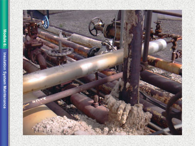
Mechanical insulation for commercial building and industrial applications is important to facility operations and manufacturing processes, yet it is often overlooked and undervalued. National standards, universal energy policies, and even generally accepted recommendations for what should be insulated, what insulation systems are acceptable for a specific use, and application best practices do not currently exist.
Development of mechanical insulation specifications and the selection of an insulation system are normally influenced by past practices or by the most knowledgeable person in the decision chain or industry segment included in the design-selection process.
Past Practices and Knowledge?
The topic of whether to depend on past practices or a knowledgeable resource produces many fundamental questions. For example, if relying on past practices, did those practices lead to a successful insulation system? Did the system perform to expectations? Were conditions like the cost of energy different 5, 10, or 20 years ago versus today? Are there new technologies or approaches that should be considered? Where can someone obtain unbiased information on what should be considered in designing, selecting, specifying, installing, and maintaining an insulation system?
If depending on a specific knowledge source, where is that source? Many—maybe most—engineering and architectural courses contain maybe 1 hour, if that, on mechanical insulation. The knowledge base in many engineering, architectural, and facility owner firms has eroded due to attrition, right sizing, and multitasking. In addition, the insulation manufacturers who for years were the educators of the industry have, for a multitude of reasons, dramatically reduced their in-person communication and education efforts.
Combine all of these factors, and you find the value of mechanical insulation is not being realized to its potential in reducing U.S. dependency on foreign energy sources, improving the environment, improving U.S. global competitiveness, and providing a safer work environment.
Mechanical insulation is applied but rarely “engineered.” With the best intentions, but not necessarily with thorough knowledge, many specifications have evolved primarily based upon modification of old documents. This practice has occurred along with a lack of mechanical insulation educational and awareness programs as to the value in having a properly engineered, installed, and maintained mechanical insulation system. This has led to the underutilization of mechanical insulation in energy conservation, emission reduction, process and productivity improvement, life-cycle cost reduction, personnel safety, and workplace improvement applications.
It is not like there are no mechanical insulation resources available. Several excellent guide specifications, handbooks, standards, and practices have been available for years. The effective use of those resources, however, is based on the premise that the user has access to them and has some level of knowledge about mechanical insulation. That assumption may not always be correct.
In response to the need for this information, the National Institute of Building Sciences (NIBS) in June 2005 formed the National Mechanical Insulation Committee (NMIC) for Building and Industrial Applications. This committee was created to bring together major governmental agencies, private industry, and organizations that are concerned with the design, installation, and maintenance of mechanical insulation systems. NIBS and NMIC offer the opportunity for a constructive public and private partnership in the examination of topics related to mechanical insulation. This committee will also provide education as to its findings regarding the value of properly engineering, applying, and maintaining mechanical insulation systems.
The National Institute of Building Sciences (NIBS), which is headquartered in Washington, D.C., was authorized by the U.S. Congress in the Housing and Community Development Act of 1974. In establishing NIBS, Congress recognized the need for an organization that could serve as an interface between government and the private sector. The institute’s public interest mission is to improve the building regulatory environment; facilitate the introduction of new and existing products and technology into the building process; and disseminate nationally recognized technical and regulatory information.
NIBS is a non-profit, non-government organization that brings together representatives of government, the professions, industry, labor, and consumer interests to focus on the identification and resolution of problems and potential problems that hamper the safe, affordable structures for housing, commerce, and industry throughout the United States. NIBS operates with a balanced blend of public and private funding and representation. This approach has enabled NIBS to bring together the nation’s finest expertise available from the public and private sectors to identify and resolve issues affecting the building process, and assure that no single interest area will dominate or hold undue influence over NIBS and its work. It also ensures both the maintenance and free exchange of information.
In early 2005, Marc LaFrance, technology development manager for the Buildings Technology Program at the Department of Energy (DOE), asked Earl Kennett, vice president of NIBS, to meet with the National Insulation Association (NIA) to explore avenues that could enhance the use of mechanical insulation in the commercial building and industrial sectors for energy conservation and the reduction of greenhouse gas emissions. That led to the development of the NMIC.
National Mechanical Insulation Committee (NMIC)
Individuals from the following government agencies and industry associations worked together in the development of the MIDG, with funding being shared between government agencies through NIBS and industry through NIA’s Foundation for Education, Training and Industry Advancement:
- American Society of Heating, Refrigerating and Air-Conditioning Engineers (ASHRAE)
- Architectural Computer Services, Inc. (ARCOM-Masterspec)
- General Services Administration (GSA)
- Midwest Insulation Contractors Association (MICA)
- National Institute of Building Sciences (NIBS)
- National Insulation Association (NIA)
- North American Insulation Manufacturers Association (NAIMA)
- Oak Ridge National Laboratory (ORNL)
- United States Army Corps of Engineers (USACE)
- United States Department of Energy (DOE)
- United States Department of Veterans Affairs (VA)
- United States Naval Facilities Engineering Command (NAVFAC)
The objective of NMIC is to identify, develop, and disseminate information related to mechanical insulation in commercial building and industrial applications by:
- examining current policies, procedures, and practices;
- identifying research or testing needs;
- developing recommendations using the best science and data available;
- providing education and awareness programs as to the merits and value of proper insulation systems;
- establishing a roadmap to implement significant improvements in design and insulation system selection; and
- establishing application best practices.
Recognizing the problems related to the lack of knowledge with mechanical insulation, the committee’s first initiative was the development of an Internet-based Mechanical Insulation Design Guide (MIDG), to be part of NIBS’ online Whole Building Design Guide (WBDG). This guide will be continually updated as deemed necessary and appropriate to reflect current and state-of-the-art information.
The committee was in agreement that the MIDG should not be another general guide specification, but instead should be a comprehensive, one-stop resource to assist the novice or the knowledgeable user in the design, selection, specification, installation, and maintenance of mechanical insulation.
Defining Mechanical Insulation
For purposes of clarity and communication, NMIC has defined the mechanical insulation market as follows: Mechanical insulation shall be defined to encompass all thermal, acoustical, and personnel safety requirements in the following categories:
- Mechanical Piping and Equipment (Hot and Cold Applications)
- Heating, Ventilating, and Air-Conditioning (HVAC) Applications
- Refrigeration and Other Low-Temperature Piping and Equipment Applications
Mechanical insulation in the commercial building sector is defined to include education, health care, institutional, retail and wholesale, office, food processing, light manufacturing, and similar applications.
Mechanical insulation in the industrial sector is defined to include power, petrochemical, chemical, pulp and paper, refining, gas processing, brewery, heavy manufacturing, and similar applications.
As its name implies, the Mechanical Insulation Design Guide (MIDG) is intended to assist mechanical engineers, architects, facility owners, designers, specifiers, and users of mechanical insulation systems in commercial building and industrial applications. The concept is that with increased unbiased knowledge of mechanical insulation, indirect and direct users of mechanical insulation will be afforded the opportunity to properly specify, select, install, and maintain quality mechanical insulation systems for initiatives related to:
- improving energy conservation;
- reducing greenhouse gas emissions;
- improving condensation control;
- minimizing the opportunity for mold growth;
- minimizing the possibility of corrosion under insulation (CUI);
- providing a safer and better working environment;
- increasing productivity with improved process control;
- enhancing sustainable design initiatives;
- improving life-cycle costs;
- providing an exceptional return on investment (ROI); and
- being better prepared to use other resources and evaluate both mechanical insulation materials and systems.
Scope of the MIDG
The scope of this design guide includes the design, specification, installation, and maintenance of mechanical insulation systems for use within the mechanical insulation markets. Specialized insulated air-handling products (flex-duct and duct board products) are not considered a part of the mechanical insulation industry from the perspective of this guide and, accordingly, are not addressed.
The MIDG is part of NIBS’ Whole Building Design Guide (WBDG) at www.wbdg.org. The WBDG is an evolving, Web-based resource intended to provide architects, engineers, facility managers, project managers, and other end users with design guidance, criteria, and technology for “whole buildings.” For the purposes of the MIDG, whole buildings encompass industrial and commercial building applications. The WBDG and MIDG will be continually updated and are structured as vertical portals, enabling users to access increasingly specific information as they navigate deeper into the site. The MIDG has been developed within the same principles as the WBDG. The WBDG and MIDG are available on a no-cost basis to all users.
Using the MIDG
The engineering design process is generally divided into the following phases:
- Identify the need or define the problem.
- Gather pertinent information.
- Identify possible solutions.
- Analyze and select a solution.
- Communicate the solution.
For an insulation design project, these phases could be restated as follows:
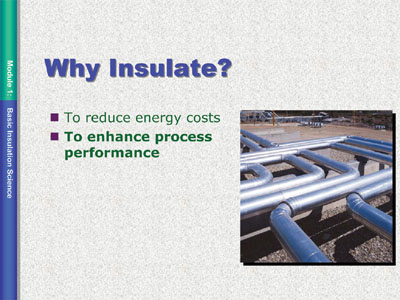
Identify the design objectives. (Why insulate?)
- Identify what is to be insulated. (What?)
- Identify the location and appropriate ambient design conditions. (Where?)
- Identify the materials and systems available. (How and with what?)
- Analyze and determine the acceptable solutions. (How much and how to?)
- Write the specification.
Overview of the MIDG
The MIDG is organized to help develop answers to these questions. The guide is divided into the following sections:
Design Objectives. This section aims to answer the questions why, what, and where. It includes a discussion of each of the potential design objectives (why?) and considerations for mechanical insulation systems (what and where?) that should be addressed when designing or selecting an insulation system. An insulation system can be designed for specific objectives, such as energy conservation or condensation control, or for multiple objectives. To select the right insulation system, a user needs to have a clear understanding of the objectives for the finished system.
Most engineers, architects, and end users are familiar with the use of insulation to reduce heating and cooling loads, and control noise in building envelopes. Insulation for pipes, ducts, tanks, and equipment are not as familiar. The installed cost of these insulation systems is usually a small part of the total cost of the project. As a result, mechanical insulation is often overlooked, undervalued, or improperly specified and maintained.
Mechanical insulation is primarily used to limit either heat gain or heat loss from surfaces operating at temperatures above or below ambient temperatures. Mechanical insulation may be used to satisfy one or more of the following design objectives:
- Condensation Control
- Energy Conservation
- Economic Considerations (Return on Investment)
- Environmental Considerations (Sustainability)
- Fire Safety
- Freeze Protection
- Personnel Protection (Safety)
- Process Control
- Noise Control
In addition to these design objectives, the following considerations may require attention when designing a mechanical insulation system:
- Abuse Resistance
- CUI
- Indoor Air Quality
- Maintainability
- Regulatory Considerations
- Service and Location
- Service Life
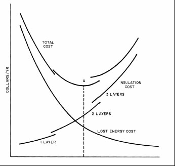
Designing insulation systems can be complicated. In some projects, multiple design objectives must be satisfied simultaneously. For example, the objective may be to provide the economic thickness of insulation and to avoid surface condensation on a chilled water line. The chilled water line may pass through various spaces within the project. Since the various spaces may have differing temperature and humidity conditions, it is likely that different insulation materials, thicknesses, and coverings may be required for a single line. Since projects may involve many lines, as well as pieces of equipment and ducts operating at various service temperatures in different environmental conditions, it is obvious that a systematic approach is required for all but the simplest applications.
Materials and Systems. This section addresses the questions of how and with what. In most cases, there are multiple types of mechanical insulation materials from which to choose for any given application. This section discusses each of the respective material categories and provides links to additional resource information and to manufacturers of the various materials.
There are a wide variety of insulation materials, facings, and accessory products available for use on mechanical systems. The list changes continually as existing products are modified, some products are phased out, and new products are developed. The task for the insulation system designer is to select the products or combination of products that will satisfy the design requirements at the lowest total cost over the life of the project. This is not easy. The designer will usually find that there are a number of products or systems that will work, and the final choice will depend on design expectations, cost, availability, or other considerations.
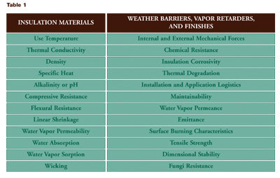
This section reviews various commonly used materials and describes important performance or physical properties for insulation materials and weather barriers, vapor retarders, and finishes associated with the various materials.
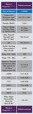
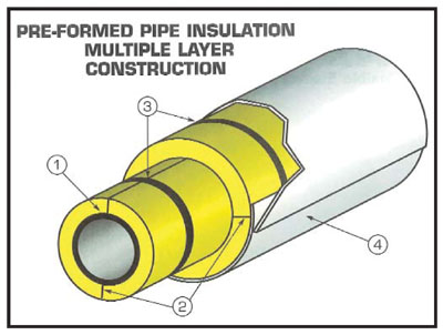
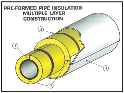
Selecting an insulation material and finish for a particular application requires an understanding of the requirements and physical properties associated with the various materials. Figure 2 shows a few of the physical requirements and properties discussed within the MIDG.
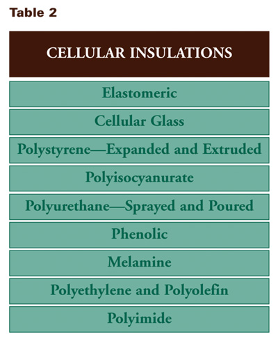
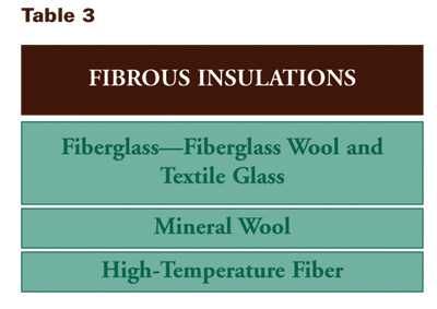
The MIDG has categorized the various mechanical insulation materials into the following major types:
- Cellular
- Fibrous
- Flake
- Granular
- Reflective
Applicable materials under each category are listed alphabetically in the MIDG.
Cellular insulations are composed of small, individual cells either interconnecting or sealed from each other to form a cellular structure. Glass, plastics, and rubber may comprise the base material, and a variety of foaming agents are used.
Cellular insulations are often further classified as either open cell (cells are interconnecting) or closed cell (cells are sealed from each other). Generally, materials that have greater than 90 percent closed-cell content are considered to be closed-cell materials.
Fibrous insulations are composed of small-diameter fibers that finely divide the air space. The fibers may be organic or inorganic, and they are normally (but not always) held together by a binder. Typical inorganic fibers include glass, rock wool, slag wool, and alumina silica.
Fibrous insulations are further classified as either wool or textile-based insulations. Textile-based insulations are composed of woven and non-woven fibers and yarns. The fibers and yarns may be organic or inorganic. These materials are sometimes supplied with coatings or as composites for specific properties, such as weather and chemical resistance, reflectivity, etc.
Flake insulations are composed of small particles or flakes that finely divide the air space. These flakes may or may not be bonded together. Vermiculite, or expanded mica, is flake insulation.
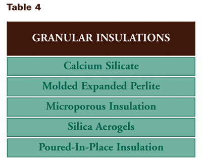
Granular insulations are composed of small nodules that contain voids or hollow spaces. These materials are sometimes considered open-cell materials since gases can be transferred between the individual spaces. Calcium silicate and molded perlite insulations are considered granular insulations.
Reflective insulations and treatments are added to surfaces to lower the long-wave emittance, reducing the radiant heat transfer to or from the surface. Some reflective insulation systems consist of multiple parallel, thin sheets or foil spaced to minimize convective heat transfer. Low-emittance jackets and facings are often used in combination with other insulation materials.
Another category of material sometimes referred to as thermal insulating coatings or paints is available for use on pipes, ducts, and tanks. These paints have not been extensively tested, and additional research is needed to verify their performance from an insulation value perspective in comparison with other categories of mechanical insulation.
Most mechanical insulation systems require a covering or finish material to protect the insulation from damage. Weather, mechanical abuse, water-vapor condensation, chemical attack, and fire are all potential sources of damage. Appearance coverings are also used to provide the desired aesthetics. Depending on the location and application, the functions performed by coverings or finish materials can include the following:
- Weather barriers. When installed on the outer surface of thermal insulation, these materials protect the insulation from weather, such as rain, snow, sleet, dew, wind, solar radiation, atmospheric contamination, and mechanical damage.
- Vapor retarders. These materials retard the passage of water vapor into the insulation.
- Mechanical abuse coverings. These materials protect the insulation from damage by personnel, machinery, etc.
- Condensate barriers. Sometimes called moisture retarders, these are normally used as an inner lining for metal weather barriers, which bar the condensate that tends to form on the inner surface of the metal jacket.
- Appearance coverings. These materials are used over insulation systems to provide the desired color or appearance.
- Hygienic coverings. These materials are used to provide a smooth, cleanable surface for use in food processing, beverage, or pharmaceutical facilities.
These functions are performed by a number of different materials or material systems. In many cases, a single material can provide multiple functions. (For example, a metallic jacketing often serves as protection from both the weather and mechanical abuse.) There is some inconsistency and confusion in the nomenclature used for these materials. The MIDG discusses these topics and provides the user with some clarity on the various topics.
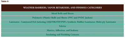
The MIDG has categorized the various weather barriers, vapor retarders, and finishes into six major types or categories (see Figure 6).
The Materials and Systems section of the MIDG also includes a discussion of insulation fabrication standards, and removable and reusable insulation covers. In addition, it includes information on an array of accessory materials that are part of the total insulation system.
MIDG Linkage to NIA’s Online MTL Product Catalog
The MIDG provides immediate linkage to specific material data, including submittal sheets, and further linkage to insulation manufacturers. This is a one-stop, online shop for manufacturers’ technical literature about specific product offerings. This direct linkage saves time in obtaining manufacturer information for specific insulation materials versus having to individually search a host of websites.
The MTL Product Catalog is the only online library of technical information for the insulation industry. It is a searchable database that allows users to find products from participating manufacturers easily and quickly on a 24-7 basis. It is the most convenient, flexible, efficient, and cost-effective way to find the most current information.
This service is provided to NIBS and the MIDG by the NIA through direct access to the association’s MTL Product Catalog. The MTL Product Catalog is continually up-dated by participating manufacturers and fabricators, providing MIDG users with current and timely information.
Installation of Mechanical Insulation
Installation of mechanical insulation is typically managed by experienced contractors who specialize in the mechanical insulation sector of the commercial, industrial, and HVAC sectors of the construction industry. As with similar construction-related activities, the project can be successful or not, depending on the design, materials selected, and—most importantly—the quality of the installation. Using an experienced and proven contractor is vital to the success of any mechanical insulation project. The lowest installation proposal may not be the best.
The insulation contractor should be familiar with the objectives of the project and be prepared to highlight and resolve any inconsistencies or errors in the specification. Often, specific insulation or accessory products are specified, and the insulation contractor must thoroughly understand the requirements for installing these products. Code compliance is generally the responsibility of the design professional, but a knowledgeable insulation contractor should understand the code requirements in his or her location and be able to help expedite resolution of compliance issues. Sometimes there are conflicts between the specifications, the manufacturers’ recommendations, and the code. Early identification and resolution of these conflicts is desirable.
The MIDG provides installation information related to the following:
- Pre-Work Considerations
- Finishes
- Securing Methods
- Pipe and Tubing
- Insulation Pipe Hangers
- Tanks, Vessels, and Equipment
- Ducts
- Special Considerations
- Inspection and Maintenance
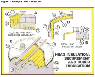
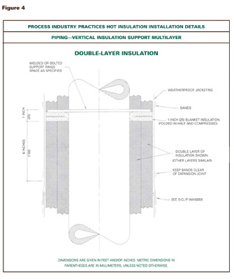
Within the Installation section of the MIDG, there are direct links to both Midwest Insulation Contractors Association (MICA) and Process Industry Practices (PIP) resources that provide valuable installation details and schematics.
Design Data
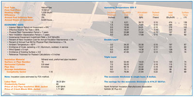
This section of the MIDG is a collection of information that is useful to designers and end users of mechanical insulation systems. The section contains some simple calculators that allow the calculation of heat flow and surface temperatures. Discussion of and links to more sophisticated computer programs for performing these calculations are also included. This section contains information on:
- estimating heat loss and heat gain;
- controlling surface temperature;
- determining dimensions of standard pipe and tubing insulation; and
- estimating heat loss from bare pipe and tubing.
Online MIDG calculators include the following:
- Calculator that estimates time to freezing fluid in an insulated pipe. This calculation estimates the time for a fluid-filled pipe (no flow) to reach a freezing temperature.
- Temperature drop calculator. This tool calculates temperature drop of a fluid flowing in a duct or pipe.
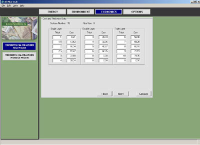
- Simple thickness calculator. This calculator estimates the thickness of insulation required to obtain a specified surface temperature given the boundary temperatures, the conductivity of the insulation material, and the surface coefficient.
- Simple heat-flow calculator. This calculator estimates heat flow through an insulation for flat and cylindrical systems given the temperature on each side and the effective conductivity of the insulation material.
Resources
This section of the MIDG contains an extensive list and linkage to the following resources:
- Relevant Mechanical Insulation Standards and Guide Specifications
- American Society of Heating, Refrigerating and Air-Conditioning Engineers (ASHRAE)
- Architectural Computer Services, Inc. (ARCOM-Masterspec)
- American Society for Testing and Materials (ASTM) International
- Midwest Insulation Contractors Association (MICA)
- National Association of Corrosion Engineers (NACE)
- National Fire Protection Association (NFPA)
- Process Industry Practices (PIP)
- Underwriters Laboratories (UL)
- U.S. Government Agency Guide Specifications
- Numerous References and Other Resources
- Case Studies
- Educational Resources
- National Insulation Association
- National Insulation Training Program (NITP)
- Insulation Energy Appraisal Program (IEAP)
- 3E Plus® Insulation Software Training
- Awareness Presentations (Audience Tailored)
- Insulation Science Glossary
- American Society of Heating, Refrigerating and Air-Conditioning Engineers (ASHRAE) Learning Institute
- Professional Development Course: Mechanical Insulation Training
MIDG Is Making It Happen
The Mechanical Insulation Design Guide (MIDG) is the most extensive single online resource for mechanical insulation systems developed to date. It will be continually updated and, as such, will be a “living” document. It is intended to be a comprehensive, unbiased educational database and vertical portal resource to assist all specifiers and users of mechanical insulation systems in the design, specification development, system selection, installation, and maintenance of mechanical insulation systems.
Insulation gets very little respect and is often taken for granted. When designed, applied, and maintained properly, insulation is a powerful technology—one that provides long-lasting benefits. However, insulation is often overlooked or relegated to the bottom of the list and ignored. One reason may be that insulation systems have no moving parts, no bells and whistles, no computer chips, and no fancy gauges. This technology is not some mysterious myth. The principles of insulation are simple and not necessarily revolutionary—possibly another reason why it is often overlooked.
However, the bottom line is that insulation can often provide an annual return on investment (ROI) of greater than 100 percent. With energy efficiency and conservation, reduction of greenhouse gas emissions, sustainable design, safety, condensation control, mold prevention, the indoor working environment, and a host of other initiatives being priorities in today’s world, maybe it is time to begin thinking about this underutilized, undervalued, and underappreciated technology differently.
To take full advantage of this forgotten and powerful technology, it is essential to begin thinking about the value insulation can provide. Mechanical insulation is a resource that, when all of the benefits are considered, should prompt the question, “Why hasn’t this been thought of before?”
The MIDG provides users with a single platform for increasing their knowledge of mechanical insulation in an efficient, easy-to-understand, cost-effective manner. That’s not a bad formula for a technology that can provide an unrivaled ROI opportunity in the new construction and maintenance arenas. Insulation accomplishes all of this while helping reduce U.S. dependency on foreign energy sources, improving the environment, and improving the economy.
The official URL for the MIDG is www.wbdg.org/midg. To learn more about NIA’s MTL Product Catalog, please visit www.insulation.org/mtl. For more information on the Whole Building Design Guide, please visit www.wbdg.org.
Acknowledgements
Without the commitment of the National Institute of Building Sciences (NIBS) and the National Insulation Association (NIA), the MIDG would not have been possible. The support and active participation of the National Mechanical Insulation Committee (NMIC) members, made up of a long list of contributing organizations, manufacturers, fabricators, and contractors, has made the MIDG a quality educational resource. Special appreciation is extended to Christopher P. Crall, whose knowledge of mechanical engineering and thermal insulation has been invaluable in the development of the MIDG.