Category Archives: Global

Although people most often think of insulation in terms of its applications in buildings, it plays a role in preserving the integrity and efficient function of other types of structures as well. This article focuses on one such structure—the new Woodrow Wilson Bridge in the Washington, D.C., area—and how insulation plays a role in its future success. It also serves as a case study, because as the nation’s infrastructure ages and traffic volumes increase, many of the concerns here are applicable to structures throughout the United States. This article provides background on the original bridge and the recent project to replace it.

The Need for a Bridge

Road transportation in the metropolitan Washington, D.C., area is not merely an “inside-the-beltway” concern. While it is true that commuters from Virginia, Maryland, and the District of Columbia move back and forth between jurisdictions during their work days, as the nation’s capital and a key point on Interstate I-95, the area also supports personal and business travel in the mid-Atlantic region. This travel is complicated by the existence of the Potomac River, which separates Virginia from Maryland and the District.

In the mid-1950s, Congress approved construction of what was originally known as the Jones Point Bridge to connect Alexandria, Virginia, and Oxon Hill, Maryland. When the bridge opened in December 1961, it consisted of six lanes—three in each direction—to serve an anticipated daily traffic volume of 75,000 vehicles. To accommodate river traffic, the 6,000-foot-long, multispan, girder design included a bascule drawbridge located approximately 500 feet east of the Virginia shoreline. It is one of just nine movable-span bridges in the U.S. interstate system.

The bridge provided the first direct connection across the Potomac River for Washington, D.C., suburbs in Virginia and Maryland. At the time, it was neither anticipated nor designed to be the busy commuter route and East Coast interstate travelway into which it eventually evolved.

Outgrown Nearly Immediately

Unfortunately, the bridge reached its design volume in just 8 years. Today, traffic volume is three times the original estimate, resulting in about 7 hours’ worth of backed-up traffic that frequently runs several miles in either direction. It is not just local-area commuters who suffer from this congestion. Consider that in 1993 $58 billion in trucked gross national product (GNP) —at least 1.3 percent of total—passed over the bridge. Today, some 11 percent of the daily traffic is large trucks.

To make matters worse, the narrow shoulders provided in the original design, coupled with the increased traffic, led to a disproportionately high accident rate. Although the bridge was widened to accommodate 7-foot-wide emergency shoulders on each side when it was re-decked in 1983, its accident rate is still nearly twice that of similar stretches of highway in Virginia and Maryland, and of the Washington, D.C., beltway’s other main bridge, the American Legion Bridge. As the highway leading to the bridge was widened to eight lanes, the decrease to six lanes on the bridge created a bottleneck and more congestion.

Excessive Volume Stresses the Structure

All of that excess traffic (and weight) took its toll. In 1994, Hardesty and Hanover, a New York engineering firm, issued a report summarizing the results of a publicly funded study conducted by 12 bridge engineers, including representatives from the Federal Highway Administration, the District of Columbia, Maryland, and Virginia. The report warned that the higher-than-expected volume of traffic (including large numbers of trucks with maximum legal loads higher than those permitted on highways back when the original bridge was designed) was causing excessive vibrations that were damaging the bridge supports.

The bottom line: Without major upgrades to the structure, the bridge would need to be closed to truck traffic by 2004. Given the cost to upgrade, the traffic disruption it would cause, and the fact that the rehab would not result in more lanes of traffic, the bridge suffered from such extreme wear and tear that it needed to be replaced just 40 years after it was unveiled.

The Search for a Solution

In 1988, the federal government, along with the District of Columbia, Maryland, and Virginia, initiated a study aimed at replacement solutions for the decaying and outgrown bridge. With so many jurisdictions—and local public opinion—involved, the project planning process grew, with panel studies conducted into the mid-1990s. The options under consideration included a tunnel, a new drawbridge, and a fixed, high-level bridge. The tunnel represented the costliest of the alternatives considered. And residents of nearby Old Town Alexandria raised concerns about the imposing appearance of a new, high-span bridge, whose steeper grades might have posed a challenge for trucks to run at normal speeds (possibly slowing bridge traffic more).

In the end, the solution chosen was a $2.43-billion project encompassing a 7.5-mile stretch including roadways and interchanges in both Maryland and Virginia, as well as a new bridge. The new bridge, which represents $826.1 million of the total project cost, is a twin-span drawbridge that is 20 feet higher than the old. The 70-foot vertical navigation clearance over the river will decrease the number of bridge openings (and resulting roadway traffic interruptions) from 260 down to 65 per year (about 1 per week), a 75-percent reduction.

In addition, the new bridge will accommodate 12 lanes of traffic, which breaks down as follows:

  • Eight general-purpose driving lanes
  • Two lanes for merging and diverging traffic
  • One express and local lane
  • One lane set aside for future rail and transit lines (which will open once the connecting systems are established on both sides of the river)
Roles for Insulation

Insulation plays an important role in optimizing performance and longevity of the new bridge. During the construction phase, insulation was critical in ensuring the structural integrity of the new bridge by controlling the temperature of the concrete as it set. In some areas of the bridge (the deck surface, for example), insulation was required to keep the concrete warm as it set, protecting it from the cold of the outside environment. In other areas—surrounding the forms for the massive concrete shapes of the foundation for the draw span—insulation was used to prevent the formation of cracks caused by thermal shrinkage. In the latter case, insulation essentially protected the concrete from itself.

In a recent interview discussing the role of insulation in the Wilson Bridge Project, Construction Manager Jim Ruddell, P.E., vice president at Parson Brinckerhoff Construction Services, began by focusing on the basic ingredients (sand, cement, water, and rock), likening the process to baking a cake. Different types of applications, much like different types of cake (think chocolate torte versus cheesecake, for example) require different ingredients. Professionals in the construction industry are familiar with how the chemical reaction from mixing the ingredients of concrete generates heat. For the new bridge, consideration was given to designing a mixture that would meet requirements for strength and chloride permeability. With co-author Paul Gudelski, Rudell described the results of heat-flow analysis of the mass concrete mix in “A Capital Bridge” (Concrete Engineering International, Autumn 2004) as follows:

The mix replaced 75 percent of the Portland cement with ground granulated blast furnace slag (ggbs), and included air entraining and high-range water reducing agents to enhance freeze-thaw resistance, workability, and provide minimum 56-day strength of 27.6 megapascals (MPa).

In addition to the need to design the best possible concrete mix to begin with, a project such as this presents issues and considerations related to the structure’s unique shape and size. Ruddell described the challenges of working with the large, geometric shapes used in different sections of the bridge. (To give an idea of the extremities of scale, the four blocks representing the foundation for the drawbridge used 6,400 yards of concrete and measured 89 x 119 x 16 feet.) In the Wilson Bridge Project, custom-fabricated forms for the large concrete structures were treated with spray-on isocyanate foam insulation in an effort to keep the temperature toward the exterior of the structure as consistent as possible with that at the core. According to Ruddell, the goal was to maintain a differential no greater than 35 degrees between the core and the outside. Along with the insulation, cooling pipes were used to circulate water within and cool the core as needed. Thermocouples embedded in the concrete regulated temperature.

For large concrete structures, the main environmental factor was ambient temperature. By preventing the concrete faces from cooling too quickly, the foam insulation, in part, allowed work to take place regardless of season. For the smaller structures (those smaller than 6 x 6 x 6 feet) and for the bridge deck, the primary environmental challenge came from the wind. For these sections, insulation was used to protect against freezing, as the concrete was kept covered.

For the elevated slabs of the bridge deck, an insulating blanket system was employed to keep the concrete from freezing, as shown in Photos 1 and 2. The bottom of the blanket is reflective metal, designed to reflect and conduct heat down and out throughout the covered structure (in this case, the deck). In addition to the blankets themselves, the system included heating tubes that circulated hot fluid under the blankets. Although the blankets are full of air bubbles, they are durable enough to allow workmen to walk on them.

Interestingly, the Potomac River was used to insulate one area of the bridge as it was constructed. One of the first steps in the bridge-construction process was construction of temporary watertight structures called cofferdams, where the bridge pilings were built. Once the cofferdams were ready, water was pumped out to create a dry environment. The river water just outside the cofferdams actually created a stable environment, from a temperature standpoint.

Ruddell says the most difficult of the structures were the so-called knuckle pieces: the blocks of concrete at the top of the V-piers. The sections are full of reinforcing steel, post-tensioning bars, “a whole bunch of stuff … that we need structurally,” says Ruddell. The concrete job was already compounded by the existence of so many critical elements in one place, but then there was the shape, which extends out from the foundations to form an upside-down triangle. The end pieces at the top were especially vulnerable to temperature differential. These factors represented something of a “perfect storm” of challenges. Because the knuckles carry so much load, quality and structural integrity of these sections was critical. According to Ruddell, the knuckles took about 1 month to construct, were cast in 1 day, and then took another month for thermal monitoring.

Concrete—the attention to developing the perfect blend and using insulation to protect it when setting—is just one area where designers and engineers looked for innovative ways to extend the new bridge’s life span. Gudelski and Ruddell describe how more-durable materials will extend the life of the new draw span decks here:

… the new draw span decks are designed with stainless steel (Unified Numbering System designation S31803 or S31653) reinforcing and lightweight (1,890 kilograms per cubed meter), and chloride-resistant (less than 2,000 coulombs) concrete with design strength of 31.0 MPa.

In key areas such as the V-piers’ post-tensioning ducts, high-performance thixotropic grout is used instead of conventional grout. Thixotropic grout pulls water, substantially reduces segregation, and serves as a barrier to protect against corrosion.

Conclusion

The Wilson Bridge Project can serve as both a “lesson-learned” warning and a case study for improving the nation’s infrastructure. The federal government and local jurisdictions will not be able to afford replacing substantial interstate infrastructure elements every 40 years. Along with studying the demographics that will drive use and demand, planners need to work with engineers and designers to use the best technology from all systems—not just insulation—to optimize performance and longevity in the finished product.

  1. Woodrow Wilson Bridge Project, www.wilsonbridge.com
Figure 1

The insulation industry has undergone profound changes over the past 50 years. Increasing energy conservation needs and evolving technologies have required major advances in insulation materials, application, and cost-efficient systems for end users. Industry advancements have included new jacketing materials that have self-sealing laps, improvements in vapor-retarder materials, removable and reusable insulation covers, and increased material thickness to provide greater energy savings and return on investment. Specifications calling for lower-perm products, as well as safety and closure procedures in installation, are tangible evidence of how the industry has responded to challenges like corrosion under insulation (CUI). Here is a brief review of CUI, with a discussion of some ways to address it.

Maintenance engineers and coordinators, process and project engineers, and operation managers continue to grapple with the problem of CUI, one of the most expensive facility-related problems facing industry today. Recent studies suggest that CUI costs industry millions of dollars annually, and CUI problems account for more unexpected facility downtime than all other causes combined. The increase in corrosion failures under thermal insulation makes CUI a particular concern for petroleum, chemical, food-processing, and other types of industrial operations.

CUI is caused by the ingress of water into insulation, which then traps the water like a sponge, keeping it in direct contact with the metal surface. The source can be rainwater, leakage, deluge-systems water, wash water, or sweating from temperature cycling or low-temperature operation, as in refrigeration units. It also occurs because of the availability of oxygen trapped in the insulation. As temperatures increase, moisture cannot escape. Chlorides and ions in insulation also greatly promote corrosion.

Without a 100-percent vapor seal, moisture seeps in, causing cracking and subsequent corrosion. With metal jacketing, caulking is required to seal the joints. When temperatures change, materials expand and contract, causing cracks in the caulking and allowing moisture to permeate. Similarly, materials without zero permeability, such as mastic, can crack. This also allows moisture into the insulation system.

The American Petroleum Institute (API) code 570, “Inspection, Repair, Alteration, and Rerating of In-service Piping Systems” (the piping code first published in 1993), identifies CUI as a special concern. This code is one of the industry standards, along with NACE’s RP098-98, and the OSHA 1910 rule demands that organizations maintain a program to meet the standard.

Hidden Problems

CUI is often difficult to detect because the insulation cover can mask the problem until it is too late. It is expensive to remove the insulation, especially if asbestos is involved. Various methods are used today to inspect for CUI, including radiography, ultrasonic spot reading, and X-ray. New diagnostic technologies—online, real-time corrosion monitoring systems, and others—are rapidly reaching the market. Clearly, however, prevention is still the most cost-effective approach to controlling CUI.

The problem is pervasive because most installations involve a host of environmental factors. Once water ingress occurs, there’s no stopping corrosion. Since many facility or maintenance managers cannot continuously monitor the roof, piping, or ductwork, the problem eventually makes itself known. Then costly, disruptive repair is required.

Methods of Sealing Insulation

There are many methods of sealing insulation to prevent outside water from seeping through the insulation material. Vapor-barrier mastics can be used for this purpose. Applied by spray, brush, or roller, these come in a variety of colors and are applied in several layers. Using metal jacketing—both stainless steel and aluminum—in various thicknesses is the most common method of protecting insulation materials. This is now provided with inner linings that offer tremendous chemical resistance. Once the metal jacketing is applied, the seams are often caulked with a silicone or other type of sealant to prevent the ingress of water through the lap. Other new jacketing products that provide extremely low perm ratings include polyvinylidene chloride resins, which lock out
oxygen and moisture, frequently used on urethane, Styrofoam, and foam glass because of their excellent vapor-barrier properties.

Materials used to circumvent CUI must be capable of withstanding thermal cycling and continuous exposure to elevated temperatures. They must also be resistant to ultraviolet (UV) rays. If a coating is not UV resistant, it will begin to degrade, and its effectiveness will be reduced, eventually causing failure.

New Facing Materials

Installing insulation is difficult, time-consuming, and labor intensive. Typically, insulation will have to be replaced two to three times during the lifetime of a plant, at high cost and with significant disruption. While no product can guarantee total CUI prevention, new zero-permeability facing materials are gaining increased acceptance by engineers and installers. And some contractors are now adding these insulation jacketing systems to project specifications because they believe that they can deliver a quality, cost-effective solution.

The all-purpose insulation jacketing systems designed for sealing insulation over ductwork in harsher environments offer 100-percent self-adhesive overlap and bonding capabilities, and provide complete coverage over insulation. The material is weather resistant and tough, but it is easier to install. Pressure-sensitive jacketing requires no additional rivets, strapping, sealants, or off-site fabrication. And when it is installed properly, the chance of moisture getting in is low.

Reducing cost by eliminating or mitigating corrosion damage and failures while also increasing run time and productivity are goals on which everyone can agree. The perfect water-tight system remains the ultimate goal of engineers, specifiers, and owners. And with innovative products like zero-permeability, pressure-sensitive jacketing systems, they are one step closer to solving the CUI dilemma.

Refrigeration systems cover a broad spectrum of application temperatures and environments, many of which are discussed in the 2006 ASHRAE Handbook–Refrigeration. But they all face the same issues relating to both condensation control and moisture. Since moisture is a good thermal conductor, its presence in an insulation system is highly detrimental. Unlike hot systems, where marginal insulation may result in increased energy use (and added cost), refrigeration systems face condensation, which often leads to complete system failure. Even with today’s high energy costs, the design thickness in most refrigeration applications is dictated by what is needed to prevent condensation, rather than by economic payback.

Refrigeration systems typically operate in the range of 20°F (for Freon systems) to as low as -50°F (for ammonia systems). They can use a variety of refrigerants and fluids in addition to Freon and ammonia, including glycol, brine, and other specialty fluids. Copper, iron, stainless steel, or other piping materials may be used to carry the cooling medium. Typical applications include those in supermarkets; beverage-dispensing lines; chillers; and food processing, freezing, and storage facilities (for example, meat processing and dairy, vegetable, and frozen-dinner cases). Other applications include those at ice rinks and morgues, as well as various unique applications. All of these applications share common concerns regarding condensation control and long-term reliability, but they also have particular issues with installation, required thickness, and the environmental conditions in which they operate. Guidelines for insulation selection, thickness, installation, and maintenance are found in the 2006 ASHRAE Handbook–Refrigeration in Chapter 33, “Insulation Systems for Refrigeration Piping.”

Reliability should be the primary concern when considering the design and installation for any application. Design must consider factors including the application temperature, environmental considerations, consequences if a failure occurs, and expectations of the job by the owners (longevity of the system, aesthetics, etc.). Installation considerations include environmental conditions during installation, time frame allotted to complete the job, and worker training.

Below-ambient refrigerant lines are installed primarily to accomplish the following:

  • Minimize heat gain to the internal fluids
  • Control surface condensation
  • Prevent ice accumulation

Operation is generally continuous, so the vapor drive is unidirectional. Water vapor that condenses on the pipe surface or in the insulation remains there. The vapor retarder must be continuous and effective 100 percent of the time to limit the amount of vapor entering the system. The following are some important features of the insulation in various refrigeration applications:

  • Thermal conductivity, or k-value
  • Water vapor transmission (WVT) properties
  • Water absorption properties
  • Coefficient of thermal expansion
  • Moisture wicking
  • Fire and smoke performance to meet building codes

The ASHRAE handbook recommends the following insulation materials for refrigeration applications: cellular glass, closed-cell phenolic, flexible elastomeric, polyisocyurante, and polystyrene. All of these materials have one property in common: all are closed-cell foam materials, which means they will have good WVT and low water absorption characteristics.

In all cases, the entire system (seams, butt joints, and termination points) must be completely sealed with adhesives to protect against air intrusion into the system, which would carry moisture and result in condensation between the cold pipe and the insulation. Relying on a single, concentrated vapor retarder is not recommended. Generally, closed-cell foam insulations are used for these applications. Seams should be minimized. On multilayer systems, the seams should be staggered. Taped seams are only allowed as a complimentary closure system.

Supermarkets are one of the biggest and most noticeable applications for refrigeration systems. They face several issues, including changes in refrigerant, colder line temperatures, higher temperature hot gas defrost cycles, changing store designs, and pressures to reduce installation time to decrease store build time. Chapter 16 in the ASHRAE handbook, titled “Retail Food Store Refrigeration and Equipment,” details many of the issues related to this market segment. Mandated changes in refrigerants are resulting in colder line temperatures, which require increased insulation thickness to prevent condensation.

In typical conditions, a 1-inch thickness is the standard; however, in some cases where humidity is high (over 80 percent), a 1½-inch thickness may be used. (See “Insulation Thickness Versus Design Relative Humidity.”) Availability of 1½-inch wall elastomeric insulation that has a 25/50 rating when tested according to ASTM E 84 is a new development on the market. This eliminates the need for sleeving materials to obtain the 1½-inch thickness.

Hot gas defrost cycles require insulation products to withstand spike temperatures up to 250°F. Open-ceiling store designs are mandating a change from the standard black insulation to a white product for better paint coverage and appearance. The installation procedures used on supermarket applications require that copper pipe (20-foot sections) be insulated on the floor and then taken to the ceiling and hung. To expedite this process and eliminate seams, many installers have gone to 18-foot coils of insulation that can be easily slid onto the 20-foot copper lengths. The reduction in seams saves time and improves the reliability of the job.

Using preinsulated pipe hangers is a concept that is gaining acceptance in supermarkets because it saves time and improves reliability by reducing condensation at hanger locations. The majority of piping on a supermarket is indoors, but for the outdoor and rooftop sections, the use of flexible jacketing-polyvinyl chloride (PVC), AL laminates, etc., is being evaluated, either installed at the job site or factory applied to improve the longevity and appearance of the job. Use of protective coatings that need periodic maintenance is becoming less specified.

Refrigeration piping on most supermarkets is found inside, but some stores are designed with 90 percent of the piping on the roof. Some elastomeric insulation products are being promoted as ultraviolet (UV) resistant and acceptable for use outdoors without the additional protection of coatings, jackets, or cladding materials. But UV protection is not the only issue when it comes to outdoor applications. Mechanical abuse (by birds, cats, people, etc.) and environmental abuse (by hail, sand, dirt, wind, rain, etc.) play a role in the reliability and longevity of the insulation system. For optimum performance, coatings, jacketing, or cladding should be used for outdoor applications.

The insulation system installed on a supermarket refrigeration system must be highly reliable, as it will operate 24 hours a day for up to 10 years. System failure may result in a large loss of perishable foods. Closed-cell elastomeric materials have been used in this application for many years because they are extremely reliable and cost-effective. It is a primary product used for supermarket refrigeration applications because of its low WVT, allowable use temperature range, and ease of installation.

Another rather unique, behind-the-scenes refrigeration application is in beverage-dispensing units for large stadiums or coliseums, where satellite food court areas are all supplied from a central unit. In this case, multiple lines are bundled together and insulated with a single large-inner-diameter insulation coil. This keeps all the lines together and saves materials, space, and installation time. The coils are produced in long lengths to reduce seams, which also saves time and improves system reliability. Closed-cell flexible insulation materials are preferred for this application because of their flexibility during installation.

Chillers come in various sizes and models. All require insulation of the piping and chiller barrels. As with other refrigeration applications, use of new refrigerants and space constraints have caused concerns. In addition, many manufacturers have changed manufacturing locations, which means units are being shipped farther or stored longer prior to shipment. This increases the units’ exposure to weather and the resulting challenges. Plus, end users demand not only performance, but also the acceptable appearance of the delivered unit. As a result, manufacturers are moving toward insulation with preapplied UV weather and abuse protection, such as coatings or claddings that offer both performance and appearance benefits. Indoor safety and health issues at the manufacturing location may not allow the use of solvent-based adhesives, so manufacturers are using products with preapplied adhesive on either the sheet or tubular insulation. Facing increased labor costs, inventory constraints, and space limitations, some find purchasing ready-to-use kits supplied by fabricators a cost-effective option.

Using a coating or flexible jacketing can improve the appearance, durability, weather resistance, and longevity of the insulation on a unit. Flexible, closed-cell elastomeric insulation is the predominate product used in this application. A 3/4-inch thickness is commonly used.

Food processing, freezing, storage, and distribution applications often use ammonia refrigeration because of its lower operating costs. System practices for ammonia and carbon dioxide refrigerants are outlined in Chapter 3 of the ASHRAE handbook. Processed, precooked, and prepared foods all come under the regulations of the Food and Drug Administration (FDA) 21 Code of Federal Regulations (CFR), and facilities using meat products come under the regulations of the United States Department of Agriculture (USDA).

As ammonia systems are designed for smaller applications at an economical up-front cost, they are getting more consideration than more expensive operating systems. While most areas do not exceed high temperatures above 160°F, some sections may cycle from -40°F to 250°F. Lower temperatures (down to -60°F) mean greater insulation thickness (2 to 3 inches) is usually required to prevent condensation. Typically, 3 inches of insulation is used to prevent condensation, as many of these applications are in high-humidity areas. Ammonia refrigeration applications are demanding, and performance and longevity expectations are high. The majority of the insulation is installed outdoors, so jacketing selection is critical. As a result of the cost and thickness required, polystyrene and polyisocyurante with a stainless steel jacket are the most common materials used. Of key concern is corrosion of iron pipe. Moisture resistance and control of the insulation material is critical. Proper insulation installation (with no open or through seams) is a major concern, and use of secondary vapor-retarder systems is the norm. New materials that can save on material or installation costs are always being evaluated, but long-term reliability is of prime importance because downtime and iron-pipe replacement is more costly than the dollars saved up front on installation.

The refrigeration market covers a broad spectrum of applications, each with unique requirements but all with a common goal: prevention of moisture intrusion and condensation to maintain long-term system reliability. Installation techniques are just as critical as material selection. The consequences of system failure can include degraded thermal performance of the insulation, higher system operating cost, inadequate cooling capacity, mold and mildew, ice formation, ruined ceilings, slippery floors, equipment downtime, and corroded pipes.

In below-ambient systems like refrigeration applications (including chilled water and cryogenic systems), closed-cell insulation products are preferred because of their low WVT and inherent moisture resistance. It’s important to select the right insulation product for the application. Customer expectations must be matched to product performance and cost. Refrigeration applications are demanding and require careful consideration in material selection and installation to obtain optimum performance for the end user.

Figure 1

Insulation Thickness Versus Design Relative Humidity

This issue of Insulation Outlook is focusing on corrosion under insulation (please feel free to check the front cover to see if I should have stopped to ask for directions). Fortunately, corrosion only occurs under insulation once every 3 or 4 years, because it can be a considerable threat to structural integrity. I just happen to be a corrosion engineer. (And that merely acknowledges the sequence of chance events that brought this about—relatively few of my colleagues always dreamed of being corrosion engineers. I wonder how many of you, when you were a 5-year-old future firefighter or cowboy, would have punctuated career day at school with, “Insulation is where it’s at!”)

I’m also a longtime member of The National Association of Corrosion Engineers (NACE) International—The Corrosion Society, and have contributed more or less monthly columns to the society’s principal periodical for more than 5 years now. That is, until I tested positive for steroids. (I never knowingly took steroids—honestly, I thought it was morphine—though I have experienced some conspicuous muscular development that has unexpectedly improved my competitive eyebrow-raising skills).

This would seem an appropriate time to mention that nothing contained in this article should be construed as an official statement on behalf of NACE, NIA, my company, or your company—I’m not even sure I’m speaking for myself.

It is noteworthy that NACE’s technical committees are readopting Publication 10A392, “Effectiveness of Cathodic Protection on Thermally Insulated Underground Metallic Structures.” It is not necessarily a coincidence that this roughly corresponds to the
25th anniversary of the most significant advance in the prevailing approach to corrosion control for these structures: the use of barrier coatings on structure surfaces prior to the placement of insulation.

Paraphrased in a nutshell (how fitting), here are the four
general approaches to corrosion control:

    • Material selection—especially the use of components that resist corrosion in specific environments
    • Inhibitors that reduce the corrosiveness of the environment, typically inside a tank or piping system
    • Coatings and linings, typically with dielectric properties intended to isolate surfaces from corrosive environments
    • Cathodic protection (CP)

CP has been variously defined, but one view is that metal loss (the main reason for all the fuss about corrosion) happens when current leaves a buried or submerged surface at anodic sites in the form of electrically charged metal ions; CP attempts to minimize this discharge by applying an external current to the entire structure surface. This makes all sites cathodic. Reduced current discharge means reduced corrosion.

Once Upon a Time

Once upon a time (before some of today’s best practices were in common use), in the magical land of the northern Midwest, there was a direct-buried steam-piping system with fiberglass thermal insulation in half shells and a thin outer moisture barrier of galvanized steel—hardly the best choice for direct burial. The real problem, though, was underestimating the effectiveness of the insulation in preventing heat loss to the environment, which might have avoided winter soil stresses. Instead, the ground froze (and expanded), the outer shell was crushed, and the spring thaw brought oxygenated water into contact with the pipe steel at joints and voids.

An external CP system had been installed, but current distribution is essentially linear. And CP current actually promotes moisture migration. When the water migrated along under the insulation, adequate protective current could not reach all of the corroding sites. The same conditions limited the ability to identify active corrosion with traditional test methods for CP evaluation. The resulting failures were basically consistent with the fundamental conclusion of 10A392: “Generally, the application of external CP to thermally insulated metallic surfaces has been ineffective.”

Surface coatings are much more successful in conjunction with a nonmetallic external jacket as a moisture barrier. The established developments in coatings and linings, material selection, and construction practices, along with evaluation techniques like internal pipeline inspection tools, make it possible to use the advantages of thermal insulation for underground metallic structures. And that greatly reduces the risk of corrosion failures, so we can all live happily ever after.

Corrosion under insulation (CUI) is a well-understood problem, and mitigation methods are well established. However, it is pervasive and continues to cost the process industry many millions of dollars annually. In 2002 a large chemical company spent over $5 million dollars replacing 304 stainless steel equipment because of chloride stress corrosion cracking (CSCC) under insulation.1  The cost of the downtime due to the loss of production was even more significant. In another example, one petrochemical company estimates that CUI accounts for as high as 40 to 60 percent of the company’s piping maintenance costs.2  Similar case histories are commonplace within the process industries. An effective CUI prevention strategy based on life-cycle costs can significantly reduce costs due to downtime, maintenance repair, and inspection. The corrosion of carbon steel under wet insulation is nonuniform general corrosion and/or highly localized pitting. In austenitic stainless steels, the main forms of corrosion are pitting and stress corrosion cracking caused by chlorides.

Corrosion of Steel Under Insulation Mechanism

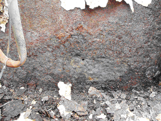
Figure 1 shows a section of a large carbon-steel storage that has undergone corrosion in a localized region leading to a through-wall hole. The corrosion occurred on the sidewall near the tank bottom where the coating failed, exposing the carbon steel to wet corrosive conditions under the insulation. Carbon steel does not corrode simply because it is covered with insulation, but because it is contacted by aerated water. In a corroded system, insulation can provide an annular space or crevice for the retention of water with full access to oxygen (air) and other corrosive media. If not careful, the insulation can provide a material that may wick or absorb and may contribute contaminants that increase or accelerate the corrosion rate. The corrosion rate of carbon steel is principally controlled by the temperature of the steel surface, availability of oxygen and water, and the presence of corrosive contaminant species in the water.

Water sources. There are two primary water sources involved in CUI of carbon steel. First, breaks in the weatherproofing can lead to infiltration of water to the metal surface from external sources such as rainfall, drift from cooling towers, condensate falling from cold service equipment, steam discharge, process liquid spillage, spray from fire sprinklers, deluge systems, washrooms, and from condensation on cold surfaces after vapor-barrier damage. Second, a major corrosion problem develops in situations where there are cycling temperatures that vary from below the dew point to above-ambient temperatures. In this case, the classic wet/dry cycle occurs when the cold metal develops water condensation that is then baked off during the hot/dry cycle. The transition from cold/wet to hot/dry includes an interim period of damp/warm conditions with attendant high corrosion rates.

Contaminants. Chlorides and sulfates are the principal contaminants found under insulation. These may be leached from the insulation materials or from external waterborne or airborne sources. Chlorides and sulfates are particularly detrimental because their respective metal salts are highly soluble in water, and these aqueous solutions have high electrical conductivity. Furthermore, hydrolysis of the metal salts can create acidic conditions leading to localized corrosion.

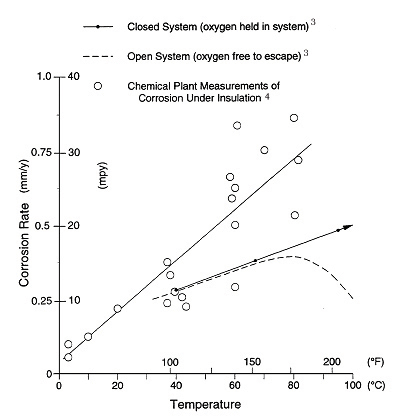
Temperature. It is generally accepted that carbon steel operating in the temperature range of -4°C (25°F) to 149°C (300°F) is at the greatest risk from CUI. Equipment that operates continuously below -4°C (25°F) usually remains free of corrosion. Corrosion of equipment above 149°C (300°F), above the boiling point of water, is reduced because the carbon-steel surface remains essentially dry. Corrosion tends to occur at those points of water entry into the insulation system where the temperature is below 149°C (300°F) and when the equipment is idle. Figure 2 shows the corrosiveness of water versus temperature. The problem of steel corrosion under insulation can be classified as equivalent to corrosion in a closed hot-water system. In an open system, the oxygen content decreases with increasing temperature to the point where corrosion decreases even though the temperature continues to increase.3 In a closed system, the corrosion rate of carbon steel in water continues to increase as the water temperature increases. Estimated corrosion rate data of carbon steel under insulation plotted in Figure 2 that were obtained from actual plant case histories confirm that the rate increases with temperature in a manner similar to that of a closed system.4 It is inferred that the same oxygen cell corrosion mechanism is taking place as in a closed system. The corrosion rates from field measurements are shown to be greater than laboratory tests, due to the presence of salts in the field. Salts increase the conductivity of the water film and thereby influence the corrosion rate.

Insulation. CUI of carbon steel is possible under all types of insulation. The rate of corrosion may vary depending on the characteristics of the insulation material. Some insulation materials contain water-leachable salts that may contribute to corrosion, and some foams may contain residual compounds that react with water to form an acidic environment. The water retention, permeability, and wettability properties of the insulation material also influence the corrosion of carbon steel.

Corrosion of Stainless Steel Under Insulation

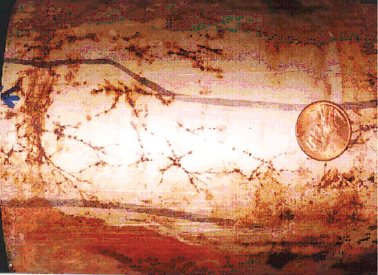
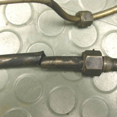
CUI in austenitic stainless steel is manifested by chloride-induced stress corrosion cracking (CISCC), commonly referred to as external stress corrosion cracking (ESCC) because the source of chlorides is external to the process environment. Figure 3 shows ESCC of a 4-inch 304 stainless steel pipe that operated in the 50°-to-100°C range. Figure 4 shows the typical transgranular lightning-strike appearance of ESCC in the pipe. ESCC of austenitic stainless steel is possible when the equipment is contacted by aerated water, chlorides, or contaminants in the temperature range of 50° to 150°C in the presence of tensile stresses.

The Mechanism

A detailed discussion on the mechanism of stress corrosion cracking (SCC) can be found in a number of publications.(5, 6) The mode of cracking is normally transgranular. It is well established that the propensity for ESCC is greatest when the following conditions are present:

  • A susceptible 300 series austenitic stainless steel
  • The presence of residual or applied surface tensile stresses
  • The presence of chlorides, bromide, and fluoride ions may also be involved
  • Metal temperature in the range 50° to 150°C
  • The presence of an electrolyte (water)

Alloys. The stainless steels that are commonly affected by ESCC in the chemical process industries are the 300 series stainless steels, 304 type (UNS S30400 and S30403), 316 type (UNS S31600 and S31603), 317L (UNS S31700), 321 (UNS S32100), and 347 (UNS S34700). It should be noted that other stainless steels could also undergo ESCC under specific corrosive conditions.

Role of stress. For ESCC to develop, sufficient tensile stress must be present in the material. If the tensile stress is eliminated or greatly reduced, cracking will not occur. The threshold stress required to develop cracking depends somewhat on the severity of the cracking medium. Most mill products, such as sheet, plate, pipe, and tubing, contain enough residual tensile stresses from processing to develop cracks without external stresses. When the austenitic stainless steels are cold formed and welded, additional stresses are imposed. The incidence of ESCC is greater in process piping because of the high hop stresses normally present in piping systems. As the total stress increases, the potential for ESCC increases.

Chlorides. Chloride ion is damaging to the passive protective layer on 18-8 stainless steels. Once the passive layer is penetrated, localized corrosion cells become active. Under the proper set of circumstances, SCC can lead to failure in only a few days or weeks. Sodium chloride, because of its high solubility and widespread presence, is the most common corrosive species.5 This neutral salt is the most common, but not the most aggressive. Chloride salts of the weak bases and light metals, such as lithium chloride, magnesium chloride, and aluminium chloride, can even more rapidly crack the 18-8 stainless steels under the right conditions of temperature and moisture content. The sources of chlorides in ESCC are from insulating materials and external sources. The insulating materials include insulation, mastics, sealants, adhesives, and cements. Experience has shown that insulating materials with chloride content as little as 350 parts per million (ppm) can contribute to ESCC. Typically, if the insulating material is the source of leachable chlorides, failure occurs only after a few years of operation. However, external sources of chloride account for most of the ESCC failures. The sources include rain, coastal fog, wash water, fire- and deluge-system testing, and process leaks or spills. Other sources of chloride ions known to be aggressive include chlorine, hydrogen chloride gas, hydrochloric acid, and hydrolyzed organic chlorides. Clearly, the presence of chlorides under acidic conditions is more aggressive than neutral or basic conditions. Failures due to chlorides from external sources tend to occur after 5 or more years of service.

The concentration of chlorides necessary to initiate SCC is difficult to ascertain. Researchers have developed cracking in solutions with remarkably low levels of chlorides—less than 10 ppm. The situation of chlorides under insulation is unique and ultimately depends on the concentration of chlorides deposited on the external surface of the metal. Deposits near ESCC failures have been found with as little as 1,000 ppm chloride. If chlorides are detected, there will probably be some localized sites of high concentration.

Temperature. The most important condition affecting chloride concentration is the temperature of the metal surface. Temperature has a dual effect: 1) Elevated temperatures will cause water evaporation on the metal surface, which results in chloride concentration; and 2) as the temperature increases, the susceptibility to initiation and propagation of ESCC increases. ESCC occurs more frequently in the range 50° to 150°C. Below 50°C, chlorides do not concentrate to levels that cause ESCC. Above 150°C, water is not normally present on the metal surface, and failures are uncommon. Equipment that cycles through the water dew point is particularly susceptible because during each temperature cycle the chloride salts in the water concentrate on the surface.

Electrolyte. Water is the fourth necessary condition for ESCC. Since SCC involves an electrochemical reaction, it requires an electrolyte. As water penetrates the insulation system, it plays a key role at the metal surface, depending on the equipment operating conditions. Examination of the phenomenon of corrosion of steel under insulation provides a better appreciation of the widespread intrusion of water.7, 8, 9 In effect, water may be expected to enter the metal and insulation annulus at joints or breaks in the insulation and its protective coating. The water then condenses or wets the metal surface, or if it is too hot, the water is vaporized.7 This water vapor (steam) penetrates the entire insulation system and settles into places where it can recondense. Because the outer surface of the insulation is designed to keep water out, it also serves to keep water in. The thermal insulation does not have to be in poor condition or constantly water soaked. A common practice in chemical plants is to turn on the fire-protection water systems on a regular basis. This deluges the equipment with water. Some coastal locations use seawater for the fire-protection water. Hot food-processing equipment is regularly washed with tap water, which contains chlorides. All insulation-system water barriers eventually develop defects. As the vessel and insulation system breathes, moist air contacts the metal surface. From the insulation standpoint, the outer covering acts as a weather barrier to protect the physical integrity of the insulation material. The outer coverings are not intended, nor can they be expected, to maintain an airtight and watertight system.
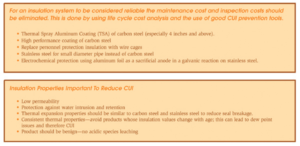
Prevention of CUI

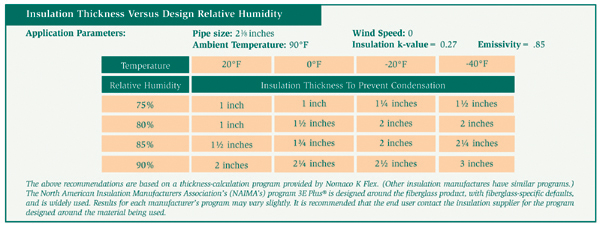
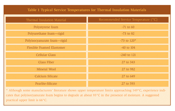
When designing an insulation system the goal is to prevent ingress of moisture. Poorly designed or applied insulation and protrusions through thermal insulation permit water to bypass the insulation, thereby corroding the substrate material. References 10 and 11 provide detailed information on the mechanical design of insulation systems. Attachments to vessels and piping stems are common locations that allow water to bypass the insulation and to concentrate at the attachment point. Examples of such attachments are shown in Figures 5 and 6. Attention to details such as these is important in order to produce a high-quality insulation system. Although the design of the insulation system is important, prevention methodologies based on design alone are not advisable or practical in a chemical plant. The physical characteristics of thermal insulation materials can vary widely. Some insulation materials contain a leachable inhibitor to neutralize the pH of the water in contact with the metal surface. The degree of water absorbency can also vary. For some systems, the coefficient of thermal expansion will influence the system design. For example, cellular glass insulation expands about the same as carbon steel, whereas cellular foam expands nine times more than carbon steel and therefore requires expansion joints. General industry experience over the last 20 years indicates that corrosion is possible under all types of insulation. The common types of insulation materials and their recommended service temperatures are listed in Table 1. Selecting and specifying the correct insulation material can reduce corrosion of both carbon and stainless steels.

Organic coating system. The application of organic coatings on both carbon and stainless steel equipment beneath insulation is an effective method of having a physical barrier to the corrosive electrolytes and thereby preventing corrosion. This method is effective only if a holiday-free coated surface is obtained. In the chemical plant environment, the average life cycle of a coating system is 5 to 13 years.12 In some cases, when a correctly selected and applied coating system is used, a 20-year service life can be achieved. Some of the parameters that need to be considered when selecting a coating system include: coating selection, surface-preparation requirements, environmental requirements, compatibility with insulating material, coating tests, coating vendor selection, specifications, inspection, and selection of a coating applicator. Coating systems that have been used successfully in the process industries include liquid-applied coatings like epoxies, urethanes, and polyurethanes; fusion-bonded coatings; brushable coal tar or asphalt-based coatings; mineralization coatings; and tapes. More information on the selection of protective coatings is available from coating manufacturers’ literature and in Reference 10.

Personnel protection cages. In many instances, thermal insulation is used for personnel protection from hot surfaces. The unnecessary use of thermal insulation creates a location for potential corrosion. In these cases, wire “standoff” cages should be used instead. These cages are simple in design, low in cost, and eliminate the concerns with CUI.

Thermal spray aluminum (TSA). For services too severe for organic coatings, such as temperature cycling above and below 149°C (300°F), TSA provides the best choice for corrosion protection beneath insulation. TSA protects equipment by acting as a barrier coating and serves as a sacrificial anode, protecting the substrate at the sites of any chips or breaks in the coating. The U.S. Navy has demonstrated that the use of TSA results in substantial reduction in the cost of its corrosion-control efforts aboard ships.13 A large petrochemical company has increased the use of TSA in its plant and has shown that large savings can be obtained based on life-cycle cost.12 Over a 20-year cost analysis, the replacement of an existing carbon-steel pipe with TSA-coated carbon-steel pipe compared with the replacement with carbon steel that must be painted at least once during this period resulted in a savings of over 100 percent.12 The development of more-mobile thermal spray equipment with high deposition efficiency is likely to increase the use of TSA in the chemical process industry.

Aluminum foil wrapping of stainless steel pipe. This technique is widely used in Europe by end users and engineering companies, but has not been widely accepted in North America. Aluminum foil wrapping has been used successfully for over 30 years in preventing ESCC by chemical companies in Europe. The aluminum foil provides electrochemical protection by preferentially undergoing corrosion and maintaining a safe potential for stainless steel. The system relies on good weatherproofing and the prevention of immersion conditions. The system can be applied by the insulation contractor and, furthermore, it takes less time to apply than a coating and has minimum substrate preparation.

Wrapping pipe with 46 SWG 0.1 millimeter (mm) aluminum foil can prevent CISCC of stainless steel pipe operating continuously between 60° and 500°C. The pipe should be wrapped with 50 mm overlap, formed to shed water on the vertical line and held with aluminum or stainless wire. The foil should be molded around flanges and fittings. Steam-traced lines should be double wrapped, with the first layer applied directly to the pipe, followed by the steam tracing and then more foil over the top. On vessels, the aluminum foil is applied in bands held by insulation clips and insulation support rings.14

Use of higher alloyed material. To eliminate ESCC, higher-nickel, chromium, and molybdenum-containing alloys (super stainless steels), as well as the lower-nickel, higher-chromium duplex alloys can be used. These alloys are more resistant to SCC and have been found to be resistant to ESCC under insulation. The higher cost of some of these materials makes this option unattractive. However, in some applications the lean duplex stainless steel alloys may offer a low life-cycle cost alternative.

Inspection for CUI

Inspection of insulated piping, vessels, and other components is a major challenge and can be both costly and time-consuming. The goal for the process industries should be to move toward an inspection- and maintenance-free philosophy by using the appropriate corrosion-prevention methods described in the previous section with a focus on life-cycle cost. The American Petroleum Institute code, API 570, “Inspection, Repair, Alteration, and Re-rating of In-service Piping Systems,” (15) identifies corrosion under insulation as a special concern and requires that an appropriate amount of external visual inspection be conducted on piping systems within susceptible temperature ranges. The use of risk based inspection (RBI) assessment conducted in accordance with API RP 580 16 provides a methodology for prioritizing CUI-related maintenance and inspection activities. The intent of using RBI is to manage the probability of failure in piping and vessels while establishing an optimum inspection program. At the same time, a significant portion of the risk in the plant can be addressed by focusing on a relatively few items in the unit. The factors that are usually considered in a RBI analysis include: location of equipment, temperature, materials of construction, age of the equipment, the type and condition of the coating system, insulation type and risk potential in terms of process, business, environment, and safety. Guidelines on how to conduct a visual inspection to detect signs of CUI are detailed in references 10 and 17.

Quantifying CUI in piping in most cases requires the removal of insulation and surface preparation prior to inspection. The cost of insulation removal, inspection, and reinstallation can be very high. A number of nondestructive evaluation (NDE) methods that do not require removal of insulation have been developed to inspect for CUI. The Materials Technology Institute (MTI) sponsored a project to identify and evaluate the effectiveness of several NDE methods.18 The NDE methods evaluated were neutron backscatter, tangential radioscopy, through transmission radioscopy, pulsed eddy current, electromagnetic encircling coils, and three types of ultrasonic guided wave methods. The study concluded that the NDE methods could detect CUI; however, no technique is suitable for every application. The techniques vary widely in several ways, including speed, ease of inspecting piping, detectability of defects, and safety. The factors that influence the ease of inspecting piping include pipe orientation, number of obstacles like hangers and valves tees, proximity to the large metal masses, insulation tie wires, and jacket straps. Detectability of defects is influenced by the orientation, size, and type of defects. It should be noted that the CUI pattern may be nonuniform, and spot nondestructive evaluation may be misleading.

Reprinted with the permission of ASM International.® All rights reserved, www.asminternational.org. Also, please not when citing the original work, this article was published in the ASM Handbook Volume 13C.

References
(1) Private Communications. K. Bartlett, GE Advanced Materials, Evansville, Ind.
(2) Brian Fitzgerald et al—STG 36 Oral Presentation, CORROSION March 2004
(3) F. N. Speller, Corrosion—Causes and Prevention, 2nd ed. (New York, N.Y., McGraw-Hill Book Co., 1935, p 153 and Fig.25)
(4) W. G. Ashbaugh, “Corrosion of Steel and Stainless Steel Under Thermal Insulation,” Process Industries Corrosion, eds. B.J. Moniz, W.I. Pollock (Houston, Texas: NACE, 1986), p 761
(5) Stress-Corrosion Cracking—Materials Performance and Evaluation, Russel H. Jones Ed. ASM International 1992
(6) ASM Handbook Volume 13A, ASM International, Ohio
(7) P. Lazar, Factors Affecting Corrosion of Carbon Steel Under Insulation, in STP 880, American Society for Testing and Materials, 1980
(8) T. Sandberg, Experience With Corrosion Beneath Thermal Insulation in a Petrochemical Plant, STP 880, American Society for Testing and Materials, 1980
(9) V.C. Long and P.G. Crawley, Recent Experiences With Corrosion Beneath Thermal Insulation in a Chemical Plant, STP 880, American Society for Testing and Materials, 1980
(10) NACE standard RP 0198-98, “The Control of Corrosion Under Thermal Insulation and Fireproofing Materials—A Systems Approach,” NACE International, Houston, Texas
(11) J.B. Bhavsar, Insulation Design Practices for Mitigation of Pipe and Equipment Corrosion, Corrosion Under Wet Thermal Insulation, CORROSION 1989 Symposium,
p 15-32, NACE Publication, Houston, Texas, 1990
(12) B.J. Fitzgerald, et al CORROSION 2003, paper No 03029, NACE, Houston, Texas
(13) R. Parks and R. Kogler, U.S. Navy Experience With High Temperature Corrosion Control of Lagged Piping System Components Using Sprayed Aluminum Coatings, Corrosion Under Wet Thermal Insulation, CORROSION 1989 Symposium, p 71-76, NACE Publication, Houston, Texas, 1990
(14) R. Smith, Eutech, Oral Presentation at Stainless Steel World Conference, Netherlands 1999
(15) API 570, Inspection, Repair, Alteration, and Re-rating of In-service Piping Systems, Washington, D.C., API
(16) API 580, Risk Based Inspection. Washington, D.C., API
(17) John W. Kalis, February 2002, Insulation Outlook, National Insulation Association, Alexandria, Va.
(18) MTI project 118, Detection of Corrosion Through Insulation, 1998, MTI, St. Louis, Mo.


Figure 1: Through-wall corrosion under insulation of a large coated carbon-steel storage tank. (Photo courtesy of Paul Powers/GE Inspection).


Figure 2: Effect of temperature on corrosion of steel in water. (This is Figure 12 in ASM Vol 13. Footnote 3 and 4: Corrosion rate unit should be mm/yr.)


Figure 3: Photograph showing ESCC of a 304 stainless steel, 4 inch sch 40 pipe. The piping system was insulated with calcium silicate insulation and operated at temperatures between 50° and 100°C.


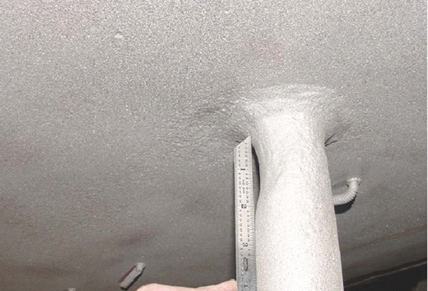
Figure 5: Corrosion of carbon steel where wet insulation was in contact with the surface.


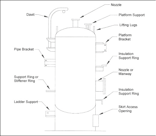
Figure 6: Typical vessel attachments where water may bypass insulation. (Footnote 11)


Figure 7: Attachment to piping where water may bypass insulation. Attachment relies on caulking compound only. (Footnote 11)

Figure 7

Figure 8: (Table 1) Typical Service Temperatures For Thermal Insulation Materials.

Figure 9

Copyright statement

This article was published in the November 2006 issue of Insulation Outlook magazine. Copyright © 2006 – 2018 National Insulation Association. All rights reserved. The contents of this website and Insulation Outlook magazine may not be reproduced in any means, in whole or in part, without the prior written permission of the publisher and NIA. Any unauthorized  duplication is strictly prohibited and would violate NIA’s copyright and may violate other copyright agreements that NIA has with authors and partners. Contact publisher@insulation.org to reprint or reproduce this content.

Disclaimer: Unless specifically noted at the beginning of the article, the content, calculations, and opinions expressed by the author(s) of any article in Insulation Outlook are those of the author(s) and do not necessarily reflect the views of NIA. The appearance of an article, advertisement, and/or product or service information in Insulation Outlook does not constitute an endorsement of such products or services by NIA. Every effort will be made to avoid the use or mention of specific product brand names in featured magazine articles.

Corrosion under insulation (CUI) is the corrosion found under thermal insulation and fireproofing materials. It most commonly results in metal loss, rusting (see Photo 1), or cracking of the insulated components (see Photo 2). It can foul bolt threads, lock critical valve stems, crack instrument tubing, and otherwise interfere with routine plant operations. CUI results in major equipment outages, production losses, and unexpected maintenance costs in refineries and chemical processing plants.

While CUI has occurred as long as hot and cold equipment has been insulated, it was not discussed in scientific journals until the 1950s, and the extent of this damaging corrosion problem was not widely recognized and seriously examined until the 1980s.

The National Association of Corrosion Engineers (NACE International), the American Society for Testing Materials (ASTM), and the Materials Technology Institute (MTI) held a joint symposium on this subject, with speakers from industries worldwide. There was an open discussion on such CUI topics as corrosion mechanisms, methods for mitigation, insulation materials, and inspection. Comparing the various approaches, it was evident that there were many similarities. Most of the attention up to that time had been on bettering the individual components that make up an insulated system. For example, paint manufacturers were concerned with the best paint to apply under the insulation, insulation manufacturers were discussing the merits of cellular glass versus calcium silicate, insulators were concerned about vapor barriers and aluminum versus stainless steel jacketing, and plant inspectors were looking for cost-effective methods to find CUI.

Members of NACE International eventually developed a consensus document to recommend current technology and industry practices for mitigating CUI. Industry representatives on the committee charged with developing the document were from firms producing, specifying, designing, and using thermal insulation and fireproofing products on refinery and petrochemical equipment and piping. The result was the NACE Recommended Practice RP0198-98, “The Control of Corrosion Under Thermal Insulation and Fireproofing Materials—A Systems Approach.”

Although most attention has been focused on corrosion under thermal insulation, fireproofing materials also function—at least in part—as insulation applied between the critical steel structure and a potential fire. A discussion of corrosion mechanisms, the root cause of failure, and corrosion prevention was considered to be the same for corrosion under both insulation and fireproofing in RP0198-98.

The document includes the following six sections:

  1. Section 1—a general introduction to the scope of the problem
  2. Section 2—an explanation of the CUI corrosion mechanisms
  3. Section 3—examples of mechanical design for water-shedding insulation systems
  4. Section 4—a discussion of protective coatings for the insulated components
  5. Section 5—information on insulation and fireproofing materials
  6. Section 6—recommended inspection and maintenance practices

Along with a brief introduction to CUI, Section 1 provides background on past technical approaches to solving the problem.

In its detailed discussion of CUI corrosion mechanisms, Section 2 addresses the two main alloy families affected by CUI: carbon steels and austenitic stainless steels.

Carbon steels corrode, and stainless steels crack—not because they are insulated, but because they are contacted by aerated water. The role of insulation in the CUI problem is threefold. Insulation provides: 1) an annular space or crevice for the retention of water and other corrosive media; 2) a material that may wick or absorb water; and 3) a material that may contribute contaminants that increase or accelerate the corrosion rate.

The corrosion rate of carbon steel and the likelihood of stainless steel cracking vary because they are controlled largely by the temperature of the metal surface and the contaminants present in the water.

Effects and Sources of Water and Contaminants

Given that it is virtually impossible to exclude water from an insulated system, temperatures’ effects play the major role in determining the extent of the corrosion. Figure 3 describes the corrosivity of water in the CUI temperature range.

Inspection of equipment has shown that carbon steel operating in the temperature range of 4°C (25°F) to 150°C (300°F) is at the greatest risk of CUI. Equipment that operates continuously below -4°C (25°F) usually remains free of corrosion, and corrosion of equipment operating above 150°C (300°F) is reduced. However, corrosion often occurs at those points of water entry into the insulation system where the temperature is below 150°C (300°F), at the ice-to-wet transition zones, in equipment in cyclical services, and when the equipment is idle.

As for austenitic stainless steels, the NACE document notes that external stress corrosion cracking (ESCC) “occurs in austenitic stainless steel piping and process equipment when chlorides or other halides in the environment or insulation material are transported in the presence of water to the hot surface of stainless steel and are then concentrated by evaporation of that water. This most commonly occurs beneath thermal insulation, but the presence of insulation is not a requirement. Thermal insulation primarily provides a medium to hold and transport the water with its chlorides to the metal surface.”

Like carbon steel, the temperature range at which ESCC of stainless steels is most likely to occur is not firmly established, but it is generally accepted to be 50° to 150°C (120° to 300°F). Failures are less frequent when metal temperature is outside this range. Below 50°C (120°F), the reaction rate is low. Above 150°C (300°F), water is not normally present on the metal surface and failures are infrequent. However, equipment that cycles through the water dew point is particularly susceptible.

Mechanical Design of the Insulation System

A poorly designed or installed insulation system, or one with penetrations through the insulation, permits water intrusion into the system. Water also enters the system when vapor barriers, weather barriers, mastics, and sealing caulked joints break down over time.

The life of insulated systems can be significantly extended by better design to limit protrusions, attachments, and supports associated with vessels
and piping.

The mechanical design section of the NACE document discusses specification requirements and common specification flaws to be avoided, such as incorrect application of materials, product specification that does not state the properties required, and improper or unclear application methods. The section also discusses the key components of a properly designed insulation system. Drawings are provided to illustrate design do’s and don’ts.

The NACE document then covers how to select protective coatings for carbon steel and austenitic stainless steel. Attempts to prevent water from entering insulated systems though rigorous application of mechanical design principles have not been successful; and corrosion-protection techniques, such as inhibitors and cathodic protection, have been less effective than protective coatings in mitigating CUI. Protective coatings have been recognized and accepted as a highly effective method of protecting insulated metallic substrates from corrosion.

Thus, the consensus is that the basic solution for CUI prevention is the use of a high-quality protective coating. The committee recommends that whenever CUI is a consideration, a protective coating should be employed to protect the equipment before it is insulated. What coating system is most appropriate for protecting the metallic substrate depends on whether carbon steel or stainless steel is being insulated, and on the temperature range of the metal.

Four protective coating systems are listed for austenitic stainless steels. High-build epoxy is recommended for applications in the temperature range of -50° to 140°F. For high-temperature applications to 700°F, modified silicone coatings are recommended. In addition to the coatings, heavy-gauge, aluminum-foil wrapping has been successfully used to prevent ESCC.

With carbon steels, tank lining systems formulated to prevent corrosion are typically recommended for use on steel operating below 150°C (300°F) under thermal insulation. Additional coating systems are recommended for higher operating temperatures. In all, 11 traditional coating systems and a thermally sprayed aluminum coating are recommended in the document.

The Full Range of Factors That Affect An Insulating System

“Users who steam-purge lines shall select a coating capable of withstanding the surface temperature for the duration of the purging. The coating manufacturer should be consulted for specific temperature-resistance information,” the NACE document states.

Another warning concerns inorganic zinc: “Inorganic zinc coatings or galvanizing shall not be used under thermal insulation in the 50°-to-150°C (120°-to-300°F) service temperature range for long-term or cyclic service. Zinc provides inadequate corrosion resistance in closed, sometimes wet environments.”

Section 5 of the NACE document covers insulation, fireproofing, and accessory materials. It describes the properties of industrial insulation, accessories for insulation, and fireproofing materials that affect corrosion. The emphasis of this section is on service performance at specific operating temperatures and the system’s ability to exclude water over the life of the system.

The insulation materials covered in this section include the following:

  • Calcium silicate
  • Expanded perlite
  • Man-made mineral fibers
  • Cellular glass
  • Organic foams
  • Ceramic fiber
  • Historical materials

The section addresses ASTM qualification tests for insulation that is used over stainless steel materials and chlorine content test methods.

Insulation accessory materials include components used to fabricate insulation materials into shapes that fit pipes and equipment, as well as those used to apply the shapes, provide weatherproofing, and seal projections through the insulation system.

In the long term, weather and vapor barriers break down or are damaged to the point that they can no longer keep the insulation dry. So maintenance and inspection of weatherproofing are essential to ensure the integrity of the insulation and fireproofing system. Section 6 addresses inspection and maintenance issues, and presents a checklist of inspection details for new construction.

Insulation on process equipment creates a significant barrier to inspection to detect and assess CUI. Removing all insulation on susceptible equipment is the only way to find all areas affected by corrosion. But this is expensive and may not be practical or allowed for operating equipment. Removing insulation may adversely affect operating conditions.

The section also discusses methods for developing a cost-effective inspection program to mitigate CUI. Factors to be used in determining at-risk equipment include the following:

  • Age of the equipment
  • Type of protective coating on the metal under the insulation
  • Equipment location
  • Operating temperature
  • Construction materials
  • Consequences of a leak

Once the high-risk equipment has been identified and an inspection work plan developed, trained inspectors should conduct a visual examination following the key indicators for CUI listed in this section of the NACE document. Additional nondestructive examination techniques to enhance, but not replace, the visual inspection also are listed.

It is clear that a systems approach to controlling CUI is necessary. With the use of modern coatings technology, selection of appropriate insulation materials, and good installation practices, it is reasonable to expect cost-effective insulated piping and equipment to provide 20 to 30 years of reliable performance.

Figure 1

Photo 1

Figure 2

Photo 2

Figure 3

Figure 3

The primary cause of insulation system failure is improper installation and/or design of the outer lagging. If insufficient consideration is given to the lagging in the design stage, the result may be a lagging system that is improperly installed. This is why the power industry will spend more than forty million dollars in the next five years reworking existing insulation and lagging systems on new air pollution systems. Good lagging practices must be enforced from the design level to the finished product, and it all begins with a good lagging specification.

Some readers may be familiar with “Writing an Insulation Specification” (published in this magazine in July 2005). The procedures for developing a lagging specification are very similar to those procedures. Similar to an insulation specification, a lagging specification should do the following:

  • Convey to the lagging installer, clearly and without exception, the intent of the specification.
  • Have enough information necessary for the installation to proceed without stating what is not required or necessary.
  • List only the things required for the proper installation of the lagging system to the scope, as defined in the specification.
  • Work hand in hand with the insulation system being utilized.
  • Be broken down into four major divisions: General Conditions, Scope Definition, Material, and Application.
  • The General Information section states what the job conditions are, such as storage, warehousing, and specific responsibilities.
  • The Scope section sets the boundaries within the specification.
  • The Material section states clearly what materials can be used.
  • The Application section states clearly, either by written specification and/or application drawings, the minimum requirements and accepted standards for applying the material.

In an insulation specification, the amount of information required for a proper install can be somewhat minimal. Insulation specification contents tend to provide just enough to give the installers the flexibility to make some choices on the external stiffeners (hump, bury, or use an inner support). However, in regard to the physical application of the material (attachment spacing, gaps between the insulation, double layer versus single layer), the insulation specification must state clearly what is required for a proper application, with no room for deviation.

When it comes to a lagging specification, more detailed information must be included, with much less flexibility given to the installer. The industry has lost a lot of expertise in installing lagging on hot applications (over 350°F). Lagging installation requires the installer to have imagination and skill, very much like the carpenter who trims out a house. You would not want an inexperience person trimming out your new home. Similarly, it takes an experienced craftsman to design and install lagging on an air pollution system operating at 700°F. The individual must consider aesthetics, watershed, weather protection for the insulation under the lagging, and the expansion that sometimes occurs in two directions. Also, due to the short erection schedules, many air pollution projects require the lagging to be installed while the unit is in operation.

Unfortunately, the current lack of experience appears to be industry-wide, due to the prevalent use of nonconventional labor in the application of sheet metal, lack of training related to good lagging practices within the industry, lack of accepted industry standards for installing lagging, and lack of major capital improvements or new boiler work in the power industry. It is only in recent years that the power industry has had major projects that involve hot flue, duct, air pollution equipment, or new boilers. Since major projects are few and far between and involve shorter outages, the number of people experienced with the hot systems associated with a power plant is diminishing. When a major capital improvement project takeplace, the workforce pool must include those who have little or no experience working at power plants on equipment that will be operating at elevated temperatures.

These issues potentially cost the power industry millions of dollars, which is one reason why the American Society of Mechanical Engineers (ASME) just announced a new Continuing Education Institute short course on lagging. It is recommended that all plant managers, plant engineers, plant operators, maintenance personnel, professional and service engineers, and installing contractors take this course.

Like the insulation specification, the lagging specification—when properly prepared—will be used as a guide for the installer. It should include a quantitative takeoff of both the lagging and the insulation being installed. Lagging may be the last thing installed, but it must be the first thing considered when designing an insulation system. The lagging specification always must take into account the insulation system being utilized and the operating conditions of the equipment being insulated and lagged.

In years past, it was common practice for original equipment manufacturers (OEMs) to include only a few general lagging application drawings with their specifications. The OEM companies assumed—and rightly so—that those installing the lagging would be able to do so properly taking into account expansion, watershed, and aesthetics. Unfortunately, that was then, and this is now. Today, a good lagging specification must include application drawings that clearly show how to flash around doors and penetrations, install corner flashing, deal with watershed, account for expansion in long vertical lagging surfaces, or install lagging when the unit is in operation.

Sample Lagging Specification

Good lagging installation begins with the specification. Here is one example of a complete lagging specification without the drawings.

Scope

These specifications cover the lagging material and application for the hot selective catalytic reduction system (operating at 700°F), including new flue work from the boiler gas outlet to the air heater gas inlet. All materials and their application must be in accordance with the following pages and in accordance with any and all reference drawings.

General Information

The installer shall perform all phases of work and supply all materials required in an acceptable manner, as shown on the drawings and documents submitted with these specifications. The quantitative takeoff provided with these specifications is intended as a guide solely for the purpose of defining the scope of work. It is the installer’s responsibility to verify material types and quantities. Nothing in these specifications relieves the installer of the responsibility to verify quantities or types of materials being provided.

Materials furnished by the installer shall be unloaded, stored, and weather-protected by the installer until applied. On coastal jobs, even with inside storage, contamination and discoloration can occur from atmospheric condensation between sheets when laid flat. Routine inspections should be carried out; if any condensation is found to be forming, sheets should be separated and ventilated.

The installer shall furnish all supervision, labor, tools, and equipment—including, but not limited to compressed air, scaffolding, dry storage, office, and change room facilities—necessary to install all materials furnished under these specifications.

All materials being furnished under this contract must be asbestos-free. The company shall reject any and all asbestos-containing materials.

The customer’s premises must be kept reasonably clean during construction and broom clean prior to leaving the job at completion.

The successful installer, afterward, shall submit a final as-built bill of materials listing the quantities and sizes of the materials used/required to complete the lagging requirements. This bill of materials should include the material manufacturer’s name and extra quantities included for wastage.

Application

All materials required for proper support and fastening of the lagging shall be supplied and installed by the lagging installer. This will include, but not be limited to clips, bands, studs, angle iron, screws, etc. All attachments must be installed on proper or specified centers for the support of the lagging materials. See win loading chart below.

On systems operating above 350°F, the lagging must be installed in direct contact with the insulation wherever possible. When the lagging is not installed in direct contact with the insulation, expanded metal 1½” x 18ga c.s. must be installed over the face of the insulation.

Rib lagging should always be used wherever possible in lieu of flat sheet because it helps in expansion and contraction of the lagging system. Flat sheet, in most cases, should be used for flashing, round surfaces, elliptical or irregular surfaces such as drumheads, and areas where space prohibits the use of rib lagging.

All flashing shall be cut to fit and fabricated in the field from flat sheet or coils. No prefabricated corner flashing should be used.

Expansion must be incorporated into the lagging design. All lagging should be applied over insulated areas so as to present a true plane, stiffened and fastened on adequate centers to prevent excessive deflection or “oil canning” when hot or cold. Necessary provisions for expansion and contraction must be provided to maintain a neat and proper design when in service.

All lagging supports (sub-girt, Z or H type support, angle iron) should be installed utilizing short spans, with a maximum length of ten feet wherever possible. A small gap must be left between support assemblies equal to the amount of expansion expected in that direction. In no case should the short sections of the support system be welded or screwed together.

When caulking seals the lagging system, it must not restrict or hinder the contraction or expansion of the lagging. The materials used for the caulking must be consistent with temperature limitations and expected expansion and contraction to be encountered.

All the lagging attachments used should always be spaced in set patterns, both vertically and horizontally, to present a uniform appearance. They also should be located on adequate centers to prevent rattling or “oil canning” due to expansion or vibration, Insert MISSING TEXT HERE

Expansion joints located in the flues will take up most of the expansion or contraction of the equipment being lagged. The lagging over the expansion joints should be designed so as to provide movement equal to the expansion of the joint covered.

For lagging support spacing on any given area, the maximum allowable spacing should always be utilized. (See typical wind loading and support spacing charts)

Material

Ribbed type lagging material shall be clad 3004 alloy. The cladding is to be 7072 alloy. The core material shall conform to ASTM B-209. The depth of the ribs shall not exceed 2½ inches overall. Lagging material may be furnished in precut custom lengths or in standard mill lengths.

Flat lagging material shall be clad 3003 alloy. The cladding is to be 7072 alloy. The core material shall conform to ASTM B-209.

All exposed surfaces of the lagging material shall have a stucco-embossed finish unless otherwise specified in these specifications.

All lagging materials shall be of such temper so that the lagging material shall bend flat on itself without cracking.

  • Temper for the rib type lagging shall be H-174.
  • Temper for the flat lagging shall be H-154.
  • The mill finish flat sheet shall have a temper of H-14.
  • The thickness of the rib lagging shall be a minimum of .032 inches.
  • The thickness of the flat lagging shall be a minimum of .040 inches.

The lagging system must be of a design and thickness so as to withstand a minimum of thirty pounds per square foot section or pressure wind loading over a single span. Fasteners shall be spaced with a maximum spacing of three-foot by two-foot centers. Stitch screws should be installed on twelve-inch maximum centers.

All attachments (such as clips, bands, studs, screws, etc.) shall be supplied by the installing contractor. The screws shall be zinc plated, stainless steel #14, with hex head, type A-B, or tek type.

Conclusion

A lagging specification must convey to the installer, clearly and without exception, the intent of the specifications and must include detailed lagging application drawings. These detailed drawings will help an inexperienced workforce understand the level of quality required when installing lagging on flues, ducts, steam-generating boilers, and air pollution equipment. The right lagging specification is the first step to a good installation. If little consideration is given to the lagging in the beginning of the insulation system or equipment design, the result may be a lagging system that is improperly installed. Good lagging practices must be enforced from the design level to the finished product.

Lagging may be the last thing installed, but it must be the first thing you think about when designing flues, ducts, air pollution equipment, or insulation system—and it begins with a good lagging specification.

Natural gas is a natural source of energy now exploited extensively around the world. It is clean, efficient, and environmentally friendly. It can be transported via pipelines or in tankers in liquefied form. Liquefaction is achieved by refrigerating it to -160°C, reducing its volume by over 700 times, which yields liquefied natural gas (LNG). Natural gas producers with surpluses over their domestic requirements, as well as consuming nations without their own domestic supplies or access through pipelines, have provided the catalyst for the growth of the LNG market.

At the end of 2004, total proven world gas reserves were around 180 trillion cubic meters, the vast majority of which was in the Middle East and Russia. Demand for natural gas is growing at rates in excess of 10 percent in Europe, the United States, and China. Investment in the next 5 years is expected to be two and a half times that of the last 5 years. China and India have now entered the market for imports. Large producers of natural gas such as Russia, Iran, and the U.S. Gulf states are committing to LNG production. The leading producers of LNG are Indonesia, Malaysia, Qatar, Nigeria, and Venezuela. The major consuming nations are Japan, Europe, and the United States.

As natural gas travels from underground to the final user, industrial or domestic, it moves through pipelines, a processing plant, storage facilities, and various methods of transportation. From the gas field, it is piped to the export terminals, where the gas is purified, compressed, and liquefied in LNG trains. It is stored in large holding tanks to await transportation by sea in purpose-built LNG tankers to the import-receiving terminals where it is again stored. It is then restored to its gaseous state before being fed into the gas transmission system, which brings it into our homes. LNG has no smell, so a further process at the import terminal involves giving it an odor so that leaks can be detected.

Typically, an LNG process train will produce around 6 billion cubic meters of gas annually. The world’s largest LNG export terminals currently comprise six to eight trains. The storage tanks typically hold up to 200,000 cubic meters per tank. Owners are beginning to build “super trains” capable of doubling production capacities. Some 18 LNG export terminal projects are expected to be built around the world within the next 5 to 10 years, with at least another 17 planned. For each export terminal, there is a corresponding requirement for LNG tanker and import terminal capacity.

The development of LNG, from the late 1970s on, presented a challenge to thermal insulation manufacturers and contractors. An industry primarily concerned with heat conservation had to engage with owners to find solutions—not only to the conservation of very low temperatures, but also to the particular stresses involved at those temperatures. As one of the pioneers, Shell developed many of the specifications, enshrined in its Design and Engineering Practices (DEP), now CINI.

For these plants to function, efficient insulation systems are needed for cryogenic service. When a plant is operating at -160°C, the environment is unforgiving. Inefficient insulation will result in much higher refrigeration requirements as the boiloff is increased. Ineffective vapor barriers will allow moisture to enter the insulation system, causing icing and major disruption. The relative movements between the plant, the equipment, and the insulation systems due to thermal contraction and expansion as they cool down or warm up become major considerations. Complex insulation systems are required to withstand the rigors of differential expansion and contraction, thermal shock, and vapor drive.

Most of the insulation systems adopted have involved the application of multiple layers of preformed insulation sections with appropriate slip joints, vapor barriers, and expansion and contraction joints and claddings.

Multilayer, rigid, preformed insulants such as polyisocyanurate (PIR) foam or cellular glass with staggered joints—often with wet-applied primary and secondary vapor barriers—are the proven means of insulating LNG plants. The systems are tested and—like most systems—require close, rigorous quality control (QC) and protection from adverse weather conditions. They are also labor intensive. A combination of the two insulants can be used, depending on the importance of overall insulation thickness as a requirement for additional mechanical strength and/or fire protection.

A variant has been the combination of rigid, preformed, and injected PIR (foamed in situ). With the preformed material providing the inner layer and the injected material the outer, this provides a cost-effective, labor-saving specification. Further, it requires no separate vapor barrier, as the injected foam adheres to the inside of the outer cladding. The performance of the primary vapor barrier relies on the integrity of the foam to the cladding-adhered bond and the effective sealing of cladding overlaps. The controlled mixing of chemicals in a site environment requires particularly tight QC, and the technique is not easily applied during inclement weather.

Outer-cladding protection has taken the form of sheet metal, as with heat-conservation systems. Given the saline and chemically sensitive environments in which LNG plants tend to be built, however, corrosion has been a problem. Specifiers often opt for 316L stainless steel and aluminized steel.

The application of such complex insulation systems on site is likely to involve production rates of between 5 and 10 man-hours per square meter, and is therefore very labor intensive. The insulators and sheet-metal workers require a hierarchy of supervision, quality assurance (QA) inspectors, and material controllers. At the outset of the project, the manpower loadings are smoothed to provide efficient utilization. As the project proceeds, delays inevitably occur and, as one of the back-end activities, the insulation application is also delayed. As project management tries to keep the completion date from slipping, more manpower is required, resulting in increased labor and all of the associated resource and cost consequences. Increased manpower results in other, less tangible, costs—particularly the potential delay of project completion. Many of the LNG sites around the world do not have sufficient local accommodations and so require the labor to live in camps, and additional people require appropriate facilities. Manpower requirements typically rise from 300 to a peak of 700 or 800 personnel. Finding skilled personnel to carry out such complex work makes great demands on recruitment, training, housing, and management. Clearly, anything that can be done to successfully complete the insulation work earlier in the project—from decoupling from the main construction to reducing the labor content—will help both the client and the contractor achieve their goals.

As the demand for gas accelerates, the number of new plants increases. Owners are looking for reduced construction programs and shorter completion times. Also, there is a continual squeeze on costs. The challenge for the successful contractor is to find innovative ways to perform the insulation work on this type of plant.

Preinsulation of straight pipework is a way to get a percentage of the work completed earlier in the project and avoid the delays caused by other trades. Pipes can be sent directly from manufacturers to a factory location where the insulation can be applied in controlled conditions. An effective system that can be applied in this environment involves sprayed PIR foam covered with a glass-reinforced epoxy coating. The system, proven on a number of Shell installations, incorporates crack arrestors and slip joints, and a resilient inner layer that allows for thermal and mechanical contraction and expansion. It provides a low-maintenance, high-performance cryogenic insulation with a robust, chemical-resistant, noncorrosive finish. While resistant to mechanical damage, it also accommodates the stresses and strains associated with thermal cycling—particularly those that are associated with the jetty lines. The result is a high-quality insulation and finish applied in factory-controlled conditions.

Another area for attention is the primary vapor barrier, which involves many man-hours in application and critical QC inspection. Traditionally, vapor barriers have been applied as wet systems, but costs can be high due to the composition and low manufacturing volumes. These materials also have shelf-life issues, which can have a major impact if projects are delayed. The vapor barriers are normally applied in three layers, with glass cloth reinforcement applied between the layers. Alternatives to the wet-applied systems are required to speed application and reduce the necessary QC. A number of laminates in sheet form, such as butyl laminate, are becoming available. Insulation suppliers are also developing their products with factory-applied coatings.

The advent of ultraviolet-cured glass-fiber reinforced plastic (GRP) offers another external cladding system. With mylar foil double, it can be used as a vapor barrier, avoiding the need for wet-applied vapor barriers. Supplied in flexible sheet form and cured by natural or artificial light, ultraviolet-cured GRP provides a seamless, successful alternative to the traditional metallic cladding finish for complete plants. The recent reinsulation of the cryogenic heat exchangers at Brunei LNG was successfully undertaken with such a finish. These advancements lead the way as the industry strives to innovate and improve.

The significant investment taking place in this area is making demands on available skills; and in the mature markets in Europe and the United States, there is limited skill available in “cold” insulation, for lack of demand. It is important that the industry continues to develop ways to help clients meet demanding cost and program budgets.

The insulation industry has an interesting time ahead as it continues to rise to the challenge of insulating the world’s latest generation of LNG plants in an efficient, cost-effective, and timely manner.

Good design for architectural acoustics can be relatively straightforward when applied in the design phases of the project. Acoustics problems can be very difficult to fix, however, after a facility is built.

Rather than consult with a qualified acoustics consultant in the design phase, an owner or architect often will call in an insulation contractor to try to fix noise and sound isolation problems by applying fiberglass or mineral wool insulation to noisy ducts or piping or above a drop ceiling. This approach—“sticking some acoustics” on a problem—is rarely successful. This article discusses what can-and cannot-be accomplished using insulation in noise control.

The Properties of Sound

Sound is a pressure wave. It may be helpful to visualize sound waves like a slinky. Imagine a column of air traveling through space, alternately compressed and rarefied.

The speed of sound is approximately 1,130 feet per second. Compare that to the average speed of air in a ducted system, on the order of 1,100 feet per minute, or 1/60 the speed of sound. Sound travels about as well upstream as it does downstream within ductwork, and fans are perceived as noisy on both the supply (downstream) and the return (upstream).

Sound waves have size, too. Though people normally talk about sound in terms of frequency (Hz), the wavelength (size) of a particular sound partially determines the means needed to treat it. The performance of sound-control treatment depends on the dimensions of that treatment relative to the wavelength of the sound.

For example, high-frequency sound—such as the high-pitched hiss one might hear as air leaks from unsealed ductwork—has a short wavelength. The dimension of the wavelength of this sound is about the size of the seam in the duct. Noise in this frequency range can easily be treated with mineral fiber insulation.

On the other hand, low-frequency sound—such as the rumble one hears when standing next to a large fan or air-handling unit—has a long wavelength. About the size of the machine itself, this cannot be successfully treated using mineral fiber alone.

The loudness, or amplitude, of a sound wave is usually expressed in decibels (dB). Sound measurements in dB are typically made in each of eight “octave bands” covering the entire audible range from very low to very high frequency. A particular sound-level measurement typically yields eight separate dB values corresponding to the loudness in each of the eight octave bands. These eight octave-band measurements are simplified into a combined single-number representation known as dB(A). A particular eight-octave band sound measurement describes a sound spectrum, and the single-number simplification of dB(A) provides a fairly easy way to show how loud various noises sound to the human ear. It should be noted, however, that dB(A) is a simplification used for convenience.

Other Useful Terms
Structure-borne Versus Airborne Noise

Audible noise frequently results from vibration transmitted into the building structure and re-radiated out elsewhere as noise. This is structure-borne noise. Noise that results from structure-borne vibration cannot be effectively treated using insulation materials, or even using additional massive construction. This class of problem can only be treated using vibration-isolation and/or
structural-isolation techniques.

Transmission Loss (TL) and Sound Transmission Class (STC)

TL is a measurement applied to common structures and components used for containing sound-including doors, walls, windows, floors, and ceilings—and to composite external wrapping of equipment, piping, and ductwork commonly referred to as lagging. Both TL and STC are ratings of the amount of sound blocked from passing through a structure. They are most often applied to wall construction, and door and window types.

Sound travels wherever air can travel; unless a wall is not airtight, sound does not really go “through” it. The mechanism works more like this: Airborne sound strikes one side of a solid wall, the wall responds by vibrating, the vibrating backside of the wall becomes a radiator of sound, and sound becomes audible on the other side of the wall.

STC is a single-number simplification of the amount of sound transmitted through a structure. It is strictly limited to speech frequency and is not at all applicable when discussing noise problems related to mechanical equipment, which typically occur at lower frequencies. When comparing STC ratings of various partitions, it should be noted that equivalent STC ratings do not imply equivalent performance at all frequencies.

Here are some common STC ratings:

  • STC25—Normal speech is transmitted audibly
  • STC30—Loud speech is heard clearly
  • STC35—Loud speech is blurred but intelligible
  • STC40—Loud speech is heard only as a murmur
  • STC45—Loud speech is heard only by straining
  • STC50—Loud speech is totally unheard

    Sound Absorption and Noise Reduction Coefficient (NRC) Rating

    NRC rating is commonly applied to acoustic tile ceilings and fabric-wrapped acoustic wall panels.

    When a sound wave strikes a surface, one of three things can happen: The sound is reflected away from the surface, is transmitted through the surface, or is absorbed by the surface. The NRC rating of a material is a measure of the amount of sound absorbed by that material in a particular installation and within a certain range of sound frequencies. The higher the NRC rating, the more sound is absorbed by that material.

    Noise criterion (NC), room criteria (RC), and dB(A) are all single-number simplifications that describe background noise level. Each is a representation of the sound spectrum, and NC and RC are often used as design targets for sound-sensitive spaces. The higher the number is, the louder the background noise levels. Here are some examples:

  • RC-35—Typical classroom design
  • RC-25—Church
  • RC-15—Concert hall or recording studio

    In addition, dB(A) often is used for outside noise and in municipal ordinances to describe maximum permissible noise level at a property line. The chart below shows some common equipment noise levels. Note which frequency dominates in each example.

    The dominant audible noise frequency of the transformer appears in the 125 Hz octave band. Fiberglass insulation is most effective in treating noise at 500 Hz and above. The transformer does not generate much noise in the upper frequency bands, so it is difficult to treat its noise using fiberglass alone. The airborne noise level of 70 dB at 63 Hz usually can be contained by normal construction methods. However, the transformer should be mounted on vibration-isolation mounts to keep the 125 Hz hum out of the building structure.

    The dominant frequency of the screw chiller appears in the 250 Hz octave band. Mineral fiber insulation alone is not particularly effective in the 250 Hz frequency band, so wrapping a chiller in mineral fiber will not do much good. One can install a chiller in a room lined with a 2-inch-thick insulation system and achieve significant noise reduction in the room. No amount of treatment within the room will keep sound energy at 250 Hz from transferring through the building structure and reappearing elsewhere as noise, however.

    In any sound-sensitive application, a chiller like this must be supplied with vibration-isolation mounts. In addition, structural isolation of chiller rooms often is required in sound-sensitive applications.

    The dominant frequency of the rooftop air-handling unit appears in the 63 Hz octave band. Fiberglass alone is ineffective in treating noise at 63 Hz. However, sufficient length of 2-inch internal fiberglass duct lining can provide significant noise reduction in all of the upper frequencies, and it makes an enormous difference in the amount of audible duct-borne fan noise transmitted by an air handler like this.

    Areas Where Fiberglass Insulation Is Effective In Treating Sound

    Insulation contractors are often faced with the challenge of solving equipment noise problems, improving sound isolation, or managing other acoustic problems in buildings after design and construction are complete. Unfortunately, most acoustics problems are difficult to address postconstruction. Of those that can be dealt with at this point, only a few can be successfully addressed by an insulation contractor. These are identified and discussed below.

    Sound Treatment of Mechanical and Electrical Equipment Rooms

    The noise output from multiple sources in mechanical and electrical rooms can reach unacceptably high levels. This noise can be easily transmitted through the walls and break through duct walls. It is also transmitted via conduit and piping as vibration. Lining the interior surfaces of the mechanical room with an absorptive material can be beneficial. Normally, 2 inches of 3 pound/cubic foot density fiberglass board is recommended. Typical application would consist of 50-percent coverage evenly distributed on the walls and 100-percent coverage on the ceilings. If a room is subject to abuse (where the fiberglass board would be damaged), the wall finish might include cementitious wood-fiber panels on a C-40 mounting over the fiberglass board.

    Improving Interior Room Acoustics and Speech Audibility

    Similar to (and more familiar than) sound treatment of mechanical rooms, mineral fiber treatment of occupied spaces provides control of echo and reverberation in a room. It also greatly improves speech audibility in these spaces. Products used in these spaces include high-NRC acoustic ceiling tile, fabric-wrapped acoustic wall panels, and occasionally mineral fiber batt insulation in the ceiling cavity. These materials are not typically provided by the insulation contractor, however.

    Improving Performance of Wall Construction

    There is a relationship known as mass law that states that the TL performance of a wall is related to the mass of the wall (among other factors). The end result of this relationship is that one achieves a 5-dB improvement for every doubling of the mass of the wall.

    So, for example, at 1,000 Hz, a 4-inch dense poured concrete wall provides roughly 44 dB of transmission loss. An 8-inch dense poured concrete wall provides 49 dB. A 16-inch dense poured concrete wall provides 54 dB, and so on. If constructed strictly of dense poured concrete, a high-performance wall quickly starts to become massive.

    If, on the other hand, a lighter-weight double wall is provided, with a mineral fiber-filled airspace in between two 8-inch solid core concrete block walls separated by an 8-inch airspace (and not structurally connected), one would have 10 to 15 dB better performance at 500 Hz and above than a single 12-inch, solid-core concrete block wall.

    There are other tricks to this type of construction, but the end result is that the internal airspace provided with absorptive material such as mineral fiber will “decouple” the two walls and radically improve performance of the partition. This type of wall construction has to be designed into the project, though. There is little chance of solving a sound-isolation problem in an existing wall via the introduction of fiberglass.

    Services Penetrations

    An additional, often overlooked step in providing the best possible sound-isolation performance in wall construction is the proper airtight sealing of all service penetrations. This includes ductwork; sprinkler piping; domestic and circulating water; waste lines; and conduit penetrations in walls, floors, and ceilings. All of these penetrations can transmit airborne noise and structure-borne vibration, depending on what they are connected to.

    All penetrations in acoustically sensitive areas, as well as mechanical and electrical equipment rooms, should be acoustically sealed airtight to minimize noise and vibration transmission. Most pipes and conduit less than 1½ inches in diameter can be grouted airtight into the wall, but other penetrations should be sleeved so that they are ½ to 1 inch larger than the object penetrating the structure. The resulting clearance should be packed loosely with glass or mineral fiber and should be caulked on both sides with a nonhardening, resilient acoustic caulk.

    Although these penetration details typically fall to the general contractor, there can be a fair amount of mineral fiber packing required for proper sealing of penetrations in acoustically sensitive applications.

    Duct Liner and Sound Attenuators

    Attenuation of duct-borne fan noise can be accomplished by installing a combination of prefabricated sound attenuators and internal duct lining. Standard coated 1- and 2-inch duct linings should be used in all low-pressure ductwork serving acoustically sensitive spaces. Half-inch duct lining should never be used, for acoustical reasons. The lining should be coated and have a density between 1½ and 3 pounds per cubic foot.

    As noted earlier, because the speed of sound is much higher than normal system velocities, sound travels upstream almost as well as it does downstream. Thus, fan noise control is as important in return ductwork as it is in supply ductwork. Attenuators and duct lining are usually recommended on both the supply and return sides of the fan system.

    Although this is a good example of how fiberglass is used well to control noise, fiberglass duct liner and fiberglass-filled prefabricated sound attenuators are typically provided by the sheet metal contractors.

    External Wrapping of Noisy Pipes and Ducts

    Wrapping noisy ducts and pipes with fiberglass alone is almost never successful in treating noise problems. This is because the noise problem is almost always a mid- to low-frequency problem, with a wavelength that is too large to be treated by an inch or two of fiberglass. However, coupling the insulation with an external massive barrier can have significant results. This is an approach insulation contractors can take when faced with a similar noise problem. See the example below.

    This may be the ideal situation where an insulation contractor can provide a useful reduction in noise after construction is complete. The technique can be applied for noisy circulating water piping, waste lines, rain leaders, and even duct work. When lagging duct work, an airtight, multilayer gypsum board soffit should be substituted for the loaded vinyl external jacket.

    Areas Where Fiberglass Insulation Is Not Effective in Treating Sound

    Areas where the installation of fiberglass insulation is not effective in treating sound are discussed below.

    Mechanical Room Doors and Penetrations

    No amount of insulation mounted to the walls of a mechanical room will overcome the effects of a poorly selected or ungasketed door. Where doors to mechanical rooms adjoin acoustically sensitive spaces, they must be gasketed at the head, jambs, and threshold. Such doors must not be supplied with louvers, undercuts, or transoms.

    In addition, air intake and exhaust air openings must be located where mechanical noise cannot reenter the building through doors, windows, ventilators, or smoke vents; and where it will not affect use of outdoor spaces.

    Structural Isolation

    As in the case of installation of both screw chillers and large air-handling units, mechanical room noise is often intense enough to excite the mechanical room surfaces. If these surfaces are structurally continuous with those of acoustically sensitive or critical spaces, noise and vibration may be transmitted to those spaces. In such cases, there must be structural separation between mechanical rooms and acoustically sensitive or critical spaces. If structural separation and massive double construction (including floating concrete floors) are required, simply applying insulation will not work.

    Noisy Grilles, Registers, and Diffusers

    Mid- to high-frequency noise at the face of a supply air diffuser or return air grille is usually generated at the device. High-velocity air flowing over the face of the diffuser or grille makes noise. The more restrictive the design, the more noise it generates. There is little that can be done by the insulation contractor in these situations, other than to suggest reselecting the grilles and diffusers.

    Although much depends on the design of the diffuser or grille, the following recommendations are for air velocities in supply and return branch ducts for various target-background-noise levels.

    Vibration Isolation of Mechanical and Electrical Equipment

    Almost anything that has moving parts or handles the flow of gas or liquid vibrates to some degree. Rigidly attaching any vibrating machine or conduit to a structure will transmit that vibration into the structure. This vibration will likely manifest itself as audible noise above, below, adjacent to, or perhaps (surprisingly) far away from the offending piece of equipment.

    Good candidates for vibration isolation include:

    • Chillers
    • Compressors
    • Pumps
    • Fans
    • Air-handling units
    • Large circulating water piping (connected to pumps)
    • Rooftop air handlers and fans
    • Transformers

    To isolate equipment vibration, mount the equipment on properly selected spring or neoprene isolators, then attach all connected services (ducts, pipes, and conduit) resiliently so that the main piece of equipment is free to “float” on the isolators. Often when there is a loud rumbling or tonal noise in a space adjacent to a piece of equipment like this, the problem is with the vibration isolation of that equipment. In this situation, all an insulation contractor can do is point out to the owner or architect that structure-borne vibration may be the source of the noise due to direct coupling of the equipment to the building structure.

    Summary

    Insulation materials are often used to solve acoustics problems. They can be useful in controlling room acoustics parameters like reverberation and echo, and for controlling the buildup of sound, or loudness, within a space. They also can help reduce the loudness of sound within a mechanical equipment room or improve speech intelligibility within a classroom. Insulation materials can improve sound isolation between adjacent spaces, and quiet noisy pipes and ductwork, but this is usually effective only when used in combination with more massive materials.

    Mineral fiber insulation materials are of no use, however, in the control of generated noise problems at grilles, registers, and diffusers, or for the control of structure-borne noise and vibration. If a contractor, owner, or architect suspects a vibration-isolation or structure-borne vibration problem as the source of a noise problem, he or she should get advice from an experienced acoustics consultant.

  • In an era of reorganization, mergers, and globalization, the power industry—along with the insulation and lagging industry—requires a well-educated workforce to remain profitable and competitive.

    In addition, a commitment to fundamental insulation research is necessary to provide future innovative solutions and technological developments for the insulation producer being used in power plants. Achieving these two goals requires not only a coordinated commitment to education and research programs from the sectors of insulation engineering, science, and technology, but also effective networking of these academic and industrial concerns for a qualified workforce.

    Working in the power industry is not the same as it was twenty years ago. Outages are smaller, and the workforce has aged. Power plant and original equipment manufacturer (OEM) staffs no longer have the expertise to monitor the proper installation of insulation and lagging. Also, the workforce used to install insulation and lagging on very large projects, such as new air-pollution equipment and new boiler installation, but has little or no experience working at power plants.

    Given both the limited experience and the fact that the number one reason insulation systems fail is improper installation and/or design of the insulation and lagging system, the need for continuing education is clear. Systems are failing because designers and installers fail to understand the fundamental differences and problems that occur when using low-temperature insulation and lagging systems on high-temperature applications. A continuing education course should address this issue as well as others pertaining to boiler expansion, lagging aesthetics, water shedding, and the proper application of insulation on boiler walls, flues, and ducts with external stiffeners.

    Working at a power plant requires a special understanding of all the different types of boilers, their unique operation requirements, the high multidirectional expansion that can occur, and the parameters for installing the materials while the boiler is in operation.

    But how many people working in the power industry really know or understand the basics of thermal calculations—or even what constitutes a proper install for a lagging and insulation system?

    Most people are unaware of the six keys to understanding heat flow or thermal calculations: wind velocity, ambient air temperature, surface temperature, K-value, emissivity factor, and the operating temperature of the system being insulated. Most do not know that proper calculation of insulation thickness and material types saves money at the initial installation, allowing them to pay only for what they need. On the long-term investment, then, minimizing the amount of heat loss that radiates from the outer casings or lagging surfaces saves energy and money. The power plant will use less fuel to reach and maintain a boiler’s operating conditions.

    The proper design and installation procedures for insulation and lagging are essential for thermal and energy efficiency, which is critical to lowering the amount of energy or fuel (oil, gas, coal, refuse) required to make electric power. President George W. Bush once noted, “Energy is a problem that requires action—not politics, not excuses, but action.” Clearly, that action should be applied to industries that have a direct impact on the amount of fuel used in the power-generating industry.

    It is important to educate the power-generating industry workforce, including the labor and the plant personnel. All should have a working knowledge of every aspect of insulation and lagging, from design to installation. Learning about all aspects of insulation, lagging, and boiler design should be a mandatory requirement for those working in the power industry.

    Those in the power-generating industry (plant managers, engineers, and operators; purchasing staff; maintenance personnel; professional and service engineers; and installing contractors) need a continuing education program that sets a standard for proper insulation and lagging applications. This program should provide the information needed to improve boiler and plant reliability, increase energy savings, prolong the life expectancy of insulation and lagging systems, and raise awareness of the importance of proper design and installation of insulation and lagging systems. Most importantly, these much-needed programs should show how improperly designed and installed systems cost the power-generating industry millions of dollars. It has already been forecasted that the power industry will spend over $40 million in the next five years reworking existing insulation and lagging due to faulty installation and/or design.

    The more educated the workforce, the more efficient the boiler and the less money spent on reworking. There is no greater need or time for a better-educated workforce than now because the power-generating industry is investing heavily in upgrading its steam-generating boilers and building new boilers. The industry also is adding expensive air-pollution equipment such as precipitators, bag houses, scrubbers, and selective catalytic reducers to comply with the Clear Skies Act, established to cut sulfur dioxide (SO2) emissions by 73 percent, nitrogen oxide (NOx) emissions by 67 percent, and mercury (Hg) emissions by 69 percent by 2018. Insulation and lagging systems are a big part of this effort.

    Wisconsin Power Service Corporation recently awarded a $190 million contract for a 500-megawatt boiler and air-pollution system that will include about $10 million of insulation and lagging (material and labor). Black Hills Power and Light recently awarded a $100 million contract for a new 80-mw boiler, air-pollution equipment, and about $3 million worth of insulation and lagging (material and labor). This represents almost 7 percent of the total construction cost of these projects. An improperly designed and/or installed insulation and lagging system could adversely affect on the boiler operation and air-pollution equipment.

    A Little Knowledge Pays

    Knowledge is everything! Knowing more about thermal calculations, boiler operations, and proper material installation and design can help ensure delivery of a thermally efficient system that is cost-effective to install. As J. F. Malloy, author of Thermal Insulation and one of the most creative minds in the field of insulation, wrote, “Thermal insulation installed to save energy also saves money at the rate that is essential for efficient plant operation.”

    The lack of education and experience in the power industry potentially costs that industry millions of dollars. Lower fuel costs coincide with lower equipment and maintenance costs. Energy savings can be achieved by properly designing and installing insulation and lagging, which begins with a better-educated workforce. The longer the insulation and lagging stays in place and meets its thermal requirements, the longer the boiler can remain in normal operation. Lack of experience in the workforce, lack of accepted industry standards, and lack of training for installing insulation and lagging on hot systems is all part of why the American Society of Mechanical Engineers (ASME) offers continuing education institute short courses on lagging and insulation. All plant managers, engineers, operators, maintenance personnel, professional and service engineers, installing contractors, and labor craftsmen should take these courses.