Category Archives: Global

The development of high-temperature textiles has come a long way in the past 30 to 40 years. Prior to this, asbestos was the primary fiber material specified to make textiles for high-temperature fireproofing and insulation applications throughout the world. Asbestos is a naturally occurring fiber that has been mined and processed since 4000 B.C., when it was used as wicks for lamps. In 1724, Benjamin Franklin purchased a fireproof purse made from asbestos that is now at the Natural History Museum in Washington D.C. In "The Wizard of Oz," the Wicked Witch of the West appeared on a broom made of asbestos. Asbestos has most of the desirable properties needed to make great high-temperature textiles. Government and industry engineers specified asbestos in most of the high-temperature fireproofing, insulation and gasket applications. Into the late 1990s, the solid fuel boosters of the space shuttle were still insulated with asbestos.

Today, many countries continue to use refined asbestos as their "primary" fiber for fireproofing and making high-temperature textiles. However, during the early 1970s, in Western countries, general health concerns and problems about asbestos, Asbestosis and asbestos-related liabilities have all but eliminated its use in the United States, Western Europe and a few other countries.

Now, there are many other choices of man-made base fibers to choose from that are much safer to use than asbestos. These include fiberglass, high purity silica, quartz, ceramic, basalt, carbon, aramid, stainless steel and blends or composites of two or more of these materials. These are then made into yarn, thread, fabric, rope, tubing and felts with various coatings and colors in different weights, thicknesses, densities and yields. Using these textile combinations, talented fabricators apply these textiles to make a whole host of flexible insulation products for almost any high-temperature application.

Indispensable Applications

Applications for high-temperature insulation textiles have become indispensable in most industries around the world. What follows are just a few examples.

Flexible removable/reusable insulation blankets have been around since before World War II, primarily used on Navy, Coast Guard and commercial marine vessels to insulate hot piping, engine compartments and exhaust systems. The industrial sector in the United States geared up their use of removable/reusable insulation in the late 1970s, when the Organization of the Petroleum Exporting Countries (OPEC) decided to embargo oil to the United States, and the cost of energy went from $0.50/mmBTU to $5/mmBTU. Until that time, most industrial facilities didn’t insulate high-maintenance pipes, valves, fittings and equipment unless it was critical to process control or quality. Today, non-insulated high-maintenance equipment that operates at 300 degrees Fahrenheit (F) will yield a payback on investment of about a year if insulated. At 500 degrees F and above, this payback becomes a few months or if insulated with flexible removable/reusable insulation. New materials and fabrication techniques allow flexible removable/reusable insulation blankets to be reused many times in applications as high as 1,400 degrees F and having vibration that would shake any other form of insulation apart.

Today we have high-temperature textiles that will handle very high levels acidity and alkalinity in insulation applications. New and better high-temperature textile materials are also available for making soundproofing or noise abatement blankets. Flexible removable/reusable insulation blankets are just one of the important applications of high-temperature textiles.

High-temperature knitted or braided tubing made from aramids, fiberglass, amorphous silica, carbon and other exotic materials are used to insulate electrical wire or hydraulic and pneumatic hoses from hot sources. Insulated wire, piping and hoses are normally part of all process equipment and are critical to the successful operation of the systems. These are the products that link most of the equipment controls used by all industries. If the system needs to be fireproofed or shielded from elevated temperatures, high temperature insulation textiles are normally used.

Personnel Protection

Manufacturing and construction companies use high-temperature textiles as curtains and blankets to protect or insulate people and equipment from welding, grinding or cutting touch sparks, spatter and slag. During maintenance shut downs or turnarounds, industrial plants will section off areas as "Hot" with high-temperature textiles used as barricades, curtains and blankets to help ensure worker safety. Most commercial kitchens have a fire blanket hanging on the wall or nearby in the case of a grease fire. Many movie and stage theaters use high-temperature textiles as curtains in case of fire. As the awareness for safety becomes a larger influence in our lives, high temperature, non-flammable textiles for curtains and blankets will find more applications.

High-temperature textile clothing protects our firefighters, racecar drivers, astronauts, plant and mill workers in some of the hottest, toughest environments on earth. Specialty man-made fibers such as Nomex®* or other aramids and fiberglass blends now dominate the construction and plant worker market. Space suits are made of high temperature quartz and carbon materials. Currently, companies are diligently working to find high-temperature textile solutions for saving firefighters and property from the many wildfires found in the western parts of the United States. Leather, fiberglass, silica, carbon and aramids fabrics and felts are used together and separately to make gloves, aprons, shirts, pants, chaps and other protective clothing for workers in high temperature environments. Safety and comfort are the benefits driving this market.

The automotive industry uses high temperature textiles for insulating engine compartments and exhaust systems in most of the automobiles that we all drive. In higher power output motors, the turbo chargers and exhaust systems can exceed 1,400 degrees F. Thus, it becomes increasingly necessary to insulate the engine compartments and exhaust systems of commercial vehicles such as 18-wheelers and large horsepower tractors, combines and heavy construction equipment. One landfill company needed to insulate its exhaust systems on its large combines because of fires being started at the landfill from its hot exhaust systems. Racecars of all types use high temperature insulation textiles as a lightweight, durable insulation to keep the drivers as comfortable as possible while on the track.

The aerospace industry uses high-temperature insulation textiles all over most space, commercial and private aircraft. Space shuttles use special high-temperature insulation blankets in the cargo bay to protect valuable loads during liftoff and re-entry. Strong, high-temperature carbon fiber fabric is used to make the composite materials for the shuttles. Most pressurized aircraft use hot bleed air from the engines to air condition, heat and drive many of the aircraft systems. Lightweight, high-temperature textiles play a large role in insulating the bleed air systems, along with baffling and insulating ducting, hoses, wiring, engine compartments and exhaust systems on aircraft.

Metal industries use high-temperature insulation textiles for a considerable number of applications. High-temperature textiles are made into curtains and blankets to shield workers and heat sensitive equipment from the radiant heat and splashing of molten metals. High-temperature textiles are also used to help maintain slow, controlled cooling in the heat treating and annealing process.

Steam Applications

Power plants use high-temperature textiles throughout most of their facilities. Most of the steam and condensate system will use removable/reusable insulation blankets on the high-maintenance pipes, valves, fittings and equipment. The steam turbines get special high-temperature blankets to keep condensate from forming in the turbine section. Natural-gas-fired turbines will get blankets on the turbines and exhaust systems.

The food processing industry uses high temperature textiles to insulate their ovens and steam system. High-temperature PTFE/Teflon coated or laminated fiberglass fabrics are applied to make most of the conveyor belts used when making your favorite processed foods. Special PTFE/Teflon impregnated, high temperature textiles are used as chemical splash shield in the food processing industry to protect people and food.

The pulp and paper industry uses high-temperature textiles through out their processes. PTFE impregnated fiberglass fabrics are used in the pulp digesting areas as chemical splash shields and in flue duct expansion joints because of their high temperature and hostile chemical resistant properties. Large boiler houses generate vast amounts of steam, which is used throughout the paper making process to dry the paper, help digest wood chips in pulp and to generate electrical power for utilities. Where there is steam, there should be many applications for removable/reusable insulation and gaskets made from high temperature textiles.

High-temperature insulation textiles have worked to insulate some of the toughest and most diverse applications that man has made for himself. The challenge for the future is to keep developing new and better high temperature, chemical resistant materials from which we can make better high temperature textile fiber, yarns, fabrics, ropes, tubing, felts, films and coatings.

Mineral fiber boards and blankets have been the traditional solution for insulation repairs in the power industry. However, newer refractory and insulating technologies have produced a number of innovations, including a gunnable foam/fiber refractory insulation that significantly speeds up the repair of industrial linings, reduces downtime, and cuts down on overall costs. Traditional insulating techniques generally involve the cutting and fitting of boards and blankets often requiring five or more installers. This new gunning technology requires only a three-person installation crew, and an equipment cost of $35,000. The manufacturer has negotiated a worldwide license for this technology for the refractory market, and licenses and trains the installers to install this material.

Trigen-Boston Site of Field Trial

The new foam/fiber system was recently used by the refractors division of Atlantic Contracting " Specialties, Westwood, Mass., and applied to the exterior of a power boiler at Trigen-Boston Energy Corporation, Boston. The product is a refractory ceramic fiber (RCF) combined with an inorganic binder (colloidal silica) and an organic foaming agent in the field.

Company Services 235 Customers

Trigen-Boston provides steam service to about 235 customers in downtown Boston through 22 miles of underground distribution piping. The steam is used for heating, process use and approximately 42,000 tons of cooling. The thermal energy is supplied to the system from two facilities with total steam generating capacity of 1.6 million pounds per hour. The boilers are fueled by natural gas, No. 6 fuel oil and No. 2 fuel oil.

System Applied to Exterior of Power Boiler

An installation crew applied a 3 to 4 inch foam/fiber refractory insulation system over the exterior of a power boiler with an operating temperature of 1,800 degrees Fahrenheit (F). The boiler was an old 1930s design constructed of cast iron Bailey Blocks. The Bailey Blocks served to secure the steam tubes in place, but were a constant source of heat loss. Also, the design of the boiler lent itself to air leaks and subsequent burner control/boiler pressure problems.

Easy Flow System

The installation process combined the bulk fiber material with the binders in a patented mixing mechanism creating a homogeneous foam/fiber mixture. Installation machinery propelled the mixture through a feed hose and nozzle, and the material was then gunned onto the target surface. Because of the irregular geometry of the unit, no anchors were used. The foam/fiber refractory insulation system flowed easily to fill the cavities.

In addition, the insulation system was gunned directly onto the boiler tubes and Bailey Blocks. After the installation was completed, a low density foam/fiber mixture was applied and the exposed surface was troweled smooth. Corrugated aluminum jacketing was then placed over the exterior of the foam/fiber refractory insulation system. Once the product sees temperature, it fully dries and corrosion is typically not an issue.

System Has Exceeded Expectations

According to Chuck Murphy, project manager for Trigen-Boston Energy, "The foam/fiber refractory insulation system allowed us to upgrade our boiler without a lengthy outage and significant loss of steam production. Because of the fast installation speed of this system, we are able to retrofit large sections of our boilers during scheduled outages."

Murphy also said, "The monolithic nature of the insulation system greatly reduced air infiltration into the boiler. Because of the reduced air infiltration, the internal gunnite refractory of the boiler is in considerably better condition in the areas where the foam/fiber refractory insulation system was installed. The new system will be the key component in our upgrade initiative for all our boilers."

Figure 1

Traditional blanket insulation is time-consuming to install and does not effectively seal against the cast-iron supports (Bailey Blocks) and steam tubes

Figure 2

The boiler wall consists of a series of boiler tubes and internal and external Bailey Blocks

Figure 3

The foam/fiber insulation will conform to the irregular surface of the Bailey Blocks and steam tubes to provide an efficient insulation system

Figure 4

The exposed surface of the foam/fiber insulation is troweled smooth, completely covering the Bailey Blocks and steam tubes, sealing the boiler

An energy audit can mean many things to many different people. For some, an energy audit (sometimes referred to as an energy assessment) means focusing on processes (steam traps), operations (lights and computers), or equipment (motors). These areas are all worthwhile and offer companies an opportunity to save energy as it relates to steam, heat, or electrical output. Energy savings can also be applied to lowering the amount of energy required to make electric power.

President George W. Bush said, "Energy is a problem that requires action; not politics, not excuses, but action." Obviously, the action to which Bush referred should be applied to industries that use the most energy, the steam and power-generating industries. This energy is fuel (oil, gas, coal, refuse) and is used to make electricity. Brick, refractory, and insulation on any steam-generating unit when properly designed and installed will save as much as 5 percent to 7 percent percent in annual fuel cost. Therefore, brick, refractory, and insulation have a direct effect on the energy consumption of a steam-generating boiler.

Example of Potential Savings

The Lawrence Berkley National Lab recently reported the estimated the life-cycle cost of a typical industrial boiler unit. It was discovered that, with a $165,000 capital cost and 20-year life, operating 7,000 hours per year, the typical industrial boiler unit uses $8 million dollars of fuel (oil, gas, coal, refuse) over its lifetime.

Based on our estimates of 5 percent, the energy savings would amount to approximately $500,000 over the life of the boiler, assuming, of course, that its brick, refractory, and insulation were properly designed and installed. Brick, refractory, and insulation are key components of any steam-generating boiler, and when properly designed and installed can last 20 years or more.

The boiler used as an example of fuel consumption by Lawrence Berkley National Lab is quite small, yet the premise for energy savings can apply to any steam-generating boiler, regardless of size. For example, a new hopper bottom boiler that was recently built in St. Paul, Minn., has a furnace box size of 25 ft x 24 ft x 79 ft and a capital cost of more than 4 million dollars. The brick and refractory for that particular industrial boiler was estimated to cost $130,000. The amount of fuel it will consume over a 20-year life would be far greater than the small package boiler that Lawrence Berkley was talking about and so too would be their energy savings. (The exact numbers and fuel cost were not available as the unit is too new.)

Unfortunately, most people don’t pay attention to their brick, refractory, and insulation. For example, when brick and refractory fail, you can expect many costly problems. Fly ash fills the penthouse and vestibules, hot spots begin to show up on the cased wall areas, fuel consumption rises, and, in some cases, the boiler will have to be shut down.

In this article, we will provide an example of an energy audit at a very large power-generating facility.

Background Information

The energy audit was performed on a 550-megawatt steam-generating boiler built in 1961 that was designed to be a combination tangential boiler* (on the furnace roof) and a membrane boiler*. It has 60 XCL-type burners, uses pulverized coal as its fuel and has a furnace box size of 32 ft x 72 ft x 128 ft. Prior to this energy audit, fly ash had to be removed from inside the entire penthouse* and wind box* areas because it had completely filled these two areas. (See box at top left of page 9.)

The Energy Audit

The energy audit’s objective was to review and assess the condition of the brick and refractory materials in all areas of this large steam-generating boiler. In addition, comments were needed on the condition of the insulation used on the gas turbine and super heater tube legs and headers inside the penthouse.

To do that, it was necessary to:

  • Review all the drawings (boiler settings, super heaters, burners, doors, wall boxes, roof tube arrangements, boiler and furnace wall tube arrangements) where the brick and refractory materials were to be found on this boiler. This amounted to looking at almost 100 original and alteration-type construction and detail drawings.

  • Do a complete review of the brick, refractory, and insulation specifications (material and labor) of the boiler. The original equipment manufacturer (OEM) should have provided this information at the time the boiler was built. This review also included any field modifications to the OEM’s brick, refractory, and insulation requirements on this boiler.

  • Create an Approach Map (like a road map) to know where to go and what to find in any given area (material type, construction, quantity, square foot area) on the boiler.

Using the Approach Map as a guide, all areas of the boiler from the trough seal at the bottom of the boiler to the roof seals were inspected. At each specific location digital photographs were taken, pertinent field observations and data recorded, and in some cases material samples taken. Much can be ascertained by looking at the condition of the brick, refractory, and insulation as it exists on a steam-generating boiler. An experienced eye can tell, for example, if the brick and refractory were properly installed, how it was installed, if it was properly mixed, if it was cured or dried, and why it failed. For this particular audit, only those areas that truly impacted the energy and steam efficiency of the boiler will be discussed.

Audit Area I – Burner

There are a total of 60 coal-fired burners on the boiler and they are by far the most energy-intensive area of the boiler. These burners require proper airflow in and around for fuel efficiency. The angle or contour of the throat area is critical for burner/fuel efficiency (stochiometry of the burner-stochiometry is the ratio of the amount of air to the burners to the amount of fuel. If the stochiometry is not right then the burner flame can get longer, there may be excessive turbulence in the flame, temperature variances, and/or an increase in ash content.)

Revealed by the Audit:

The burner throats inside the furnace were improperly installed. Most of the burner throats had missing plastic refractory material that left tubes and pin studs exposed to the burner flame. The contour of the throat made by the plastic refractory was not at the proper angle as required by the burner drawings. The missing plastic material and the improper contour of the throats had a major impact on the efficiency of the burners.

Recommendation:

It was recommended that the existing plastic refractory material be removed and replaced with a 60 percent alumina air bonded plastic material, making sure that the contour of the burner throat formed by the plastic material is at the proper angle 25 degree angle.

The burner wall area inside the wind box had exposed openings between the throat area and the membrane tube walls. These open areas were supposed to be sealed with a refractory material. Each burner had on average eight openings into the furnace, allowing gas and ash to penetrate into the wind box. This explains how the fly ash got into the wind box and would add to the inefficiency of the burners.

Recommendation:

The partial removal of the refractory around the junction point between the burner throats and the membrane tube wall and adding of new anchors, expanded metal lath and refractory around the perimeter of the burner throats and furnace wall. This would prevent future gas and ash penetration and allow proper airflow around and into each burner for proper combustion of the fuel.

Audit Area II – Super Heater Floor Seal

General Information:

This is a high erosion or abrasion area that’s located between the furnace area and the convection pass or heat recovery area of the boiler. It’s also a critical area for steam efficiency. The refractory seal that is located at the top of the sloped floor ensures proper gas flow and heat distribution for the re-heater tubes located inside the convection or heat recovery area of the boiler. Without a proper refractory seal, the flue gas is misdirected and would bypass the re-heater tube sections. This would also expose the super heater floor and screen tubes to abrasion from the flue gas and the particulates that are in it.

Revealed by the Audit:

The refractory in this area was almost completely water-washed away. There was no visible sign of any refractory support system installed as per the original equipment manufacturer’s specifications and drawings. The refractory that was installed hadn’t been installed correctly, as evidenced by the refractory covering the top of the refractory barrier plate and lacking an anchor or support system. There were also large open areas that would allow the flue gas to bypass the re-heater tube sections.

Recommendation:

A complete removal of all remaining refractory material in the tube seal area. Then, add new support material (expanded metal lath) and use a high strength refractory material with stainless steel needles for added strength. The support system, needles, and high strength refractory would help keep the seal in place during future water wash downs as well as help assure proper flue gas flow into the heat recovery area of the boiler. In other words, the flue gas would flow over the top of the seal and down over the top of the re-heater sections to maximize heat recovery for steam efficiency.

Audit Area III – Tile Gas Barriers

General Information:

This is another critical area that’s very important for steam efficiency. The tile baffles located in the convection pass or heat recovery area of the boiler ensure proper gas flow and heat distribution for the re-heater tubes that are located inside the convection or heat recovery area. Without these tile baffles, flue gas would pass around instead of over and through the re-heater tube sections. The misdirection of the gas flow would also cause erosion of the re-heater tubes.

Revealed by the Audit:

The tile baffles were deteriorated in most of the locations, especially on the overhead areas. It was quite obvious that the tile baffles were not able to prevent the flue gas from passing down the open cavity at the ends of the re-heater tube sections.

Recommendation:

The total replacement of the tile barriers and the elimination of the tile barriers on overhead areas, which were not needed for proper gas flow baffling. Also, setting each tile in an air-setting mortar. (The existing tiles had been laid loose without any mortar.)

Audit Area IV – Convection Pass Roof Tubes and Furnace Roof Tube Area

General Information:

This is another critical area of the boiler for steam and energy efficiency. The roof refractory ensures that the gas and fly ash stay inside the furnace cavity. If the refractory fails to do its job, the flue gas and fly ash will penetrate the penthouse area and cause extensive damage. (Remember that fly ash had to be removed from the entire penthouse prior to the Energy Audit.) Proper refractory roof construction will ensure that the boiler will use the least amount of fuel to achieve its steam and heat requirements, translating into major cost savings.

Revealed by the Audit:

Large cracks were found in the roof tube areas, allowing flue gas and fly ash to penetrate into the penthouse. These cracks occurred because the installing contractor used too small of an expanded metal lath (a lath with too small a size of the diamond openings) to support the refractory. The improperly sized expanded metal lath prevented the gun-applied refractory from penetrating down through the lath to the roof tubes for a gas-tight seal between the penthouse and the furnace area.

Another contributing factor was that the lath had not been welded to the roof tubes in many areas. This allowed the loose lath (and refractory on top of the lath) to float when the boiler was operating and gave easy access for the fly ash to enter the penthouse. Also, the refractory seal at the junction of the roof tubes and the sidewall tubes had not been installed. This side wall seal is vital for a gas-tight construction between the furnace cavity and the penthouse. When the boiler is put into operation the tubes expand and the corners, without any refractory seal, would allow hot gases (more than 2,000 degrees Fahrenheit) and fly ash to enter the penthouse. The higher-than-design temperatures inside the penthouse also caused serious structural damage to the tube and header supports.

Recommendation:

Using a larger size expanded metal lath (1 1/2 inch x 13 gauge) welded to the roof tubes for the proper support of the roof refractory. The larger size lath would also allow the refractory material to penetrate through the lath down to and between the roof tubes and give a good gas-tight seal. We also recommended the installation of the refractory corner seals at the junction of the roof tubes and side wall tubes. The proper installation of the refractory (and lath) on the roof tubes and adding corner seals would prevent any further gas and fly ash penetration into the penthouse and would help make the boiler more energy efficient.

Audit Area V – Super Heater Seal Penetrations

General Information:

The super heater seals are the most important for energy efficiency of any area found on a steam-generating boiler. The super heater tubes that pass through the roof tubes must be gas-tight to prevent the flue gas and fly ash from penetrating into the penthouse. Like the roof construction, the super heater seals will ensure that the boiler will use the least amount of fuel to achieve its steam and heat requirements, producing the biggest fuel cost savings.

Revealed by the Audit:

There was extensive damage and large open areas at all the super heater seal boxes. This showed that the refractory for the seal boxes were not installed correctly. The visual inspection revealed a number of installation mistakes: 1) a lack of expansion joints per specification in each layer of the refractory seal; 2) the refractory material had been gunned-applied with irregular thicknesses; 3) there were no indications that a parting agent had been used to keep the refractory from sticking to the super heater tubes. The cracking around the tubes was caused in many areas by the lack of a parting agent. The refractory failure allowed the flue gas and fly ash to penetrate into the penthouse area.

Recommendations:

1. Replace the seals per the original design.

2. Upgrade to a higher strength refractory.

3. Add expansion joints in the refractory seal design.

3. Add anchoring materials (lacing wire).

4. Use a parting agent on the super heater tubes.

5. Change the application for installing the refractory to a poured application in lieu of gunning. This would allow for the proper thickness of the refractory and allow for incorporation of the expansion joints in each layer of the seal.

Audit Area VI – Turbine Generating Insulation

General Information:

The insulation on the generating turbines is required due to the surface temperature of the turbine being more than 1,000 degrees F. Without the proper insulation materials and installation there will be extensive and valuable heat and steam lost. This is where a power plant makes its money. The insulation on the turbines is essential to prevent valuable heat loss.

Revealed by the Audit:

A ceramic fiber 2,300-degree-F blanket was used with a cloth-type cover so the insulation blankets could be reused. The condition of the outer finish of these blankets and the attachments used showed that the steam temperatures exceeded the temperature limits of the finish material. This wasn’t only burning up the cloth material and the attachments that hold the blanket together, but also allowing valuable heat to escape from the turbine surface. It was determined that the thickness of the removable blanket was inadequate and the temperature limits of the insulation material being used far exceeded the temperature requirements.

Recommendation:

1. Use a mineral wool 1,200-degree-F blanket meeting ASTM C-592 class II in lieu of the ceramic fiber blanket. The temperature limits didn’t dictate the use of a 2,300-degree-F product ceramic fiber product. This would save approximately $3 per square foot for every inch of insulation thickness required.

2. Increase the insulation thickness.

3. Use a higher-temperature blanket facing or cover material.

4. Use a higher temperature insulation attachment.

Audit Area VII – Super Heater Header and Leg Insulation inside the Penthouse Area

The super heater headers and legs operating above 850 degrees F must be insulated to keep the temperature inside the penthouse between 850-875 degrees F and to prevent excessive heat loss.

Without the proper materials and installation, there will be extensive and valuable heat and steam loss along with damage to the penthouse casing and structural damage to the penthouse itself.

Revealed by the Audit:

The condition of the structural steel inside the penthouse and the penthouse casing revealed that the temperatures inside exceeded the temperature limits of 875 degrees F. Though this could have been caused by refractory failures inside the penthouse, it was noted that the wrong insulation thickness (1 inch in lieu of the specified 1 1/2 inch) contributed to the damage done by the increased temperatures inside the penthouse.

Recommendations:

1. Use a mineral wool 1,200-degree-F blanket meeting ASTM C-592 class II in lieu of the ceramic fiber blanket. The temperature limits did not dictate the use of a 2,300-degree F product ceramic fiber product. This would save approximately $2 per square foot.

2. Increase the insulation thickness from 1 inch to 1 1/2 inch.

3. Use a higher temperature insulation attachment.

4. Add insulation supports to all top surface areas where the open space between the headers or tubes on the top surface exceeded nine inches wide.

Final Thoughts

The energy audit discovered some very specific areas that directly affected the amount of fuel used to meet heat and steam requirements. A boiler, regardless of size, will always use more fuel if the brick, refractory, and insulation are not installed correctly. After all the changes and corrections were made, it was estimated that the power plant can expect an annually savings of up to $100,000 in pulverize coal (energy) cost. This is why experts say, "Brick, refractory, and insulation installed to save energy also saves money at a rate that is essential for efficient plant operation."

References
  • ASTM C-64
  • Refractories in the Generation of Steam Power – McGraw-Hill Book Company, F. H. Norton (1949)
Figure 1

Sketch of an approach map

Figure 2

Burner throat being inspected

Figure 3

A burner inside a windbox

Figure 4

Floor seal showing no refractory

Figure 5

A cracked and broken gas baffle tile

Figure 6

A gas baffle tile that has broken and fallen away

Figure 7

Expanded metal lath that’s not welded to tubes

Figure 8

Close-up of two different sized laths used on roof

Figure 9

Roof area with crack in refractory

Figure 10

Junction of roof and side wall with no refractory seal

Figure 11

Downward view of heater seal

Figure 12

Super heater seal box with refractory in place

Figure 13

Top and middle layer of refractory seal

Figure 14

Inspecting inside a penthouse

In the last half-year or so, there has been much publicity and concern expressed about increasing natural gas (NG) prices in the United States. There should be concern since energy experts agree that the demand for NG in North America now exceeds the domestic supply, resulting in a decrease in availability and an increase in price. What is bad news for society, however, can be an opportunity for others. If you are reading this article and work in the insulation industry, the chemical industry, an electrical utility, or other energy consuming industry, you no doubt deal with energy use and energy conservation. If you are prepared for the coming high NG prices, you will be in a better position to take advantage of the situation. That will be better for both you and your firm.

Since use of mechanical insulation is an extremely cost-effective means of conserving thermal energy resources, the market for both the materials and services should increase. Furthermore, since higher NG prices will favor coal-fired and nuclear-fueled electric power generation, there eventually should be new construction of both coal and nuclear power plants. In this article, I will discuss a few of the future opportunities for the mechanical insulation industry, as well as the negative impact of higher insulation manufacturing costs. So, before you get angry at your higher home heating costs this coming winter or angry at the higher gasoline pump costs, consider that higher NG prices represent a great opportunity for the insulation industry. You want to be prepared for this opportunity.

What’s Been Happening to NG Prices?

In June, Federal Reserve Chairman Allan Greenspan expressed concern about the negative impact of NG prices on the U.S. economy. President Bush likewise has expressed concern and is promoting an energy bill that will make it easier to explore for new NG supplies. High NG prices could, with a cold winter in the next few months, prove to be a major political and economic issue in the Unites States. Wellhead NG prices are now in the $4 to $5 per million Btu (MMBtu) range, which is historically high. From 1990 to 2000, wellhead prices of NG averaged $2.07 per MMBtu, according to energy consultant Jim Schretter. What has happened to cause this big increase in the price of NG?

The answer can be found in standard supply and demand theory: simply put, the demand increased and the supply decreased to the point that demand now significantly exceeds supply in North America and in the United States. The demand increased partly for the expected reasons of economic growth, new housing and commercial building construction, etc., in spite of reduced demand for NG from manufacturing. But, more importantly, demand increased due to the massive construction and operation of new electrical generating stations. These are primarily NG turbines and NG-powered cogeneration units. In the past four to five years, some 200,000 megawatts of new electrical generating capacity, using NG as fuel, has been added in the United States. This is greater than the combined capacity of all the nuclear power plants in the U.S. As a result, gas stocks in the United States are now very low, 38 percent below what they were in 2002 and 28 percent lower than the five-year average. Further, with demand exceeding supply for the U.S. and Canada running low on NG supplies as well, the United States will increasingly need to import NG from outside North America to meet demand.

The reasons for adding NG-powered generating stations, as opposed to coal or nuclear or hydro, are economic. The construction costs for coal-powered and for nuclear-powered steam electric generating stations are very high in comparison. Coal is a relatively cheap fuel, costing electric utilities only around $1.25 per million Btu, according the Department of Energy’s (DOE) Energy Information Administration (EIA). However, new Rule 5 of the Environmental Protection Agency’s (EPA’s) Clean Air Act requires the limiting stack emissions of Hazardous Air Pollutants such as fly ash, nitrogen oxides, and sulfur oxides to very low levels. To achieve this, expensive pollution control technologies must be implemented. Hence, the cost of constructing a new, state-of-the-art coal-fired station is now around $1,500 per kilowatt. So even though coal is cheap as a fuel, the construction cost for a new, EPA-compliant coal-fired power plant is high.

In the case of nuclear power, the cost of construction is similar, according to the Nuclear Energy Institute (NEI). NEI claims that the cost of nuclear plant construction will be about $1,400 per kilowatt for a two unit, 2,000 Megawatt, Westinghouse Advanced Pressurized Water Reactor (there is significant disagreement about this number; the Congressional Budget Office estimates $2,300 per kW, a value which NEI vociferously disputes). This NEI construction cost may be low enough to make it competitive with construction costs for a new EPA-compliant, coal-fired plant. In addition, nuclear fuel is inexpensive, and add to this the fact that most operating U.S. nuclear plants have had successful operating histories.

Hydroelectric generation requires large, available rivers with fish populations that won’t be adversely impacted by new dams. Such rivers aren’t available any longer in the U.S. (and perhaps had current environmental laws been in effect, they never would have been available). So, hydro is having a decreasing impact on the domestic electricity supply.

Then there is NG. A few years ago, when it was available to large-scale industrial users at about $2.50/MMBtu, and at the wellhead for about $2, it was a cheap fuel. Furthermore, with no air pollution controls required on a NG turbine unit and no need to construct high-pressure boilers and piping, a large NG plant can be constructed, so I have heard, for only about $600 per kilowatt. For an electric utility executive needing more generating capacity, a few years ago it was a "no brainer." Construct a NG turbine plant and use NG. It was clean and cheap so everyone was happy: the utilities, the customers, the environmentalists and the environmental regulators.

The following chart summarizes the relative costs per kW of NG turbine, coal-fired, and nuclear-powered electrical generating stations.

Estimated construction costs in dollars per kilowatt of generating capacity for NG fired turbine generators, coal-fired generators, nuclear plants per the Nuclear Energy Institute, and nuclear plants per the Congressional Budget Office projections.

Many of the utility decisions to construct new NG turbine generating stations were made when NG prices were around $2 per MMBtu. However, in the last three years or so, those prices have increased significantly, although with volatility. The graph below shows what has happened to those prices since 1990. The trend value in those prices increased slightly during the 1990s and then took a big jump in about the year 2000.

In a recent article from the Oil and Gas Journal called "Gas Spotlight" (Sept. 15, 2003), the author predicts that this year "The biggest price jump will likely occur in the fourth quarter, when wellhead prices are projects to be about $1/Mcf, 32% higher than 1 year earlier. Assuming normal weather, spot prices of $4.80 – $5.50/MMBtu range are expected for the rest of this year". The author quotes an energy analyst who predicted "an unprecedented $5/MMBtu for 2003." This depends somewhat on what the winter weather is like in the coming months. Recall that the winter of 2000-2001 was long and cold everywhere east of the Rocky Mountains; NG prices got as high as $10/MMBtu for a month or so that winter. The following winter, of 2001-2002, was extremely mild in most of the continental United States. As the graph (below, left) shows, NG prices that year dipped but still were greater than they were during the 1990s, averaging about $3/MMBtu.

Combined with what appear to be long-term structural changes in the North American supply and demand situation, it looks as if high NG prices may be here to stay. An article in the Sept. 29, 2003 issue of Oil and Gas Journal predicts NG prices will remain steady in a range of $4.50 to $5.00 / MMBtu through 2009 (in 2003 dollars). And that, of course, opens up exciting new opportunities for those who are in position, and prepared, to take advantage of those opportunities.

As a comparison, it’s worth noting how these NG prices compare to the highly publicized prices for crude oil. For example, Oklahoma crude has a fuel value of 141,116 Btu/gallon and a "barrel" of crude contains 42 gallons. Doing the arithmetic, that works out to almost $6 MMBtu / barrel. At $25 per barrel, the cost of oil by fuel value is $4.21/MMBtu; at $30 per barrel, that cost is $5.06/MMBtu. These prices, of course, don’t include refining and distribution costs. With the Organization of the Petroleum Exporting Countries (OPEC) keeping oil prices in that $25 to $30 per barrel price range, you can see that crude oil prices are only slightly less than NG prices, based on the fuel value.

Need for Increased Insulation Thicknesses

If the cost of energy increases, then certainly the demand should increase for mechanical insulation used to insulate things such as piping, equipment and ducts. Using 3E Plus® V3.2 to perform some optimum thickness evaluations, I conducted a couple of analyses using NG prices of $3.50 per MMBtu (i.e., an old, cheaper price) and then $5.50 per MMBtu (i.e., a new, higher price), a 57 percent price increase. Evaluating a flat surface operating at 600 degrees Fahrenheit (F) and keeping all other variables the same, the optimum thickness is 3 inches for the lower-priced NG and 4 inches for the higher-priced NG. Now, this probably is not going to cause existing facilities to call insulation contractors and add 1 inch of insulation over an existing 3 inches. However, in new construction, it provides the opportunity for using greater thicknesses from the start. And, for existing facilities, it gives the opportunity for contractors to conduct energy appraisals, per NIA’s Insulation Energy Appraisal Program (IEAP), and hopefully obtain purchase orders to add insulation to all the uninsulated surfaces. Either way, facility owners and operators will benefit by making certain that all heated and cooled surfaces are properly insulated and that new facilities are insulated to economic thicknesses at construction time. I believe that in a couple of years, with NG prices sustained around $5 per MMBtu, the mechanical insulation market can expand at least by $1 billion dollars per year due to the desire by facility owners and operators to save energy and hence reduce the costs of that energy. However, this will only happen if the mechanical insulation industry adequately promotes the thermal benefits of insulation. So, if you haven’t yet taken NIA’s IEAP class and become a Certified Energy Appraiser, now is the time to sign up. Don’t wait. (Visit www.insulation.org for details.)

Power Plant Construction

Increases in the cost of NG will significantly increase the operating costs of NG turbine electric generating stations and at some point make them unattractive for utilities to operate as base load generators. Most large utilities already have a mix of electricity sources. These are primarily coal, nuclear, fuel oil, NG, and hydro (there are some new wind farms under construction but so far, wind as a source of electricity generation is a negligibly small source). For a utility with these different types of plants, with excess capacity most of time, and with high NG prices, they will probably use their nuclear, coal, and hydro plants for base load generators until the electricity demand requires additional power. At that point, they will use their NG turbines as a last resort, as peaking units. Consequently, an energy-consulting firm recently forecast that only 10,000 to 15,000 megawatts of NG-fired power generation will be added in 2004, an 81 percent drop from the 70,000 megawatts that entered service in 2002.

When new base load generating capacity is needed, the utility executives who make the decisions will consider the expected future costs of NG, coal, fuel oil, and nuclear fuel. They will then perform complex Return on Investment (ROI) calculations to evaluate whether to construct inexpensive NG turbine units, that will be expensive to operate, or high first cost nuclear and coal units that will be less expensive to operate due to cheaper fuels. NG prices, if they stay at least in the $5/MMBtu range, will strongly favor coal and nuclear in those ROI calculations when different new construction options are evaluated. For new capacity, then, nuclear and coal fueled plants should become more favorable, even with their higher initial investment costs, as was the case more than 20 years ago.

From 1981 through 2002, the production costs for coal and nuclear have steadily decreased to about $0.0171 per kWh for nuclear and $0.0185 per kWh for coal, both very low numbers. NG production costs have been on a "roller coaster ride." Last year they were $0.0406 per kWh, almost 2-1/2 times greater than the production costs for nuclear. Oil has a slightly higher production cost, of $0.041 per kWh.

    a. Insulating Coal-fired Units

    New coal-fired steam electric plants require abundant thermal insulation. First there are the boilers and main steam and feedwater piping that must be insulated, along with a lot of other piping. In addition, there are the Air Quality Control Systems consisting of very large, extensive ducts for the bag houses or electrostatic precipitators to remove fly ash, Selective Catalytic Reducers (SCRs) to remove nitrogen oxides, and chemical scrubbers to remove sulfur oxides. I was informed by an experienced estimator that a new, 1,500-megawatt coal-fired generating station will require about $24 to $40 million worth of insulation, representing about 35 percent for materials and 65 percent for labor to install. This works out to $15 to $25/kW of insulation (by contrast, the insulation opportunity for a NG fired turbine generator plant is only about $4/kW). While this value for the coal-fired units is only 1 to 2 percent of the total construction cost, it would represent significant opportunity for the mechanical insulation industry. For example, if U.S. utilities construct 50,000 megawatts of new plant capacity per year as coal-fired units (not an unreasonable number considering the more than 200,000 megawatts of NG generators added in the past 4-1/2 years), that would represent an insulation opportunity in the range of $750 million to $1.25 billion per year. With the increasing cost of operating NG-fueled generating stations, this is entirely plausible within several years.

    b. Insulating Nuclear Power Plants

    A nuclear power plant is very different since it doesn’t combust a fossil fuel and hence doesn’t have stack emissions that need to be addressed. Three utilities (Exelon, Entergy, and Dominion) have recently told the Nuclear Regulatory Commission of their intent to apply for licenses to construct new-nuclear-generating units at existing nuclear plant sites. However, no American utility has yet made the decision to do this. Regardless, there is widespread belief among people in the utility industry that a "nuclear renaissance" is in the future in the U.S. And, I, for one, believe that the U.S. is on the edge of a "nuclear renaissance." This is because of the successful operating experience of most operating nuclear plants and because of high, structural NG prices in North America and high world crude oil prices.

Of course, nuclear plants also require significant quantities of thermal insulation. A nuclear generating unit has the Nuclear Steam Supply System (NSSS), mostly inside the nuclear containment, consisting of some very large piping and large equipment. This requires a pre-engineered, pre-fabricated, removable/reusable insulation system supplied under a nuclear quality program. Outside of the containment, there’s a large quantity of main steam and feedwater piping, and miscellaneous other piping and equipment, to insulate with conventional insulation and removable blankets, as well as the turbines to be insulated with removable blankets. With assistance from an experience estimator, I estimated the total insulation opportunity (material and labor) at a new, 2-unit, 2,000-megawatt Westinghouse Advance Pressurized Water Reactor to be worth a total of $25 million to $30 million, breaking down to about 63 percent for materials and 37 percent for labor to install.

This opportunity represents a range of $12.5 to $15 per kilowatt of generating capacity of mechanical insulation.

While no new nuclear units have been approved for construction in the United States in more than a quarter of a century, high sustained NG prices for utilities of about $5/MMBtu will eventually spur the construction of new nuclear units. The Bush Administration has stated that it has a goal of getting several new units into construction by the end of the decade. If we assume four new 2-unit plants per year starting in 2007, then that could represent an insulation opportunity of $100 million to $120 million per year in 2003 dollars. This isn’t huge amount for a $7 billion per year mechanical insulation industry, but it’s a start. With time and with greater nuclear plant construction, say in 10 years, it could grow to be significant.

Liquefied Natural Gas (LNG)

The fundamental change in supply and demand for NG in the U.S. hasn’t gone unnoticed by the large energy companies. The four U.S. Liquefied Natural Gas (LNG) receiving terminals, constructed in the 1970s and later mothballed, are now all in back in service. In addition, all are adding capacity. Furthermore, numerous other new LNG receiving terminals are at various stages of approval process. These existing terminals, after expansion in 2005, will have a combined storage capacity of 28.75 billion cubic feet (bcf) and a combined "sendout capacity" of 4.9 bcf per day, enough to supply about 4 percent of the total domestic NG demand. There’s a detailed report in the June 23, 2003 issue of Oil and Gas Journal (OGJ) titled, "LNG poised to consolidate its place in global gas trade," by Colleen Taylor Sen, which gives these, and many other, numbers on LNG.

What’s more noteworthy, however, is that the pending (based on active applications for permits) total projected U.S. terminal capacity expansion is in the range of 71 to 80 bcf. This planned construction is based on a projected price for NG exceeding $3 per MMBtu, the approximate trade-off point in the NG price for the viability of LNG according to the OGJ article.

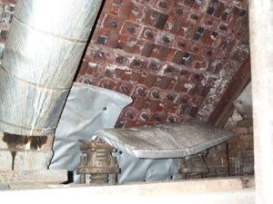
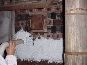
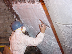
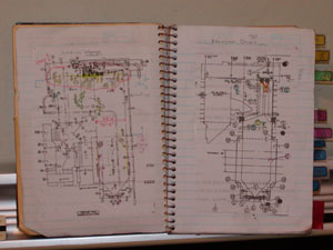
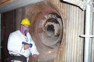
The best part of these new LNG receiving terminals is that all will need lots of mechanical insulation. So what gets insulated on a LNG-receiving terminal? Keep in mind that these terminals are receiving LNG at cryogenic temperatures, below minus 260 degrees F, and this requires considerable thickness to prevent frost formation on the surfaces. The tanks are typically insulated with a large amount of expanded perlite, amounting to about $500,000 of perlite material per tank, poured into an annular space of a stainless steel, double walled tank, with about $500,000 of craft labor per tank (see drawing at bottom left on page 22). Typically, there are two to three tanks per LNG receiving terminal, which can store about 5.5 to 6.0 bcf of NG (these volumes are in terms of the LNG as usable NG, not as a liquid). Then, there’s lots of piping, which typically gets insulated with a cellular insulation, either cellular glass or polyurethane covered with an extremely durable, vapor resistant rubber jacketing. That piping insulation may represent $3 million to $4 million of insulation material and labor per two to three tank terminal, depending on the distance between the tanks and the off loading terminal. With assistance from an expert in insulating LNG facilities, I predicted that the tanks’ insulation and the piping insulation add up to approximately $10 million of insulation opportunity per new LNG receiving terminal. That, in turn, works out to about $1.75 million per bcf of NG storage capacity.

Chicago Bridge & Iron’s Web page describes the tank insulation:

"Sidewall insulation is provided by perlite expanded and installed under CB&I specifications. Perlite is an inorganic, nonflammable, lightweight insulation produced from special volcanic rocks. The volcanic rock or ore is finely ground and then expanded in furnaces operating at about 2,100 degrees F. The perlite is normally expanded in a field operated furnace and placed in the insulation space while still hot. This method minimizes moisture in the insulation. It also minimizes breakdown of the perlite particles, since they are handled only once after expansion. The welded steel plate outer shell provides both containment and vapor protection for the perlite insulation.

The insulation closure is a lap welded steel plate between the inner tank roof and the outer shell. The outer shell is entirely butt welded together and fillet welded to the outer steel bottom. The outer lap welded tank bottom furnishes a positive bottom seal for the shell insulation and a positive vapor barrier for the load-bearing bottom insulation."

Based on existing applications for construction permits, I then estimated that there’s an upcoming insulation market potential (M&L) of $125MM to $140MM in North America for new LNG receiving terminals. Although not known for sure, it’s reasonable to assume that after approval, these will come on line between 2005 and 2009, a five year span. Based on these values, then the mechanical insulation industry could see an opportunity in the range of $25 MM and $28 MM per year in those five years. Again, while not really a huge opportunity, there’s certain to be much more to follow since the demand for NG in North America has exceeded supply and that gap, between supply and demand, be made up by imported LNG. To accept LNG, there must be LNG receiving terminals.

Incidentally, there are huge NG-reserves in Russia and several countries in the Middle East. Worldwide, there is plenty of supply. The U.S. simply needs to get it here. To do so, we will need many new LNG-receiving terminals.

Increased Costs of Manufacturing Insulation

The flip side of the increased demand for thermal insulation, caused by higher NG prices is that some types of insulation will cost more to manufacture. This is because some types are energy intensive to manufacture and some even require petrochemical feedstock.

For example, there was an industry survey conducted in the 1994-98 period of fibrous glass wool manufacturing. This survey concluded that of all the energy used, 72 percent was from electricity energy use (at the electric power plants), 25 percent from NG, and 3 percent from other fuels. If we assume a 25 percent conversion and transmission efficiency for the electricity and 80 percent combustion efficiency for the NG, the amount of energy used at the plant from each type is about equal. If I assume that the energy cost used to manufacture each pound of fibrous glass wool in that time period was $0.12, then an increase in the NG price of 57 percent and an increase in the electrical energy cost of 15 percent would increase the energy cost of making the fibrous glass wool by 1/3, to about $0.16 per pound. Over time, this may increase the sale prices of fibrous glass wool for manufacturers.

To the best that I can determine, organic cellular insulation materials, such as polystyrene, phenolic foam, and polyisocyanurate use petrochemical feedstocks. None use NG as the chemical feedstock. However, as NG prices increase, the price of crude oil follows, and vice versa, since the costs of different fuels affect one another (as shown earlier in this article). Hence, the long-term affect will be to increase the manufacturing costs of organic cellular insulation materials as well.

What Can We Do Now?

As people representing the mechanical insulation industry or as people who are responsible for energy use at an industrial facility, you should be preparing for a new era of high NG prices and of high-energy prices in general. Everyone reading this article should become a Certified Energy Appraiser, per NIA’s IEAP, if you have not already done it, so you can intelligently help customers or others at your industrial facility determine optimum insulation thicknesses. You should also be conversant in the language of costs of energy and energy conservation. In short, you should be an energy conservation expert.

For those in the mechanical insulation industry, you should be knowledgeable about the insulation requirements at a new, coal-fired electric generating station with a state of the art Air Quality Control System. I would recommend that you become knowledgeable about insulating LNG tanks and cryogenic piping so you are prepared for the emerging LNG receiving terminal opportunity. Finally, if you are an insulation manufacturer and use NG for process heat, I would recommend that you study your process carefully to determine if there are steps you can take to make your process more energy efficient.

For those prepared for the future, the future is yours.

Figure 1

Estimated construction costs in dollars per kilowatt of generating capacity for NG-fired turbine generators, coal-fired generators, nuclear plants (per the Nuclear Energy Institute) and nuclear plants per the Congressional Budget Office predictions.

Figure 2

Average Natural Gas Prices Since 1990

Figure 3

Extensive duct work such as this on Selective Catalytic Reducers, used to take out polluting nitrogen oxide gasses, needs to be thermally insulated.

Figure 4

Huge fans such as this one at SCR also need to be thermally insulated. This example has been insulated and is ready for operation.

Figure 5

Steam generators and main steam piping at a Westinghouse Pressurized Water Reactor, constructed in the early 1980s, are insulated with pre-engineered, pre-fabricated removable/reusable thermal insulation system, including stainless steel lagging. New nuclear plant construction would offer significant opportunity to the mechanical insulation industry.

Figure 6

Annual electricity production costs by fuel type. Data provided by the Nuclear Energy Institute.

Figure 7

Double Wall Steel Tank. Drawing courtesy of Chicago Bridge & Iron, Inc.

Don’t consider insulation a ‘cost’! When properly done, the insulation of your facility doesn’t add cost to the product the facility produces. It saves operating expenses, thus allowing the owner/manufacturer to become more competitive in the market. An insulation system can actually pay itself back and then continue to earn savings of energy during operation. This can be translated directly to increased efficiencies in the plant, a lowering of expenses, and potentially an increase in market share with a gain on profits earned.

Since the beginning of time, insulation in one form or another has been a part of everyone’s lives. The basic idea of keeping something hot or cold has evolved into the need to conserve energy, protect personnel, reduce operating costs and reduce emissions; thus becoming a very important part of all construction projects. Yet, we often see insulation as one of the project line items where corners are cut.

Trying to digest all of the milestones that the insulation industry has reached is quite a task. The emergence of new and improved insulation materials and products to protect the insulation is something that our entire industry strives toward. It is something for which we all can be proud. When so many materials meet the majority of the criteria of consideration for installation, the difficult task is determining not what type of insulation could be used, but what type of insulation should be used in a specific application. With rising energy costs and the need to reduce energy and emissions, a properly insulated system has never been more important.

How can this be done correctly? Insulation manufacturers, fabricators, contractors and distributors have all become more involved with the selection of materials for a specific project. We have the responsibility to assist in helping make the correct choices in all aspects of the insulation selection and application process. Being involved means being accountable. It means becoming aware and understanding a lot of hidden details that are sometimes not so obvious, but are very important to the efficient operating of an insulation system.

Materials

The term "high temperature market" means different things to different people. You may be surprised to find that 80 percent to 90 percent of the above ambient operating systems, whether commercial or industrial, operate at 300 degrees Fahrenheit (F) or below. And it may be of interest to note that for example, only about 20 percent of the piping in a power plant may exceed 350 degrees F. For the purpose of this article, let’s assume that high temperature can refer to pipe operating temperatures to 450 degrees F. Above 450 degrees, many different considerations must be examined that will not be part of this article. The most common pipe operating in the above ambient range to 450 degrees F is steam and process piping. These are primarily found in the industrial market, such as chemical, petrochemical, pharmaceutical, power and refining.

Fiberglass, mineral wool, calcium silicate, ceramic fiber, perlite, cellular glass, removable covers and more recently, high temperature polyisocyanurate, all state that their maximum operating temperatures are good to 450 degrees F, or above. Preformed or fabricated, these insulation materials are readily available. But what other factors should be considered for hot applications today?

System Design-Avoidable Mistakes

It sometimes seems that insulation is an afterthought. Contributing factors to this may be because the insulator is one of the last trades on the project, or that on a new construction project the line item cost associated with the insulation system is a small part of the total project.

As an industry it’s critical that we promote involvement with owners and their engineering and design firms at the very beginning of the process if the insulation system is to function properly. Before an insulation material and jacketing system can be chosen, many parameters must be considered. Common problems associated with failed insulation could be avoided if the substrate could be designed to allow for the proper insulation application.

Too often we run into obstacles in the field that end up jeopardizing the insulator’s ability to properly insulate the system. What job sites have you walked through and found the following:

  • Pipes that aren’t spaced far enough apart and don’t allow for the correct insulation thickness to be installed, nor enough room to work and provide a good installation of the insulation.

  • Flanges, valves, elbows and other items installed too close together, making it impossible to properly insulate.

  • The use of valves that don’t have extended bonnets on them to allow for the correct insulation thickness under the valve handle or allow for maintenance of the valve.

  • I beams, braces, brackets and other items coming in contact with the pipe, causing a thermal short.

  • Gauges, pipes, and man-way doors installed too close to the vessel or equipment, making it impossible to insulate around or above.

  • Improper type of pipe support used.

  • Pipes not primed before insulation is installed because it was never specified.

Are these items pipe system design problems, pipe installation problems or a combination? The reality of most construction projects is that while the best (or worst) of design and drawings may be provided to the general, and thus to the mechanical contractor; many projects require changes in the field. This is where good communication with the owner by the engineer to the general to the mechanical is imperative.

Involvement that includes the insulation contractor may facilitate proper installation.

Material Selection

Criteria for selecting insulation material should include the reason for insulating. In the high temperature market, the primary reason for insulating a process line is process control. Insulation may be extremely critical to the process. For example, some processes may only allow for a minimal temperature fluctuation. Erratic performance of the insulation may be extremely costly to the owner because the process was compromised.

Most other piping is insulated to protect personnel or to provide an acceptable heat loss.

Once the lines to be insulated have been determined and the ultimate goal of the insulation installation is understood, it’s important to take time and review the material and jacket systems that are being chosen for a project. Whether it’s an engineer starting to design a project, an end user trying to determine what he wants or a salesperson trying to sell an insulation material, the technical information should be reviewed thoroughly.

Each manufacturer publishes test data for the product it makes. They typically list physical properties such as thermal conductivity, compressive strength, density, temperature range and flame and smoke development. Each characteristic has a direct bearing on the insulation product’s ability to perform properly during operation of a given process or application at its service temperature. It’s quite an undertaking and almost impossible to directly compare all the materials listed earlier.

The testing organization ASTM had the daunting task of developing methods to test materials. As each of the materials are so different in composition, i.e., some fibrous, some rigid, some cellular, etc., in many instances, ASTM had to develop completely different tests, or different methods within a given test, for the same physical property because of differences between types of materials. The following are several examples of which you may or may not be aware:

In the instance of identifying the actual compressive strength characteristic of a product, ASTM has a different test method to measure a fibrous material, a different method for a cellular glass, cal-sil, etc. Each product has a compressive strength, however, none of the materials can be judged by one encompassing test.

Many ASTM tests contain several methods of testing within the test for a specific physical characteristic. In the example of water absorption, there are six methods within, all identified by one main test number. It’s of interest to note that one product sample, cut into six pieces and exposed to each six test methods, will not yield the same result.

In the past, people involved with industrial applications have not been as concerned as those involved with commercial installations in regard to the flame and smoke rating of a product. However, this has been changing over the years as plants continue to improve all safety aspects of their facility. Many products with a 25/50 rating at 1 inch thick doesn’t meet the 25/50 rating at a greater thickness, as in two layers of 1 inch each on a pipe. It’s important to network with the manufacturer regarding your materials of choice to identify the flame and smoke rating for the specified thickness of insulation required of the project.

Calculating thickness for a specified heat loss or surface temperature requires comparison of thermal conductivity of the insulation. Most ASTM test methods are based on an oven -dried sample tested at 75ºF mean temperature. What is important to know when designing the system, is the K Factor at the ‘operating’ temperature. It will be different than the published value.

In addition, it’s important to find out what happens to the insulation product at the elevated operating temperature for all of its physical properties. There are two ASTM tests that measure a host of physical characteristics of the product, 1) while in-service at higher temperatures and 2) after it has been in-service for a specified length of time. These two tests identify the insulation’s ability to perform at in-service temperatures. It’s interesting to note that most insulation materials perform differently compared to their data sheets, all properties at 75 degrees F mean, when compared to system operating temperatures. This isn’t a bad thing. These tests are only provided to increase awareness. During the design phase, identifying and addressing potential problems, such as shrinkage or warping, allows the engineer to build safety factors into the system such as double layer applications and expansion/contraction joints to provide a system that’s not doomed from the start.

Couple the differences of testing and test methods with the fact that manufacturers don’t have a standard listing of test results to report on their data sheets and one realizes that real comparison requires a good understanding of products and testing methods and the ability to read between the lines. Analyze how all of this information effects the application as well as how it changes when applied to the temperature of the system being insulated.

Fabrication of High Temperature Materials

Fabrication plays an important role in application and function of an insulation system. From the proper fabrication of elbows, flanges, valves and pipe supports, to the manufacture of insulation for large diameter pipe or small vessels. Attention to proper miter spacing ensures a proper fit in the system; both in closure around the pipe and/or fittings inside of metal covers.

Careful attention must be taken to all details of the fabrication process, including that of meeting exacting tolerances, in order to maintain the integrity if the insulation. Once again adhesives that glue the materials together are very important. Compatibility with the insulation as well as attention to flammability with the system must be considered.

For example, cellular glass is often glued together to make fittings, valve covers and other components. There are two basic means to adhere the cellular glass sections together: hot asphalt or gypsum cement. Both products have their own limitations. The cement shouldn’t be used on a cold system unless liquid nitrogen, and the asphalt can soften at 250 to 300+ ºF. If asphalt is used to adhere insulation miter sections together to make a fitting for a system that’s operating at 450ºF or above, the system will fail because the operating temperature is too hot and will cause the asphalt to melt. At the higher temperatures, the gypsum cement should be applied.

Another consideration when fabricating fittings of fibrous glass is the adhesives used to glue mitered fittings. The end service temperature isn’t always known. Adhesives that work well at lower temperatures aren’t advised at higher service temperatures. If the adhesives aren’t suited to the operating temperature, a flashing of the adhesive may occur; expelling smoke to the atmosphere and/or subsequently, the glue evaporates and the insulation falls away from the pipe. This provides another thermal short in the system, increasing energy expense and usually provides another location for water ingress.

Altering the insulation structure can have important implications. Most fibrous pipe insulation fibers wrap the pipe, i.e., the insulation runs parallel to the pipe or substrate. These parallel fibers create air gaps that improve the insulation’s thermal properties. If the fibers are cut and then installed perpendicular to the pipe it will not function as efficiently, as there is now a flow of air directly away from the pipe.

Compatible Components

Just as important as the insulation choice is to the project, the use of accessory items is to the insulation. Everything must align and mesh together to perform properly. Coatings, adhesive sealants, and claddings all must be compatible with each other and the operating conditions of the system. They must be able to hold up to the same conditions as the insulation. Each one should be reviewed and carefully assessed. If one of them fails to perform properly it will jeopardize the integrity of the total installation.

While this is an article on insulation materials in high temperature service, not only insulation and cladding can be considered. This must be coupled with the expansion of the pipe/vessel at the service temperature. Coefficients of expansion or contraction of the insulation material at the service temperature must be known. Most insulation products will shrink with heat; while the pipe expands with heat. Properly installed expansion/contraction joints and supports are a must. In addition, double layer insulation can help alleviate bare or hot spots between insulation sections.

Final Design Considerations

As the No. 1 enemy of any insulation system, whether hot or cold, is water; all choices for the system must be reviewed to make sure that the system is breathable, yet water-tight. Additional lines of defense against water should be incorporated into the total design.

It’s a misnomer that water can’t be found in the insulation of a hot service line. Water ingress can be noted under improperly installed or maintained jacket laps, improper spacing of jacket ends, at fittings, flanges, valves and other areas. As we are discussing high temperature lines of pipe to 450 degrees F you may note that through the thickness of the insulation, heat is dissipated to the surface of the insulation. To meet minimum surface temperatures of personnel protection; approximately 110 degrees F, the thickness of insulation will experience a temperature gradient from 450ºF to 212ºF, which is below that of steam, to 110ºF at the surface. The thickness of insulation that can be identified from 212ºF to 110ºF at the surface, is where water can be retained in the insulation.

Left in operation, yes, this portion can be dried, but at what expense? With the next rain, water will enter the system. The resulting expense isn’t only an increase in energy required to dry the system, but the added danger of a raised surface temperature. Remember, water is a conductor, not an insulator. The surface temperature may now exceed what is safe for personnel. And, as systems are continually taken out of service for maintenance, impurities from the atmosphere will travel via water through the insulation to the pipe surface layering salt and other corrosive elements under the insulation. Corrosion under insulation is a large destroyer of the expensive piping substrate and a huge expense to the owner. Continual maintenance is essential and a proper piping primer for the operation temperature applied to the pipe will help increase the service life of the pipe.

Positive Payback

Insulation is the only expenditure that the owner incurs that actually earns him a payback. When reviewing and comparing potential installation choices, the lowest price at installation isn’t always the most economic choice. Adequate insulation thickness, such as design for a minimal heat loss as opposed to design for thickness that will protect personnel (i.e. usually less thickness), can reap the owner instant rewards as well as continual rewards over the life of the installation. Most insulation manufacturers are able to provide an energy analysis and a return on the owners investment in insulation based on the design criteria and current energy costs.

The key is coordination. Insulation manufacturers, fabricators, distributors, insulation contractors, mechanical contractors and designers/engineers must educate the owners about the benefits of a system that can help them be more competitive in their marketplace. We all share in the responsibility of working together throughout the entire insulation process. It’s the expertise and the experience of everyone in the industry that can help insure that the insulation system(s) can be properly designed, installed and maintained.

A Serious Problem: In the last 10 years more than 28,000 insulation workers sustained injuries involving days away from work. Forty-six of them were injured fatally.

While the number of injury cases has declined to slightly less than 2,000 per year, the number of days spent away from work, per case, has increased steadily. In 2001, an average of 10 days of work were missed per injury. These diverging indicators raise an interesting question that warrants further investigation-why is it that we are seeing fewer injuries overall, yet they are significantly more serious? Even more disturbing, during the last 10 years the number of fatalities has also trended upward.

For the insulation industry, this is only part of the story. These numbers don’t include the injuries and fatalities that occur in the factories that manufacture insulation materials, at the fabrication shops, in the distribution warehouses or to delivery persons or salesmen driving to an appointment. Also, these numbers don’t include injuries and fatalities to insulation workers that are reported as specialty contractor, general and residential construction, HVAC, or building services worker injuries. And, they don’t include less severe "medical treatment" injuries and "first aid cases" that involve pain and suffering, but not days away from work.

Getting the full picture for the industry is a difficult task because all segments of the industry are not neatly reported in one category and associated work hours aren’t readily available for analyzing.

Nevertheless, we shouldn’t waste a moment worrying about the composition of the numbers as long as there is even a single drop of blood being spilled. Regardless of how the numbers are tallied, even if they totaled just one, it’s one too many. This is a serious problem that deserves the attention of everyone in the industry.

Achieving "zero injuries" in the workplace is the only acceptable goal.

"Caring is not enough. Caring is not nearly enough."

"Caring is not enough. Caring is not nearly enough." Those are the words of Paul H. O’Neill as he spoke about his 13 years as chief executive officer of the aluminum manufacturing company, Alcoa. O’Neill was talking about what it takes to achieve "zero injuries" in the workplace.

O’Neill knows what he is talking about. In 1988, when he became Alcoa’s CEO, the company’s lost workday case rate was 1.86; each year almost two out of every 100 employees were getting hurt seriously enough to miss work.

On his first day of work he met with his corporate safety director. O’Neill told him, "Beginning today, the goal for Alcoa is that no one would ever be hurt at work, not just lost workday cases, but no scratches, no first aid, nothing."

Looking back at his experience, O’Neill said, "Now, if leadership was just about giving orders and getting responses, a year later Alcoa’s rate would have gone to zero. Well, it didn’t go to zero. Why is that? Believe me, it’s not because I wasn’t paying attention to the issue and talking about it every place I went every day."

Not long after O’Neill took the helm, an Alcoa employee was fatally injured. The deceased employee was 18 years old, with three months of service, leaving behind a pregnant widow. He had jumped over a barrier to clear a jam on a piece of moving equipment in an attempt to keep production running.

O’Neill assembled his management team and told them, "We killed him."

O’Neill admitted that his management team hated him for saying that and he hated saying it. But he felt the strong words were necessary to get the message of management accountability across to his team. Before that, O’Neill said, "People would get all emotional about an accident, and they thought that was all they needed to do. Caring isn’t enough. Caring is not nearly enough."

When O’Neill left in 2001 to become U.S. Secretary of the Treasury, Alcoa’s lost workday case rate was 0.14. That’s an order of magnitude change over his tenure. By comparison, the 2001 lost workday case rate for insulation workers was 3.45, or 24 times worse than Alcoa’s rate.

The Case for Safety

Nobody wakes up in the morning and says, "Honey, we have a new objective at work to reduce our Total Recordable Injuries to 1.0, and I volunteered to help the company meet its goal by being the guy that gets hurt. Will you meet me at the hospital around 3 p.m?" Nobody plans to get hurt, and yet injuries occur.

Take a minute and write down the three most important things in your life. What were they? Chances are they included faith, family, friends, health, or a hobby. Where on your list does it say making sure we install 1,000 feet of pipe covering today or making the company just one more dollar? Safety is personal! It’s not about company objectives or mandatory requirements. It’s about being there, fully able to enjoy the things that really matter to us. Every employee has an obligation to themselves and their family to take personal responsibility for their safety.

And, is it any different for those who work with you and for you?

Every owner, manager, supervisor, foreman and worker in the construction industry and insulation trade would do well to reflect on the leadership principles of Paul O’Neill. You are accountable for the safety of those that work for you and with you!

This issue transcends union, non-union and merit shops, from the president of the company down to the insulation helper on the job. The goal for workplace safety should be "not even a scratch." Everyone goes home tonight a little bit better off for having worked today than when they arrived this morning. And it’s going to take a lot more than just caring to make it a reality.

General Gordon Sullivan, who developed the plans for the "new" Army after the end of the Cold War, wrote a book called "Hope is Not a Method." We can’t achieve an injury-free workplace by just caring or hoping. So what is it going to take?

"Making Zero Accidents a Reality"

In the early 1990s the Construction Industry Institute (CII) established a "Making Zero Accidents a Reality" project team to find out what it takes to eliminate worker injuries in the construction and maintenance industries workplace. CII, based in Austin Texas, is a consortium of leading owners, contractors, suppliers, and academia who are interested in improving the safety, quality, schedule, and cost-effectiveness of its members through research and implementation support.

The central tenet of the project team is the belief that "zero injuries" is achievable. Their first research findings, which were reported in 1993, found that it just wasn’t possible, but some companies were indeed achieving "zero injuries." Their goal was to understand what techniques are most effective in eliminating injuries in the workplace.

Last year, as a follow up to their initial efforts, the task force revisited their research. In February 2003, they released their latest findings. The CII and Project Team 160, under the leadership of John Mathis from Bechtel Corporation, were more than happy to share their findings with the readers of Insulation Outlook magazine.

The Study

According to Project Team 160 member P. D. Frey of Austin Industries, the latest "Zero Accident Study" used two approaches to identify practices that have significantly lowered recordable injury rates.

They did a survey of the ENR 400 largest construction companies in the United States. Of the 400 surveys sent out, 106 responses were received.

They also studied and conducted extensive interviews at 38 construction projects covering a wide geographical area with project values between $50 million and $600 million. These included projects in the petrochemical, industrial, public works, transportation, hotel-casino, and commercial industries sectors. Of the 38 projects studied, four had achieved "zero injuries."

The most recent update focused on turnarounds and shutdowns. This occurs when a manufacturing facility is shut down to allow the necessary work to be done. The facility may be a power plant, chemical processing, pulp or paper mill, refinery or any other kind of manufacturing facility. Needless to say, if your plant isn’t operating you aren’t making money and the time available to complete all work is at a premium. The emphasis is on getting work done fast.

Because a lot of insulation work is done on a project basis with tight deadlines, the findings of this study are relevant to the insulation trade.

The original study in 1993 identified five "high-impact zero injury techniques" that have been used to significantly lower or eliminate recordable injuries. In addition, the study found 170 specific safety techniques. It’s worth mentioning that no company uses all 170 techniques, but all the companies in the study use various combinations of at least 114 of the techniques.

Nine Industry Best Practices

The five Best Practices for "Making Zero Accidents a Reality," revealed in the first study, were reconfirmed in the update study and four new effective techniques were identified and added. The nine industry best practices as identified by the Construction Industry Institute are:

  • Demonstrated management commitment

  • Staffing for safety

  • Safety planning – pre-project/pre-task

  • Safety training and education

  • Worker involvement and participation

  • Recognition and rewards

  • Subcontractor management

  • Accident/incident reporting and investigation

  • Drug and alcohol testing

Demonstrated Management Commitment

While everyone should personally accept responsibility for their own safety, management can reinforce and support the safety initiative by emphasizing the importance of working safely and demonstrating their commitment. Management sets direction and leads with their words and actions. We have all heard that "actions speak louder than words."

  • Company president/senior management reviews safety performance report? No – 6.89/Yes – 0.97

  • Top management participated in investigation of recordable injuries? <50 percent - 6.89/All - 1.20

  • Frequency home office safety inspections? >Monthly – 2.63/< Bi-weekly - 1.33

The report suggests that managers, from supervisors to top-level managers, in the most effective companies are actively involved in project safety in many ways. They demonstrate their commitment through participation in field safety inspections, involvement in safety initiatives, such as: training and orientation, and accident investigations. The key, according to the study, is that top managers must be involved in worker safety at the project level to exert a strong influence on establishing the safety culture. Management’s involvement and commitment makes a big difference.

The box above, and the ones that follow, examine some of the key elements of the study and compare the different answers and their corresponding Lost Workday Case Injury Rate (LWCIR). Smaller numbers represent better results with zero as the goal. For example, in companies where the president and senior management regularly review project safety performance, the LWCIR is 0.97 versus 6.89 where they are not involved.

Staffing For Safety

A finding that was a bit of a revelation to the team members was the impact of proper staffing on safety. Many members of the team were safety professionals who have long believed in the importance of their role, but the new study identified specific techniques and quantified their impact. The Project Team felt the study findings that related to safety representatives, safety communication tools, and personal protective equipment were among the most important in the study.

  • To whom does the safety representative report? Line/Project – 2.41/Corporate/Staff – 1.38

  • Number of Workers per safety professional? >50 – 2.35/<50 - 1.33

Most of the projects had a full-time safety representative on the job site. A few of the safety representatives covered multiple, nearby sites. Generally, the safety representatives were company employees. In a few cases they were outside consultants.

All of the safety representatives participated in regular project meetings about cost, schedule and quality. The study found that safety personnel were integrated with all project functions.

Safety Planning – Pre-Project / Pre-Task

  • Does the project have a site specific safety program? No – 5.43/Yes – 1.76

  • Are pre-task meetings held? No – 2.67/Yes -1.04

  • Is safety training a line item in the budget? No – 2.63/Yes -1.38

According to the project team leader, John Mathis, the nature of construction and maintenance work is dynamic. Risk is constantly changing and it’s critical to follow the risk path. To be effective, the safety program must be relevant to the job site and one way to do that is to develop a site-specific program.

The study found that systematic front-end planning was done at almost every project in the form of pre-project and pre-task reviews. The focus is on potentially hazardous tasks, conditions and materials. The reviews identify special training and/or procedures needed to perform the work safely.

This technique improves hazard awareness and assures better employee compliance. And, where workers are involved in task safety planning, employee participation and buy-in to the safety program is increased.

Safety Training and Education

  • Every worker on site receives orientation? No – 5.72/Yes – 1.76

  • Type of safety orientation provided to workers? Informal – 3.80/Formal – 1.51

  • When are toolbox safety meetings held? Monday – 3.25/Daily – 1.01

  • When are toolbox safety meetings held? Tues, Weds or Thurs – 2.00/Daily – 1.01

  • How much monthly training do workers receive after orientation? <4 hrs - 2.79/ >4 hrs – 0.96

  • Monthly training provided to superintendents and project managers? <4 hrs - 2.00/ >4 hrs – 1.07

Workers must be knowledgeable about how to perform tasks safely. Training, in many forms, was found to be a very effective influence on safety performance.

The original study found that when it comes to safety, orientation and training are inseparable, but different. Orientation is the "safety first step" given to workers and visitors. It includes all information that a person needs to protect themselves from injury. Safety training is in-depth, more specific training about a variety of subjects and hazards.

The follow-up study established that almost all of the projects gave their workers safety training beyond the orientation, with an average of 5.3 hours/month. Weekly toolbox meetings to cover safety rules, hazards, corrective actions, and a review of injuries and near misses, were a strong component of many safety programs. It was interesting to learn that the day that the toolbox meeting is held and the frequency of meeting made a big difference.

Worker Involvement and Participation

  • Does a formal worker to worker observation program exist on the project? No – 2.82/Yes – 1.38

  • Do management and supervisory personnel receive behavior overview training? No – 2.82/Yes – 1.38

  • Are safety perception surveys conducted on the project? No – 2.82/Yes – 1.33

  • Total number of safety observations filed on the project? <100 - 1.93/ >100 – 1.01

This portion of the research focused on behavior-based observation programs and safety perception surveys. They found that over half of the projects had a formal observation program. Most were developed in-house and the remainder with the aid of consultants. Interestingly, the projects with formal behavior-based safety programs generally had better safety record keeping.

Three quarters of the projects used hourly workers to make observations to correct unsafe behavior and to reinforce good behavior. On other projects, supervisors and managers functioned as observers.

Use of worker safety perception surveys was a method employed on some projects to encourage workers to help find problem areas. The research indicated that this is a relatively new approach. Only a few companies have more than a year’s experience with perception surveys.

The study gave several examples of typical survey questions:

  • Do you feel safe on this project?

  • Do you feel comfortable bringing safety issues to someone else’s attention?

  • Do you feel the company would support you if you refused to work in an unsafe environment?

These surveys are intended to gauge the overall perception of safety by seeking input from the workers.

Recognition and Rewards

  • How often are incentives given to workers? Quarterly – 3.29/Weekly – 1.33

  • Is incentive based on zero injury objective? No – 3.29/Yes – 1.33

  • Do family members attend safety dinners? No – 2.35/Yes – 0.18

  • Does the project have a formal worker incentive program? No – 2.05/Yes – 3.20

Project Team 160 also examined the effectiveness of various approaches to incentives and rewards. Mathis says, "You can’t buy safety. You got to get to behavior. Recognition and rewards are only powerful if they result in safer behavior."

Incentives can broadly be divided into gifts and monetary rewards. Gifts, like jackets, ball caps and gift certificates were found to have an impact on safety performance, but little impact on reducing the number of injuries. Many of the projects in the research group used monetary rewards. With monetary awards the study found that people were more motivated to ensure that all safety items are highlighted and discussed, instead of risking losing the award.

The study uncovered another surprise about monetary awards that is worthy of note. It compared cumulative incentives with progressive incentives that increased non-linearly. Cumulative incentives are simple; typically some monetary amount times the hours worked that month. Progressive incentives are where the reward increases faster than the number of hours worked safely. The results showed projects that did not use progressive rewards had better safety records-LWCIR of 3.9 versus 6.8. The study found that smaller rewards, given more frequently as a separate check, were more effective.

But, the most remarkable finding in the entire study was a technique of involving the worker’s family members in safety dinners. Of all techniques reported back by the team, the projects where this technique was used had the lowest average LWCIR of 0.18! The conclusion one comes to is that workers take more ownership and are more accountable for their personal safety when the importance of workplace safety is shared directly by the company with the family and not just the worker. Better than meeting the family for the first time in the emergency room or worse, at the funeral home.

Subcontractor Management

  • Are there sanctions for subcontractor non-compliance with safety standards? No – 5.35/Yes – 1.43

  • Do all subcontractor workers attend a formal standard safety orientation? No – 5.33/Yes – 3.30

  • Subcontractors submit site-specific safety plans? No – 3.83/Yes – 1.37

  • How frequently do subcontractors hold safety meetings? Weekly – 2.45/Daily – 1.04

On large projects, like those in the CII study, many insulation contractors function as subcontractors. The average project employed 31 subcontractors and these subcontractors frequently employ hundreds of workers. The study points out that involvement of the subcontractor employees in the safety process is critical and vital to the safety performance of the project.

Accident/Incident Reporting and Investigation

  • To what extent are recordable incidents investigated by top management? <50% - 5.60/All - 2.00

  • Number of near-misses recorded on the project? >50 – 2.35/<50 - 0.57

The study emphasizes the importance of investigating the causes of all types of accidents and incidents to prevent recurrence. Investigation of an accident or incident should send a message of management’s concern for the safety of all workers on the project. They found that over three quarters of the projects investigated near misses, OSHA recordables, and lost work days cases.

The research found many different approaches to investigations. Including what is investigated, who conducts the investigation, and senior management’s role in the investigation.

Those who are able to obtain zero or near zero injury rates were found to have rigorous investigation procedures aimed at finding the real reasons and making recommendations on how to prevent recurrence rather than pinning blame.

Drug and Alcohol Testing

From the original research, drug and alcohol testing was found to have a significant impact on reducing injuries. Studies, conducted by others, also support that when random testing for drugs and alcohol is conducted, safety is profoundly improved. The most recent Project Team 160 study corroborated the original findings.

Some Final Thoughts

Other than the nuclear industry, I doubt there are any other industries that have done this extent of research on worker safety. The comparison of safety performance between the companies in these studies reveals many techniques have been used to create safer companies and workplaces. These same techniques can be used by members of the insulation community to improve worker safety.

The techniques that result in a zero-injury workplace can be learned and applied in any workplace. "Zero injuries" is achievable! It begins with every worker taking personal responsibility for their own safety. And everyone in the company and on the work site must adopt a "zero tolerance" attitude and do everything necessary to eliminate pain, suffering and loss in the workplace.

Last year, more than 1,800 insulators were injured seriously enough to miss work. We are headed in the right direction, but we can’t rest until we reach the point where, as Paul O’Neill said, "No one would ever be hurt at work, not just lost workday cases, but no scratches, no first aid, nothing."


V. Scott Pignolet wishes to express his deep appreciation to John Mathis and P. D. Frey from the Project Team 160 and Director, Ken Eickmann and the Construction Industry Institute (CII), for their cooperation and willingness to share information that can make a huge difference in the insulation workplace. For the complete study results and other ideas about how to improve safety in the workplace, visit the CII Web site at www.construction-institute.org.

There are currently no federal or state regulations governing the response to water damage events or mold remediation. However, there are numerous government-associated guidelines that have established new "community standards" for the management of these important issues. In addition, several professional/industry associations have published guidance documents for their practitioners. Unfortunately, there are differences in both the recommendations and interpretations of these guidance documents, which have led to confusion within the community being served.

Moisture control is the key issue in minimizing the potential for mold growth within buildings. Building "stewardship" during the design, construction, start-up and operation of the building can greatly minimize water issues. However, all buildings will experience water intrusion events in the form of flooding, roof, building envelope and plumbing leaks, and/or weather related intrusion. Rapid response is essential for protecting the building and occupants. Guidance documents from the American Red Cross, the Federal Emergency Management Agency (FEMA), the U.S. Environmental Protection Agency (EPA), and the Institute of Inspection, Cleaning, and Restoration provide guidance on response to water damage events, but the recommendations regarding management of wetted insulation materials vary within these documents. The range of suggested approaches for addressing moisture-impacted insulation span simple drying to immediate removal.

One of the potential consequences in failure of moisture management and response may be mold growth that will necessitate a mold remediation project. The primary recommendations for the investigation and remediation of mold growth have been developed by the American Conference of Governmental Industrial Hygienists (ACGIH), the EPA, the New York City Health Department, and the Institute of Inspection, Cleaning, and Restoration. Similarities and differences in the specific guidance regarding environmental monitoring, containment, and personal protective equipment impact the extent of the response effort.

Mycology 101

Fungi are a large group of organisms that form a kingdom of eukaryotic organisms (such as plants and animals) that have cells bound by rigid walls usually formed of chitin and glucans. There are more than 100,000 different species of fungi, and they can be found in virtually every ecological niche. The scientific study of this diverse group of organisms is called "Mycology," from the Greek words "mykes" for mushroom and "logos" for discourse.

Fungi don’t have chlorophyll, so they can’t produce food through photosynthesis as a plant can. Instead, fungi feed by absorption of nutrients from the environment. They secrete digestive enzymes to break down the material (substrate) they are growing on and then absorb the nutrients from that substrate. This process of feeding is very important to the environment, because it’s what allows the fungi to decay the large amount of plant debris that’s produced every year, which may well make the fungi one of the world’s number one recyclers. Unfortunately, fungi don’t restrict their attention to naturally occurring dead wood and leaves. Where there’s a trace of moisture, their omnipresent spores will germinate, and they will attack food, fabric, paper, paint, or almost any other kind of organic matter.

Fungi Growth Requirements

In addition to an appropriate source of nutrients, fungi need certain other environmental conditions to grow. The most important conditions are temperature and water activity.

Temperature Requirements

Fungi will grow at a wide range of temperatures, but most species grow best between 25 and 30 degrees Celsius (C) (between 77 degrees and 86 degrees Fahrenheit [F]). The lower and upper temperature limits are about 10 degrees C and 40 degrees C (between 50 degrees and 105 degrees F). However, certain "thermophilic" fungi will grow at temperatures as high as 50 degrees C (121 degrees F) in composting habitats.

Water and Water Activity

Regardless of the nutrient status of any material, whether a microorganism grows on and in that material or not depends on the availability of water in the material. Every microorganism has its own particular moisture requirements. Its growth depends on enough "free" water being available. Free water can be thought of as the absorbed water that’s not held tightly in chemical union with the material. The term used to describe the amount of free or available water is "water activity." Water activity is an important indicator of a material’s ability to support microbial growth. Theoretical limits for microbial growth lie between water activity levels of 0.65 and 1.0, with 1.0 being saturated. Practically speaking, if water activity in materials is maintained below ~0.75, microbial growth will be limited; below a water activity of 0.65, virtually no microbial growth will occur on even the most susceptible materials. The range of fungi found in indoor environments are able to grow at water activity from a range of 0.70 to 0.80, and even some as low as 0.65. Other fungi, such as Stachybotrys chartarum, are hydrophilic (water loving) and prefer water activity levels greater than 0.90, which is an extremely wet environment.

Reproduction and Spores

Reproduction is the formation of new individuals having all of the characteristics typical of the species. Two general types of reproduction are recognized for the fungi: sexual and asexual. Typically, fungi reproduce both sexually and asexually, although not necessarily at the same time. The sexual and asexual reproductive units of fungi are called spores. Fungal spores are usually enclosed in a rigid wall. Fungal spores differ from plant seeds because the spore does not contain an embryo. In general, asexual reproduction is more important because it results in the production of large numbers of individuals (Alexopoulos 1996). Asexual fungal spores include zoospores, sporangiospores, and conidia. Asexual spores are of particular importance to indoor air quality because they are the reproductive units for species of Cladosporium, Aspergillus, Penicillium, Ulocladium, Alternaria, Fusarium, Trichoderma and Stachybotrys, to name several.

Spores permit rapid dispersal and a kind of scattershot saturation of the biosphere-fungal spores are everywhere. Spores are dispersed by wind, by water or by animal vectors, and they can often survive long periods, sometimes even years, of unfavorable conditions such as freezing, starvation or desiccation. This durability is an important characteristic for the survival of the species, but it also means that spores will remain viable in environment for extended periods. This durability is associated with the mold growth that can occur in buildings that experience water infiltration. That is, spores will contaminate all surfaces in a building and then just "wait" until conditions (water) become right for them to germinate and grow.

Mold Growth Within Buildings

Molds have always grown within our buildings. However, there are increasing numbers of reported health effects associated with continued or extensive mold growth. These reported problems are typically associated with extreme weather events (flood, hurricanes, tornados) or chronic water problems in the building. Previously, most reported mold problems in buildings were associated with issues in the heating, ventilation, and air-conditioning (HVAC) system. We now recognize significant mold growth problems on many other building materials and components within buildings. Remember that most of the environmental conditions necessary to support mold growth already exist in buildings; building materials are already "seeded" with mold spores from natural infiltration, the temperature inside buildings is generally within the optimal range for mold growth, and many building materials either serve as or are contaminated with appropriate nutritive sources for the fungi.

Water Intrusion

Again, water is the limiting factor for mold growth within or on buildings and building materials. Thus, moisture control is the key issue in minimizing the potential for mold growth. Building "stewardship" during the design, construction, and operation of the building can greatly minimize water issues in buildings. However, all buildings will experience water intrusion events in the form of flooding, roof, building envelope and plumbing leaks, and/or weather related intrusion. Additional factors that that introduce water into the building system include improperly sized or operated HVAC systems and occupant activities. Condensation associated with building pressurization problems and inadequate or improperly installed insulation is also a significant source of water in buildings.

Responding to Water Intrusion Events

Rapid response is essential to protecting the building and occupants, because quick drying of building materials is an important mitigation effort that can prevent or limit mold growth in a building. Guidance documents from the American Red Cross, FEMA, the EPA, and the Institute of Inspection, Cleaning, and Restoration Certification (IICRC) provide guidance on response to water damage events, but the recommendations regarding management of wetted insulation materials may vary between these documents. For example, all of these guidelines recommend that wetted cellulose insulation be removed and replaced. However, for fiber glass batt insulation, the American Red Cross and IICRC documents state that the batts may be dried and reused, while both the EPA and FEMA documents recommend removal and disposal. Perhaps more importantly, these guidance documents don’t address the full array of different building materials or insulation products. For example, rigid insulation products aren’t specifically addressed in the EPA or IICRC documents, while the American Red Cross document states "Styrofoam survives best and may only need to be hosed off" and is silent on the other types of rigid insulation.

This conflicting and incomplete guidance is somewhat problematic. The lack of specific recommendations for certain types of insulation products can result in inappropriate management of wetted materials, because the response will be based on the experience and/or bias of the response personnel. Alternatively, certain materials aren’t specifically addressed in the guidance documents, which may lead some to incorrectly conclude that the material isn’t affected/impacted by a water event. An additional concern is that many of the recommendations seem to be based on the performance of the insulation material alone, and not on how the insulation may impact the performance/drying of the associated building elements. For example, does the insulation act as a "vapor barrier" to prevent release of water for a wetted wall cavity?

Until these informational voids are addressed, appropriate response to water intrusion events is compromised. It’s important that the guidance documents provide complete, factual, and consistent recommendations. Therefore, it would seem appropriate for the insulation industry to partner with the mitigation industry/agencies to develop meaningful information regarding the drying and reuse of the full array of insulation products.

Mold Remediation

One of the potential consequences of failures in moisture management and response may be mold growth that will necessitate a mold remediation project. There are currently no state or federal regulations governing mold remediation. However, there are numerous non-regulatory guidelines that serve as a reference for potential mold and moisture remediators. The most frequently cited guidance documents for the investigation and remediation of mold growth have been developed by the ACGIH, the EPA, the New York City Health Department, and IICRC. These guidelines provide a hierarchal approach to remediation, which is based on the extent of water/mold-impacted materials. That is, the more visible mold growth that is present, the more rigorous the control measures required for remediation. Similarities and differences in the specific guidance regarding environmental monitoring, containment, and personal protective equipment impact the extent of the response effort.

This stratified approach makes sense when one considers that the primary focus of these documents is protection of the health of occupants and cleanup personnel. Most of the guidelines also focus on correcting the water problem, drying the building and building materials, and complete removal of all mold growth and residual contamination.

As was the case in the water response guidelines, insulation products are incompletely addressed in the mold remediation recommendations. While the New York City Department of Health guidelines recommend that porous materials such as ceiling tiles and insulation with visible mold growth be removed and discarded, most of the other documents don’t specifically define remediation methods for insulation products with mold growth. General expectations can be inferred from the recommendation that porous materials typically can’t be cleaned and should be removed and discarded, while non-porous materials can be cleaned and reused. Unfortunately, this guidance doesn’t account for the differences in "porosity," resistance to mold growth, and other properties specific to the various insulation materials. Therefore, mistakes in judgment can be made that will result in either wasted resources (unnecessary removal and disposal of "safe" products) or unsafe conditions (mold contaminated products being reused). Again, it seems appropriate that the insulation industry partner with the agencies responsible for these guidance documents to assure complete, factual, and consistent information/recommendation.

Prevention Versus Mitigation or Remediation

Preventing water and mold problems should be easy. We do know how to design buildings, select appropriate products, appropriately manage the construction process, and effectively operate and maintain our buildings. However; we frequently fail to coordinate and integrate these processes. The result is wet buildings with mold problems. Therefore, it’s imperative that insulation manufactures, specifiers, and installers collaborate to optimize the performance of their products. Education and communication are at the core of this collaboration. Manufacturers must provide science-based information regarding the indications and limitations for the products. In particular, how the products perform in relation to other building materials and construction types.

Factual information of how the product performs when wet is also important. Specifically, it’s important to know how/if the material can be dried, how the "installed" material may impact the drying of other adjacent building materials, and how wetting will impact the long-term performance of the material.

Finally, clear recommendations on remediation methods for all insulation materials should be developed. It’s essential to know if and how a product can be cleaned for effective remediation of mold growth.

Conclusion

One certainty related to construction is that water will enter our buildings. The water can result from poor design features, poor stewardship during construction, construction defects, weather events, and the stresses of occupancy. Failure to effectively manage water in our buildings can result in mold growth and degradation of the indoor environment. A key factor in minimizing the impact of water events is the availability of products that perform well within the design and construction constraints of the building. Prevention is the preferred method for protecting our buildings. Prevention involves good construction processes that keep rain and ground water out, allows the building to dry if it gets wet. Insulation systems must contribute to these objectives by enhancing the barriers to water infiltration and facilitating the release of incidental water. In addition, insulation products should be compatible with mitigation strategies that may be required when our buildings get wet. Finally, insulation products should be resistant to mold growth to minimize the impact of long-term or unrecognized water problems.

Mistake Number 8: Driving Out All Fear

"Drive out fear."-W. Edwards Deming

What Peter Drucker did for how we manage our business, Dr. Edwards Deming did for how well we make our products.

Deming came to public prominence late in his life. Born at the start of the 20th century, he was educated in mathematics and physics. He graduated at the height of the Great Depression, managing to find work in the United States Department of Agriculture. In the late 1930s, he joined the Census Bureau, where his training in statistical sampling methods proved useful in the 1940 Census.

Then things started getting interesting. With a world war going on, Deming put his knowledge about statistical sampling methods on the factory floor, helping to dramatically improve the product quality of U.S. war materials. In the 1950s, he was invited to Japan to help rebuild their manufacturing sector. What worked in our factories worked just as well in theirs.

Fast forward to the 1980s, where we began to fully appreciate what the Japanese had accomplished in product quality of everything from automobiles to consumer electronics. They did that following the advice of a statistician who got his start counting cows and people. The Japanese honored Deming by naming their national quality award in his honor.

When we finally woke up to the "quality revolution" that had been taking place in the manufacturing sector, there to help us was the towering figure of W. Edwards Deming. Deming was in his 80s, but still a commanding figure, both intellectually and physically. (We still remember Deming’s photo, taken with our plant quality manager: the good doctor stood every bit of 6 foot, 8 inches.)

In his years of working with industrial clients, Deming built what many of us in the manufacturing management business would learn as his "14 Absolutes of Quality." These were the principles and practices Deming believed absolutely essential for managers to follow to achieve the highest standards of product and service quality. It was great stuff to pay attention to for us managers.

In the middle of his list of absolutes was the proviso to "Drive out fear." Deming believed that, in the campaign to improve quality, fear of getting in trouble for making defective products and reporting quality problems was a major roadblock to progress. We’re sure he had plenty of firsthand experience that led him to that conclusion.

Management can’t fix what it doesn’t know. Deming wisely concluded that the fear of reprisal from management kept many employees from reporting product quality problems. The guys out in the warehouse would rather ship a defective product and let the customer figure out there was a problem: surely, management wouldn’t fire the customer when they told them there was a problem. Of course, having the customer finding the defect was never good for sales.

If Deming’s absolute of "Drive out Fear" was right for quality improvement, why wouldn’t it be just as good for improving safety? More than a few of us thought so, and tried to apply the same concept to managing safety performance.

It sounded like a great idea. People would tell the truth during investigations and report all their near misses. All we had to do was tell them that nothing bad would happen to them if they did so. Talk about driving out fear!

However, we failed to do what Deming did, as he built up his absolutes: think critically about the implication of the concept. Deming built his absolutes over a career that spanned more than 60 years. Most of us were from the "One Minute Manager" school: we figured: "That sounds like a good idea. Let’s give it a try and see how it works."

It didn’t work nearly as well as we thought. Employees didn’t trust us in the first place not to take action when they told us the truth. The few who did were extremely disappointed in the cases where we didn’t–or couldn’t–keep our word. Sometimes what they told us had to be dealt with–including their own choice of bad behavior.

If we had thought critically about the subject of "driving out fear" as it relates to safety, our conversation might have looked like this:

Drive out fear. Fear of what? The answer is consequences. It’s the consequences that employees fear. When it comes to making a quality product, we wish they wouldn’t fear consequences: if we have a product quality problem, we’re better off knowing that than having our customers find it for us.

Are the consequences of making and shipping a defective product the same as a serious injury to our employees who make the product? The answer is no (unless the product defect causes injury to someone else). Our forklift operator breaking his leg is far worse than shipping a batch of paint that doesn’t match the color specification. The paint can always be returned.

On the other hand, if the forklift operator had a near miss incident-nearly running over someone, would we be better off knowing about it? Sure we would. What would prevent the operator from reporting that near miss?

Fear that he would get in trouble, which might happen if he admitted that he was driving way too fast and not paying attention when he nearly hit that guy in the warehouse.

So, our forklift operator makes the calculation of consequences: better to be safe (from management) and not report the near miss than run the risk of getting in trouble. "Getting in trouble" is the consequence that people fear. It keeps them from telling management what’s really going on out there.

Is that the greatest consequence that our forklift operator should fear? Give the question more than a moment of thought, and a far greater fear emerges: the fear of doing serious harm to a co-worker. How would anyone feel having to go through the rest of their life knowing they were responsible for the permanent injury–or death–of someone with whom they worked?

What should everyone who works fear the most? It’s not making a defective product, or even getting chewed out for not being careful. It’s doing something that gets him, or someone else, seriously hurt. Fearing those consequences is a good thing. It’s a fear that everyone should want to increase, not drive out.

Sure, along the way, you have to deal with people who choose fear of discipline as their principal motive. If that gets them to follow the safety rules and pay attention to what they’re doing, that’s not all bad. What motivates many of us to obey the speed limits is the thought that there just might be a cop around that next curve in the road.

The fundamental motivation to follow the safety rules and work safely should be driven by fear of what an accident would do to the life of the person who got hurt. You never want to drive out that fear.

Instead of following Deming, we should have chosen to follow the advice of Edmund Burke: "Early and provident fear is the mother of safety."

Not recognizing that truth is one of the mistakes that many of us have made.

"The difference between luck and skill are seldom apparent in the short term."-Investment Advice

Mistake Number 7: Failing to Appreciate What Managers Really Impact

The management team has gathered around the conference table in an emergency meeting. The urgent topic: what to do to stanch the rising tide of accidents and injuries?

It’s a familiar scene to any line manager who’s been out on the field for very long. Safety performance never follows a straight line. Like competitive athletics, safety performance is made up of streaks and slumps. Even places with the best safety numbers hit the occasional downdraft, leading to meetings like the one just described.

These crisis meetings are guaranteed to produce a flurry of activity, all designed to have an immediate and substantial impact on safety performance. We "round up the usual suspects." You know what they look like: send a letter urging everyone to pay more attention to what they’re doing; show up at safety meetings with the same message; call a time-out for safety; solve some specific problem that was a factor in a recent accident.

Then we sit back and hope it works.

Fortunately, it usually doesn’t take long for performance to get better. When it does, it confirms what we knew all along: get us as managers involved in the details of managing safety performance, and we’ll do it better than anyone else around. Are we good or what?

Once we’re finished fixing "the safety problem" we get back to working on all the other business problems we face every day.

If he were there to watch all this, W. Edwards Deming would be rolling on the floor, laughing. As Deming understood so well, what we witnessed was random variation. The esteemed consultant would explain the concept: everything in life has variability. When the numbers go one way, they’ll eventually go the other way. To the statisticians, the term of art is "regression to the mean." It’s the mean–the long-term trend line–that’s what’s important, not the short term fluctuations in performance.

The phenomenon has fooled us time after time. When we jump in and act, we see results; performance improves. We think we’re having an impact on performance. It has to be the direct result of our good work. Of course, all that reinforces all the wrong managerial behavior.

The truth is that we’d have seen the same result if we had gone on vacation. It’s the one of the biggest mistakes managers make managing safety performance. But it’s only half the story.

While we overstate the short-term impact of our direct involvement in pulling the strings to improve performance, we consistently under-appreciate the long-term impact of our performance as managers. That trend line that safety performance regresses to is essentially the measure of our competency as line managers.

All along, we should have been thinking about safety performance this way.

Let’s accept as a given that safety performance varies significantly from one industry group to another. For a lot of reasons, the average performer in the plastics manufacturing business has an injury rate that’s different from construction or the oil-field service industry. Within each industry group, though, the means and method to perform the work are roughly equal; the exposure to job safety hazards is comparable.

That being the case, what separates the performance of the best and the worst performers within the industry group? It must be the collective competency of management, those who lead and manage safety performance.

It used to be said of legendary football coach Paul "Bear" Bryant that "he could take his team and beat yours; then take your team and beat his."

Of course, that’s not how most of us saw the situation. Those other guys in our peer group of companies–the one’s getting the best results–always had something going for them that we didn’t. They had safety incentives, a better workforce, people who knew they shouldn’t report injuries, or better tools and equipment. When we couldn’t explain it any other way, then they just were "luckier than we were."

Can you hear Deming laughing?

Industry group comparisons put everyone on equal footing; in the long term, luck gets canceled out. We’re left to face the fact that we’re getting exactly what we deserve: the best managers get the best performance. It’s that simple.

It’s all too common for us managers to fail to fully appreciate our impact on performance. We think it’s far too great in the short term, and we don’t recognize that, in the long term, our results speak volumes about our performance as managers.

Peter Drucker once said: "Companies don’t compete; managers compete."

It’s a huge mistake, and one of the biggest mistakes managers make managing safety performance.

Mold is probably the best known and certainly the most frequently publicized problem in indoor environments. Mold contamination cases continue to rise at alarming rates, leading to everything from finger pointing to lawsuits that demand millions of dollars in damages. These disputes can and often do envelop impact everyone involved in the design, construction, and commissioning of a building. The truth is, mold contamination cases are complicated because the causes of mold are complicated. There is no single activity, material, or precaution that you can take to prevent mold from growing in an indoor environment. Mold prevention and management begins before the first brick is laid and extend throughout the life of the building; they involve complex building systems, multiple players, and ongoing activities within the building.

Insulation’s ability to help manage temperature and moisture makes it one of the most powerful preventative tools against indoor mold growth. Correctly installed, it supports dry, temperature-controlled conditions that inhibit mold growth. Improperly installed, it can contribute to the development of mold deep within the building walls. This article examines the role of insulation systems in maintaining healthy indoor environments, common pitfalls, and best practices for selection and installation. Steps that manufacturers and installers can take to protect themselves if a mold problem does occur are also considered. While examples given don’t include an exhaustive list of insulation types or configurations, they do represent some of the most common cases, and hopefully provide a framework for selecting and installing effective insulation systems.

Understanding Insulation’s Role

To fully understand insulation’s role in maintaining mold-free buildings, it’s important to have a basic understanding of mold. In addition to a source of spores, mold requires three conditions to grow: humidity (generally relative humidity of 60 percent or more will enable growth), warm temperatures (warmer air holds more moisture than cool air), and a source of food (any biodegradable material).

What may happen in wall systems and around heating, ventilating, and air-conditioning (HVAC) systems is that warm, moist air comes in contact with cooler surfaces and condenses. The condensation and the warm indoor temperatures provide an excellent place for mold spores to germinate. As long as there’s enough moisture and the right temperature conditions, mold can grow on any surface in which there’s a food source. Even aluminum duct work, brick or stone, plastics, glass and plaster can grow mold if enough dust and other organic particles have collected on the surface.

Insulation is important because of its ability to control temperature and, by extension, moisture. Insulation is the first defense against moisture creation in a building, by preventing air from reaching dew point temperatures of surrounding air. At dew point temperatures, condensation forms, producing the moisture necessary for the development of mold. This is true both within building wall and ceiling systems and in and around HVAC systems. If insulation can effectively eliminate the source of moisture, the building is much less likely to ever have a mold problem. However, in order to serve these purposes, insulation must be properly specified, designed, and installed.

Select Proper Insulation

The first step in creating a dry, properly-functioning indoor environment is to select the best kind of insulation for a given application and location. There are numerous types of insulation available, from fiberglass to cellulose-based, from rigid to flexible. Each type is best suited for a specific use. Architects and specifiers select insulation based on their objectives, the building structure, budget, and availability. However, specifiers should add mold prevention to the long list of considerations that weigh in during the selection process. Each of the following attributes plays a role in how insulation contributes to the prevention of mold growth.

Material

Different materials are susceptible to mold growth in varying degrees. On one hand, fiberglass, a non-biodegradable material, is resistant to mold growth. On the other hand, cellulose-based insulation, made of paper materials, is the ideal food source for mold if it becomes wet. Selecting the correct insulation material for the environment and location is essential to preventing mold growth. For example, either cellulose-based or fiberglass insulation can be used for the building envelope, but the specifier should select fiberglass insulation or some other non-biodegradable material if there is any doubt that moisture may be present in the space. Cellulose-based material should be used only when the architect can be reasonably sure that a space will be kept completely dry.

Backing

The backing on insulation can exacerbate or inhibit mold growth. Some insulation is porous with no water vapor retarder ability, and others are lined with foil, paper, or other material with possible water vapor retarder ability. Non-backed insulation allows water vapor to move freely through the material. Insulation backed with vapor retarders inhibits such movement. Selecting the right type is dependent on the moisture migration dynamics of the assembly under consideration and can inhibit or be a significant contributor to a mold problem.

Insulation that lines the interior of HVAC ducts is particularly susceptible to dust accumulation and subsequent mold growth under the right moisture conditions. Large volumes of air running through ducts deposit particles on the porous surface of the insulation, providing a food source and ideal home for mold if and when moisture is present. In areas where high levels of particulate matter, dust, or dirt are likely present, specifiers should carefully select insulation. Consideration should be made to eliminate the potential for dust build up by either externally insulating ductwork or using foil faced rigid material internally. This keeps dust deposits from collecting in the material and enabling mold growth.

In some cases, backing can support rather than inhibit mold growth. Specifiers that select fiberglass insulation for wall or ceiling systems because they worry about the possibility of water intrusion may not have considered the impact of the paper backing. If fiberglass insulation with the paper backing becomes wet, mold will grow on the paper, eliminating the whole advantage of selecting a non-biodegradable based insulation. In this case, fiberglass insulation without backing may be the best choice.

Configuration

Insulation comes in as many different configurations as it does materials. Insulation should be selected in light of the area or environment in which it will be used. For example, if an area is subject to high traffic or maintenance, it’s a good idea to select rigid insulation with a durable facing to prevent damage from wear-and-tear. Insulation around ductwork can present a particular challenge. Many HVAC system components are internally lined near the fan discharge, where the insulation is subject to a lot of turbulence. In many cases, exterior insulation of the plenum isn’t possible because it would hinder easy accessibility required for maintenance. Sometimes, the boxes are lined with porous insulation, which degrades significantly over time because of frequent movement and service. Clumps of insulation eventually wear away, exposing cold surfaces and causing condensation. Although it’s more expensive, an investment in insulation packed between two layers of galvanized steel or rigid, foil-faced insulation in these areas in the immediate area of the fan discharge can prevent problems in the long-run.

Specifiers may also select uniquely-configured insulation to facilitate proper installation and ensure more complete and consistent coverage. Pre-insulated, flexible ductwork, for example, ensures that duct runs are completely and consistently insulated.

In many commercial buildings, chilled water piping is used to distribute cool water to HVAC units throughout the building. Closed-cell insulation is ideal for this application, as its solid surface is impermeable to moisture. In addition, the non-porous nature of this insulation helps prevent against the collection of dust and particles on the insulated surface.

In short, when selecting insulation, specifiers, architects, or engineers should carefully consider the environment and circumstances in which the insulation will be used in order to reduce the possibility of mold growth.

Install Correctly

If poorly installed, even the best insulation can fail miserably to fulfill its intended purpose. Once the appropriate type of insulation has been selected, installing it correctly is the next obvious, but somewhat challenging step. There are many factors to consider when installing insulation.

Insulate Completely

Insulating completely and consistently is the first rule of correct installation. Even small spaces that are left uninsulated can result in major mold problems. This is a common pitfall when it comes to insulating HVAC ductwork and chilled water lines. In many cases where correct installation becomes more difficult or takes additional time, insulation is cut short at joints and other transitions to save time. It’s critical that every point along the line be insulated so as to prevent condensation. Even a little bit of condensation on a single point along the run can formulate a constant source stream of water that can drip and migrate to areas where biodegradable materials are located, such as ceiling or wall surfaces, and initiate mold growth.

Consult the Architect

The proper installation of insulation is not as simple as it may seem. This is particularly true in wall systems, where vapor retarders are often used in areas that experience extreme temperatures. The location of the vapor retarders, if needed, in wall construction belongs should be toward the warmer side of the building: it would be toward the outside of the wall in warm climates, and toward the inside of the wall in cooler climates. Some insulation is prefabricated with instructions to install it with the vapor barrier toward the inside of the wall. However, this would not be the proper configuration in warm weather climates. These incorrect instructions may be attributed to a lack of education or simply to the climate in the location where the insulation was manufactured. In any case, installers should consult an architect on the proper configuration of a wall system to ensure that the insulation is properly installed for that particular climatic region.

Consider Interrelated "Systems"

No matter how well selected and installed, insulation alone can’t prevent a mold problem. Part of what makes the construction industry so interesting and exciting is the complexity of modern buildings and the dynamics surrounding interrelated building systems. Insulation is just one of many materials and functions that works with and among other systems in a building to create optimal, comfortable indoor environments. It’s well worth the time for specifiers, installers, and maintenance professionals to consider other building systems that are immediately related to insulation and adjust them to support its functionality. This is a particularly effective strategy in existing buildings where insulation may have already been installed and replacement isn’t a feasible option. The objective here it to identify and adjust factors directly related to, although not precisely part of, the insulation systems.

Prevent Water Intrusion

In spaces where cellulose material may have been used though fiberglass may have been a better choice, it is important to take every possible precaution to ensure that the insulation isn’t exposed to water. Avoiding water intrusion is always the most basic rule of mold prevention. Water can come from many sources, some more easily controllable than others. An inspection of the exterior walls and roof can help identify potential problems before they present themselves.

When working at a new building site, it’s important to store materials properly. If insulation and other building materials are stored outdoors or in uncovered areas, they can get wet or grow mold before they are even installed.

Increase Air Filtration Efficiency

In many older buildings, ductwork was internally insulated with porous, open-faced insulation. The cost of reinsulating is prohibitive in many cases. However, building managers and maintenance professionals can help reduce the risk of mold growth in ducts by increasing the air filtration efficiency of the HVAC unit in order to reduce the amount of particulate matter and dust that flows through the ducts. This is a cost effective and relatively easy way to protect already-installed insulation.

Incorrectly Compiled Wall Systems

If you suspect a vapor retarder is installed incorrectly, consider retaining an experienced building forensics expert to identify such problems and recommend solutions to protect against material degradation and IAQ problems. In many cases, pressure relations can offset improper vapor retarders.

Protect Yourself

Even buildings with the optimal, properly installed insulation can become contaminated with mold. In many cases, building owners-both commercial and residential-will automatically assume that the product on which the mold is growing is the cause of the problem. However, insulation within a building can become contaminated with mold, even if it was optimally selected and installed. If the building was poorly designed or constructed, or if there was a plumbing leak or an extreme weather event causing flooding, then even the best insulation system couldn’t protect against mold.

There are several precautions that insulation manufacturers and installers can take to help protect themselves against potential litigation and the inevitable finger-pointing that comes with mold contamination cases.

Have Your Products Tested For Mold Resistance

Mold resistance testing determines a product’s susceptibility to mold growth. These evaluations can test the structural integrity of a product over time as mold begins to grow on it or simply the ability of a product to resist mold under a range of "normal" to high humidity conditions. Testing can help product engineers better design insulation to withstand different conditions that may be present in different buildings. In addition, a report from mold resistance testing can be kept on file to demonstrate that the insulation product resists mold under normal conditions, implying that the abnormal conditions under which mold grew weren’t the responsibility of the insulation manufacturer.

Watch For Design Problems

Another good policy is to bring up and document obvious problems with design or construction. Take these issues to the construction team to find out if they can be corrected immediately. The contractor or designer may not have spotted the problem earlier and can make arrangements to fix it now, preventing problems later. If corrections aren’t made, a record of these problems can be used to protect the insulation manufacturer or installer from misplaced blame.

Don’t Improperly Label Insulation

Manufacturers should carefully label insulation backed with materials that are typically used as a vapor barrier. Only qualified designers or architects should provide instructions on the placement of a vapor retarder in a given climate zone. Mislabeled insulation pieces may be used in court to transfer undue liability from the architect to the manufacturer or installer. Likewise, installers should carefully follow architectural plans in conjunction with preprinted instructions when installing any material.

Insulation’s Larger Role in Creating Healthy Indoor Environments

Not all indoor air quality problems stem from mold growth. With all of the discussion and controversy surrounding mold, it’s easy to be overly focused on that single issue without considering the broader goal: to ensure acceptable, comfortable indoor environments for building occupants.

Most of the time, different insulation types involve trade-offs for indoor air quality; that is to say that one aspect of the insulation may support good indoor air quality, while another may present a threat to the indoor environment. For example, as is the case with any manufactured product, insulation materials emit volatile organic compounds (VOCs) into the air. Although fiberglass insulation is resistant to mold growth, it tends to have a high chemical content and may be a source of potentially harmful emissions. These emissions can trigger symptoms ranging from uncomfortable to debilitating. In this case, insulation could have a negative net impact on the indoor environment. On the contrary, insulation made of natural, cellulose-based fibers may have relatively low emissions, but is a sure-fire mold problem if it becomes wet. Sometimes manufacturers try to prevent mold growth on cellulose-based materials by treating them with fungicide and other chemicals, which can also emit a chemical cocktail into the air. It can be challenging to make decisions in light of these trade-offs.

Over the past few years, insulation manufacturers have come under fire regarding their emissions of formaldehyde, commonly used in the binders in fiberglass insulation. Consumers and manufacturers alike became concerned about formaldehyde emissions from their products and the potential dangers presented to building occupants. In the last year, some manufacturers have taken proactive steps to ensure that their products are acceptable for indoor environments by having them GREENGUARD Indoor Air Quality Certified®. This program provides third party guidelines for emissions levels deemed acceptable for indoor environments. Specifiers can select insulation products bearing the GREENGUARD label or can ask manufacturers for emissions information on their products. By selecting a low-emitting insulation, they can reduce the extent to which insulation negatively impacts indoor air quality, ensuring their ultimate effect is net-positive. The good specifier will consider insulation’s dynamic role in supporting good indoor air quality and will select materials that support overall health, comfort, and functionality.

Much To Be Learned

There is still much to be learned about mold contamination, the health effects, and best practices for prevention. For now, players in the construction industry must contend with litigation, negative PR, and sometimes strained relationships at the construction site.

The best way to prevent problems is to stay vigilant and to ensure complete collaboration between all players. Insulation professionals, like all others, can do their best to prevent mold growth, but will ultimately be ineffective unless other players collaborate as well. The good news is that a little prevention goes a long way and ultimately helps ensure the safety and comfort of building occupants now and for years to come.

On May 16, 2003, a fire destroyed a Johns Manville (JM) plant in Defiance, Ohio. Not only did the fire devastate a building, it significantly disrupted the North American supply of fiber glass pipe and equipment insulation as well. The JM plant produced as much as 35 percent to 40 percent of pipe insulation in North America. Before the fire, it’s estimated that the industry was producing fiber glass insulation at about 85 percent to 90 percent capacity, so clearly there was no way that other manufacturers could simply step in and cover all the lost supply. This article describes the impact of the fire on the pipe insulation market, explains what manufacturers, distributors and contractors are doing and discusses some long-term implications for the industry.

How Manufacturers Are Managing

The fire’s immediate result was a shortage of insulation. The industry reacted by putting all available product and ongoing production on some form of allocation.

At JM, we quickly evaluated existing inventory, including some from Defiance that escaped damage from the fire and its suppression, to determine what products were suitable and available for shipment. We also adjusted output on the one surviving machine to produce a range of sizes most in demand. Using the one machine gives us less than 10 percent of the capacity we had before the fire, which destroyed the equivalent of 11 machines producing 3-foot insulation sections.

To some extent, other fiber glass suppliers also have "pruned" product lines. Without enough capacity to meet total demand, everyone is concentrating on making pipe insulation in the sizes that allow maximum output and that are most frequently required by contractors. For example, all suppliers have temporarily reduced or eliminated production of 1/2-inch wall insulation in certain sizes.

At JM, we responded to constricted supply by accelerating development on an alternative product and moving its introduction ahead several months. Micro-Flex™ CTS Precision V-grooved Pipe Insulation is based on the company’s Micro-Flex Pipe and Tank insulation. Precision-cutting grooves in the fiber glass makes it capable of curving easily to wrap pipes as small as six inches in diameter. This new product delivers thermal performance and insulation value comparable to the pipe insulation it is designed to replace, so its introduction allowed JM to concentrate remaining capacity on producing insulation for pipes smaller than 6 inches.

All manufacturers have sought additional supplies of fiber glass pipe insulation, largely through imports. Product is being brought in from plants in Europe, Asia and even Africa. These imports tend to be in lengths that are less familiar to North American installers. The most common is 1.2 meters–"a meter-twenty"–which is almost 12 inches longer than the 3-foot length that is commonly used in the United States. Although different in size, these products, as supplied by JM and the other major fiber glass suppliers, have similar physical properties and meet the same performance and fire safety standards as pipe insulation manufactured in the United States.

Distribution, Contracting and Engineering Implications

Some distributors have found that the shortage doesn’t threaten their business as much as they feared it would immediately following the fire. Jack Schunk, sales manager for McCormick Insulation Supply, Inc., Owings Mills, Md., admits that there has been an impact on sales, not only of insulation but accessory items as well. However, he says, "This is not as bad as we had anticipated. My perception is that things are slowly getting better. We’ve been dealing with Johns Manville for a long time, and it’s not too surprising that they have handled this so well. We may not get everything we want, but they’re trying to take care of us."

Vaughan Privett, chief executive officer of the Norfolk, Va.- based insulation contracting firm C.E. Thurston & Sons, Inc., concurs. He notes that lead times are longer and prices higher, but he believes that fiber glass pipe insulation for industrial applications is generally available.

While distributors are optimistic that they can wait out the situation, there are still disruptions in the short term. According to Erik Jensen, chief executive officer of distributor/contractor E.J. Bartells in Seattle, Wash., "This has had an impact on our business and is a major disruption to distributor relationships with vendors and customers. But we are working through it and JM has done a great job of communicating their plans."

Jim Pfister’s first reaction to news of the fire was to try to buy as much Johns Manville insulation as he could. After that, Pfister, president of the distribution and contracting firm Ludeman Insulation and Supply, Inc., of Wichita, Kan., went to other fiber glass manufacturers. He is able to buy competing insulation from another distributor, but at a higher price. The Ludeman strategy is to use existing insulation inventory to complete its own contracting projects and stock a limited amount of more expensive insulation to supply customers having immediate needs. The firm also has started bidding jobs with extra dollars allocated for insulation materials because of uncertainty about cost and productivity.

Some distributors have attempted to import foreign-made product directly. Often this material is unjacketed and differs from domestic materials in other ways, too. Distributors must verify that this independently supplied material meets all applicable thermal and fire performance tests. As Johns Manville returns to the market with significant additional production later this year, we anticipate demand for offshore materials to decline because it’s more difficult for foreign suppliers to meet the high service demands and short lead times that distributors and contractors normally require.

We have also heard reports that some distributors and contractors are being pressured to enter long-term agreements with alternate foreign and domestic suppliers in order to be assured immediate supply. We are working hard to bring new equipment on line as soon as possible to increase supply and help end this practice.

Contractors, even more than distributors, find themselves on the front lines. Their customers–mechanical and general contractors and building owners–sometimes challenge them on delays and alternative materials. Chuck Rawlings, president of the insulation contracting firm TBN Associates, Inc., Beltsville, Md., says his company and its sister business, TRA Thermatech, initiated proactive communications with customers as soon as the fire occurred so they could anticipate shortages and delays. Their strategy has been to communicate as openly as possible and work with customers on solutions in order to avoid invoking force majure. Rawlings says they have managed until now by allocating their remaining inventory and actively searching for fiber glass supply. They have a buyer working almost full time to find fiber glass insulation.

"We have dedicated a lot of time and resources to finding materials that were normally available off the shelf," Rawlings says. The result is that TBN, formerly an exclusive JM customer, now uses fiber glass from a variety of sources. "There are a whole lot of different-colored boxes around here than what we’re used to," Rawlings says. One question this raises is whether using fiber glass from different manufacturers has an impact on productivity as installers try to work with unfamiliar materials.

Alternative Materials

The shortage of preformed fiber glass pipe insulation has prompted customers to evaluate alternatives they never considered before. Bartells’ Jensen explains that demand for fiber glass was based not only on performance but also on habit, availability and price–all of which have been affected. Now distributors and their customers are willing to evaluate substitutes.

"Alternative materials are getting a lot more attention and consideration than they did in the past," he says. There are not direct substitutes–every alternative presents differences in material costs, installation productivity, physical properties, longevity, lifecycle cost and thermal and fire performance. Bartells works with contractor customers and Bartells’ own contracting division to evaluate all these factors and help resubmit specifications with alternate materials where appropriate.

Micro-Flex CTS is a fiber glass substitute that is suitable for certain applications. We have found that installers accept it for virtually all applications with pipe diameters of 24 inches and greater. We have also found that it is substituted for preformed fiber glass insulation about 50 to 75 percent of the time on pipe sizes between 18 and 24 inches. The product can be used on pipes as small as 6 inches, but the application is so new that we have not yet measured acceptance. Jack Schunk of McCormick Insulation Supply reports that, despite initial misgivings about the ease of installing this different material on smaller pipes, early feedback from his contractor customers is positive.

Another obvious alternative is to substitute 1-inch-thick fiber glass for hard-to-find 1/2-inch. Where that’s not possible, flexible foam insulations are being used on smaller pipe sizes in commercial applications such as domestic water systems. Ludeman’s Pfister has found that most engineers are willing to accept this alternative as long as the thickness is the same. Foam insulations are suitable for many commercial uses, but they shouldn’t be substituted for fiber glass in higher temperature applications. Furthermore, these materials aren’t available as preformed pipe insulation for larger pipe sizes.

Distributors carry a variety of other products that can be substituted for fiber glass in some applications. Mineral wool, polyisocyanurate and cellular glass are occasionally being substituted for fiber glass. However, these products tend to carry a higher price tag and are more difficult to install. As a result, the rate of substitution so far is fairly low, and in most cases contractors are accepting longer lead times for fiber glass instead of substituting products.

Besides shifting materials, some contractors are coping by shifting the balance of the business they do. C.E. Thurston says it is well-positioned to ride out the pipe insulation shortage because its business is diversified: they offer refractory and cold storage contracting in addition to installing pipe insulation. Ludeman Insulation and Supply is bidding more often on jobs that don’t require fiber glass pipe insulation in order to keep cash flowing during the shortage.

Rising From the Ashes

Johns Manville has a long history of commitment to the pipe insulation market, and that hasn’t changed. Within three weeks of the devastating fire, senior management authorized the first major investment in replacement capacity. Semi-automatic manufacturing equipment has been ordered and will be installed in a new facility in Phenix City, Ala. The first product should be available in November. With this capacity added to the machine already in operation, we expect to be able to supply at least 50 percent to 60 percent of the pipe insulation we were delivering before the fire.

This is a good start, but clearly still an interim solution. Within days of the fire, JM assembled a task force to work over a longer time frame to restore full capacity with fully automated, next generation equipment. Those plans are on schedule, and we expect to be offering a full line of pipe insulation in adequate quantities to meet demand as soon as practical. C.E. Thurston & Sons’ Privett is convinced that Johns Manville is committed to restoring capacity. "In talking with people from JM, I can see their enthusiasm for rebuilding," he says.

We’re not aware of plans by other manufacturers to make capital investments to increase capacity.

What’s Next?

Even with fast action by fiber glass manufacturers and distributors, many unknowns still face the industry. How soon can we return to the equilibrium that existed before the fire? When will we no longer require overseas supply? Will alternative materials, like Micro-Flex CTS, establish a permanent place in certain applications? While we don’t know the answers, we believe that JM’s commitment to and investment in this market will be instrumental in keeping fiber glass in the forefront as the insulation of choice in commercial and industrial pipe applications.