Just like the annoying little ghosts and goblins in the popular 1980s movie “Ghost Busters,” those pesky and sometimes
daunting-looking, all-shades-of-green mold and mildew can be hard to get rid of—a job for an experienced professional
with the right equipment.
A mold-remediation specialist can be a great friend to a business, helping to avoid potentially millions of dollars in
damage and restoration costs. When it comes to dealing with mold, ignorance is not bliss and “common sense is not always
common,” says Bill Begal, president of Begal Enterprises Inc., fire and water restoration specialists located in Rockville,
Maryland. Although a mold buster like Begal will be happy to help a business get back on track following an incident, he has
some advice to help businesses avoid making that urgent phone call for remediation.
Prevention Helps Keep the Fungus Away
The best tool in the fight against mold and mildew is prevention, Begal explains, and the best methods include having an
educated building maintenance crew and chief who do regular building walk-throughs and receiving regular visits by a
mold-remediation specialist.
Begal says that a weekly or bimonthly walk around the building to look for signs of trouble is worth every bit of time it
might take the building maintenance person. He explains that the building professional or crew are the people who know a
building the best. “They know how it leaks, how it breathes. They know the areas that have problems,” or, at least, they
should. Better yet, he adds, they should be given a maintenance budget to be able to handle problems as they arise, to deal
with them right away.
Begal even suggests that building personnel take pictures of the areas most likely to develop issues so that there are
before and after shots in case of a disaster or accident. Areas where mold is most likely to develop are any places where
moisture is most prevalent, like in restrooms, kitchen areas, roofs, near drainage pipes, near and around heating,
ventilating and air-conditioning (HVAC) units, etc. An industrial plant would also have to consider areas and pipes affected
by extreme heat or cold or high humidity. (For a complete checklist, see Figure 6.)
Mold specialists should be on the contact list—and a regular visitor—of every commercial or industrial building
maintenance crew manager, Begal emphasizes. Many restoration technicians do not know what to do. Following an incident, he
explains, “It takes knowledge and cooperation between the building staff and the technicians. I want an opportunity to walk
the building when the building is in its normal environment, not only after a disaster.”
The best complement to prevention is education. As the saying goes, “knowing is half the battle,” and that remains true
when it comes to knowing the six main ingredients for growing mold (see Figure 5). Once a mold spore enters an area, it needs
a host—any material that is cellulose. Then, it will grow and spread where there is a lack of light, lack of airflow and
circulation, proper temperature—the warmer the better—and moisture or a supply of water, including humidity.
Begal explains that an uneducated maintenance professional might turn a carpet/air blower on a wet wall or ceiling,
thinking that will fix the problem. However, a wet wall could indicate a much deeper issue, like wet insulation, and wet
ceiling tiles could involve asbestos in older buildings. Blowing asbestos into the air could create a real catastrophe,
especially for the building tenants who breathe in the contaminated air. Then, the business faces lawsuits on top of the cost
of the damage.
When maintenance staffs understand what creates and promotes mold and mildew growth, they will be better able to keep it
at bay and better prepared to address a situation or accident when it arises.
Quick Action Is Best Fix for Mold
Although Begal clarifies that not all mold is bad—think of penicillin—some mold is very bad. Once any of the
tens of thousands of possible molds is noticeable in a building, taking immediate action is the key to preventing further
damage and higher restoration costs. In his 10-plus years of experience in doing restoration, Begal claims that the worst
mistakes building maintenance professionals can make are to ignore the issue because they believe it is small or trying to
implement a “quick fix.” Again, the better a maintenance professional knows a building, the quicker he or she will notice
something wrong and be able to deal with it before it becomes a larger issue.
“If something smells, or if something is dripping or leaking, don’t just throw a bucket underneath it or a coat of paint
on it. A lot of times if you see ceiling tiles that are damaged or wall paper beginning to peel…
when it is humid or moist, so what’s causing that? The ceiling tiles are not going to get discolored all by themselves,”
explains Begal. “A lot of times, what you see is just the tip of the iceberg.”
If it is a small incident, Begal provides an example of how to respond. He says, “If you’re dealing with an ice-maker line
that breaks in a building, you cut out the wet drywall, you remove the wet insulation, and you clean the metal backs between
the walls.
You notice there is a little bit of mold on the backside of the other wall: You cut that out, you dry it, you clean it,
and you put it back up. Not a big deal. Sometimes you can do it over a weekend.”
Begal relates that it is important to realize that mold and mildew can begin to grow in as little as 24 hours and usually
after 36 hours. It largely depends on the naturally occurring environment where the building is located. A building in
Arizona will have a different mold growth rate than a building in Tampa, Florida.
But regardless of where they are working, it is Begal Enterprise’s policy that if they are involved in a renovation
project caused by a flood, and no action was taken during the first 24 to 36 hours, they cannot use the carpet blower. Using
a carpet blower can introduce positive air into the environment, promoting mold growth and blowing “infected” air around.
Instead, they use a machine that generates air, called an air scrubber, where all of the air passes through a
high-efficiency powered air filtration system. Anything bigger than 0.3 microns, which includes most dust and mold, gets
caught in the series of filters.
It is all about acting quickly and removing the key ingredients for mold survival.
No Moisture, No Mold!
Any material that is cellulose or provides a “comfy” and dark area for mold and moisture to spread and grow would make a
great host for mold growth. “In my experience, insulation, regardless of R-value, provides so many different areas for mold
spores to hang out and to grab onto,” says Begal. All areas including the insulation should be inspected for moisture. Then
the source of the moisture needs to be determined as well.
Begal adds that insulation gets much of the brunt of the damage following an incident or disaster and is often overlooked.
Just because a wall is dry, that does not mean the insulation behind it is not soaking wet. On top of that, insulation is not
easily reparable. Begal says that it can be a very tedious process to unwrap all of the insulation above a ceiling, dry it
out and re-wrap it. It is obviously important to use an insulation expert who can recommend the best insulation system for
the affected area.
Moisture can come in many different forms, and even humidity can nurture mold growth. But what people may not realize is
that there are three different types of water: clean, gray or black. Clean water is from any fresh water source, like rain.
Gray water is found in dishwashers and clothes washers. Black water is sewage water or water with decaying matter in it, also
surprisingly found in sprinklers that are not regularly flushed out.
Maintenance staff should keep good track of areas in their buildings that are prone to high moisture, especially if the
water source is gray or black and if a host is present.
When To Call in the Mold Busters
As noted, visible evidence of mold can indicate a much larger and deeper issue. If maintenance staff are not sure they can
fix the moldy area by themselves—no matter how small or large the problem appears—the best thing to do, says Begal, is to
call in a mold-remediation specialist to evaluate the situation. Specialists can give a summary of the damage and suggest
what needs to be renovated by their team of professionals versus what the building maintenance team can fix on their own.
Begal offers an example, “You could have an office building that on Saturday morning of a long holiday weekend the toilet
overflows and continues to run. You come in Tuesday morning and what started on the twentieth floor now has things wet all
the way to the seventh floor. So there is a lot of exploratory work that has to be done on all floors.”
Exploratory work is especially important following a natural disaster like a hurricane. Strong winds, changes in air
pressure and beating rain can all alter the structure of a building, especially if it had a previous weakness such as a crack
in the stucco or a hole in the roof. Anytime moisture enters a building, the most important ingredient for growing mold is
introduced.
Begal’s team investigated potential damage to a roof caused by last year’s hurricanes. “Nobody thought that there was
anything wrong with it,” he recalls. “But one little corner had pealed up, and after doing some spore sampling, we found out
the whole roof was sopping, sopping wet. And no one would have thought that the change in pressure would have been enough to
just slightly lift it, throw it off it’s normal setting. The whole roof had to come off.”
Remediation specialists wear many hats. Sometimes they are called in after a fire or flood to mitigate the loss and
prevent things from getting worse. Sometimes they help with cleanup efforts or with the insurance process. Other times, Begal
adds, he is even brought in to provide a competitive bid on a job—to confirm the necessary scope of work or cost, for
example.
Mold busters can even give direction and counsel on emergency-preparedness planning to help building crews know what to do
if a situation does arise. “We’re not just the guys you hate to call because you had a loss happen. Let us be a part of your
advance team and let us create a better association. And know that when something does happen, you’re going to be properly
prepared,” Begal says.
If your building team cannot perform a renovation, though, there are a number of criteria to consider before hiring a
company or individual to eliminate the mold.
Choosing the Best Professional for the Job
There are many different schools and courses offered to help anyone who is interested become “certified” as a mold and
remediation specialist. Unfortunately, though, informs Begal, they are not all accredited by the same association or group.
And mold is not regulated, like asbestos and lead, as a hazardous type of material because mold is everywhere—you can’t
get rid of it all.
“People who say they went to the Billy Bob School of Mold Remediation…
Well great, but who’s Billy Bob, and who taught him, and why is he the right guy to talk to?” laughs Begal. “Or I could even
make my own certificate, but what does that mean?”
You also do not necessarily want the least expensive or cheapest contractor to take care of the problem, adds Begal. Be a
smart consumer and verify the quality of the company’s work. Ask for referrals. Begal stresses that you would not hire an
employee without doing a background check on him or her.
One good indicator of a true professional or company is if they follow Environmental Protection Agency guidelines. Also,
whether the contractor has been accredited by any organization or school, and if he supports or has a membership in some
industry-known organizations like the Association of Specialists for Cleaning and Restoration (www.ascr.org) or the Institute
of Inspection, Cleaning and Restoration Certification (www.iicrc.org). Begal says “they have some classes and they have
certifications that are recognized within our industry, but again, they’re still not held to a ‘higher authority’. I wouldn’t
discount the education they’re giving; I wouldn’t discount the knowledge that can be learned.”
Begal goes a step further with his clients. He invites them to visit his facilities and witness his operations, which many
have done. He believes this not only builds confidence in his company’s ability to perform the job, but it educates clients
about what to expect if they need to call him for services.
So if your building has a mold issue, and you’re not sure your maintenance staff can get rid of the pesky stuff
themselves, “who you gonna call?” Call a mold buster. “Yeah, I know it’s expensive, and yeah, I know it can be a pain, and I
know it’s not budgeted, but people just don’t understand that if they don’t deal with it when it’s small, or as soon as they
have the opportunity, it just becomes an exponential pain…” Begal summarizes.
Be proactive, get educated about mold, act quickly and develop a working relationship with a local, trusted, experienced
professional: these are the ingredients for fighting mold.
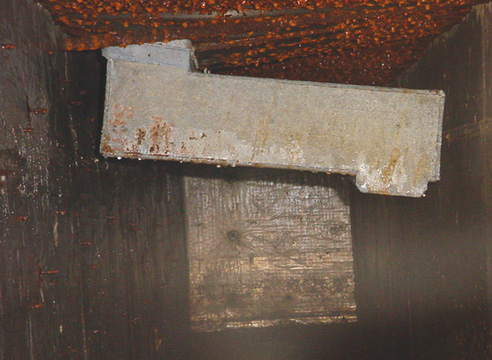 Figure 1
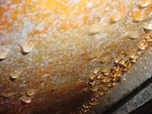 Figure 2
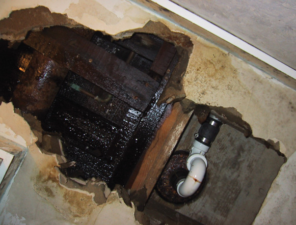 Figure 3
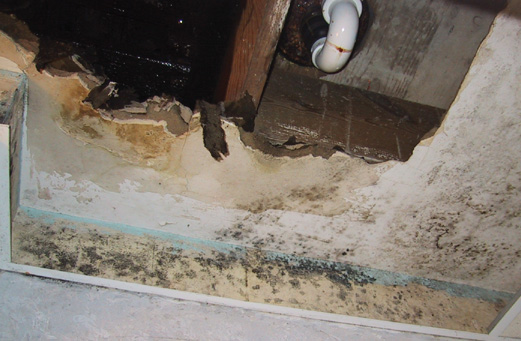 Figure 4
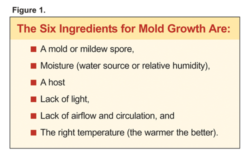 Figure 5
 Figure 6


