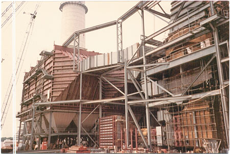
At power generating facilities there are fans that require both sound and thermal treatments, and others that only require one treatment or the other. These fans can present problems for sound and thermal control.
Fans produce two different types of noise-tonal and broadband. A tonal noise is generated when the blades pass by a stationary cutoff within the fan. A broadband noise is produced by the flue gas moving through the system. Both noise types are generated inside the fan. The sound travels out of the inlet box opening through the outlet flue of the fan and through the fan casing. All three paths must be considered in noise control. Inlet and outlet sound levels are most commonly controlled by adding absorptive or resonant-type silencers to the fan.
Acoustical insulation and lagging can be applied around the fan to limit the noise radiated from the casing. When noise reduction lagging and insulation is required, the effect of insulation thickness and optimal amount of jacket mass should be considered for the best economic value. Also, it’s always more cost effective to treat the noise at the source.
The following terms are most commonly used when considering fan noise and sound control.
- Noise
- Noise is simply unwanted sound. For this discussion, sound and noise will mean the same thing. Noise is measured with a sound level meter, which measures the sound pressure level.
- Decibel (dB)
- A decibel is the common unit of measure of sound. There are several standard weightings used for various reasons. In this case we shall only be concerned with "A-weighting."
- A – weighting
- A – weighting is the frequency sensitive corrections applied to linear sound level readings to approximate the way humans perceive sound.
- Free Field
- Free field refers to any wide-open area or space that has nothing around to reflect or interfere with sound in any direction.
- Flue
- Flue identifies a piece of equipment or component that has boiler exhaust gas passing through it (i.e. flue from the air heater to induced draft fan).
- Duct
- Duct identifies a piece of equipment or component that has air passing through it (i.e. duct from the forced draft fan to steam coil air heater).
- Fan
- A fan is a piece of equipment that consists of a bladed rotor or impeller, located in a housing, and designed to collect and redirect the air or gas by adding sufficient energy to the medium to initiate motion and overcome resistance to the flow.
- Forced Draft Fans (FD Fans)
- Forced draft fans are located before the air heater inlet. They move air temperatures ranging from ambient to 200 degrees Fahrenheit (F), depending on where the steam coil air heater is located (before or after the FD fan). Most often, the FD fan is located before the steam coil air pre-heater and will not require any thermal insulation for personnel protection, but may require acoustical sound and noise protection.
- Induced Draft Fans (ID Fans)
- Induced draft fans (ID fan) are located at or near the stack, and normally move gas temperatures ranging from 350 degrees F to 150 degrees F. Steam-generating boilers designed to operate with a balanced furnace draft or without a forced draft fan require an ID fan. An ID fan will draw the flue gas out of the boiler through the air heater and air pollution equipment and then exiting up through the stack. The operating temperatures of the ID fans will require thermal insulation for personnel protection and may also require acoustical sound and noise protection.
- Gas Re-circulating Fans (GR Fans)
- Gas re-circulating fans (GR fans) are used for controlling steam temperature, furnace heat absorption and slagging of heating surfaces. GR fans are located in a flue system that is re-circulating or sending gas back to the furnace for reheating. Gas from the boiler, economizer or air heater outlet is re-introduced to the furnace by the GR fans. The flue gas temperature that the fan is re-circulating back to the furnace is between 500 degrees and 700 degrees F, depending on where the flue gas is taken. In most instances, the flue gas is obtained from the economizer outlet flue. The operating temperatures of the GR fans will require thermal insulation for heat conservation, and may also require acoustical sound and noise protection.
- Primary Air fans (PA fans)
- Primary air fans (PA fans) are used for controlling airflow into a pulverizer (used to grind coal). The air amount and velocity will help in the combustion of fuel for the steam-generating boiler. The air drawn from the air heater is usually in a temperature range between 400 degrees and 700 degrees F, depending upon the size of the boiler. The operating temperatures of the PA fans will require thermal insulation for heat conservation and may also require acoustical sound and noise protection.
- Secondary Air Fans (SA Fans)
- Secondary air fans (SA fans) are used for controlling airflow into a windbox (a large vestibule that houses the burners). The air amount and the air velocity will aid in the fuel combustion for a steam-generating boiler. The air drawn from the air heater is usually in a temperature range between 400 degrees and 700 degrees F, depending upon the size of the boiler. The operating temperatures of the SA fans will require thermal insulation for heat conservation and may also require acoustical sound and noise protection.
Thermal and Acoustics
There are many ways to insulate and lag a fan. Most thermal insulation applications provide some type of acoustical benefit. However, the attachment method and the thermal insulation system location are critical for sound protection.
For example, if dealing with noise that’s radiating from the vibrating surface of the fan, installing a layer of rigid insulation material tightly against a fan housing would only create a larger vibrating surface and produce higher noise levels. Therefore, avoid a thermal and acoustical insulation system that uses a rigid attachment. The most logical method, in this case, would be to build a thermal/acoustical wall system around the fan. This system would be able to absorb some of the sound on the fan side, but not vibrate along with the fan. This can be done using a freestanding wall system or a system using isolators that would act as springs or shock absorbers. Either method requires space around the fan and can become expensive to install. The norm is to install a wall system of prefabricated panels secured to a frame that’s attached to the fan at a minimum number of well-chosen places.
To design an insulation/acoustic system, follow these steps:
- Inspect the fan and its surroundings before selecting treatment methods to reduce the fan noise. Other nearby noise sources will affect your design.
- Take into account the amount of room around the fan and its surrounding noise levels. This will determine the attachment method.
- Remember that regardless of how much you reduce the noise from a fan, the surrounding area can’t be quieter than the combined noise from the other sources.
Sound Levels
The Occupational Safety and Health Administration (OSHA) has set certain standards to protect workers exposed to noise levels. OSHA Standards number 1910.95 for noise exposure states that the employer shall administer a continuing effective hearing conservation program when employees are exposed to an average sound level of 85 decibels or more in an eight-hour day. In the steam and power generating industry, this usually means requiring earplugs and adding acoustical sound protection to their equipment (such as fans).
The chart that follows represents the A-weighted sound levels and the duration a person can be exposed to that level of sound per day. However this A-weighted chart is based on measurement by a dosimeter or a sound meter.
| Duration Per Day | Sound Level |
|---|---|
| 8 hours | 90 decibels |
| 6 hours | 92 decibels |
| 4 hours | 95 decibels |
| 3 hours | 97 decibels |
| 2 hours | 100 decibels |
| 1-1/2 hours | 102 decibels |
| 1 hour | 105 decibels |
| 1/2 hour | 110 decibels |
| 1/4 hour or less | 115 decibels |
OSHA amended or adjusted the preceding values for the human ear, known as a Time Weighted Average (TWA) and set 50 percent as the equivalent value. The formula OSHA used to set this new value was TWA=16.61 log (10) (D/100) + 90, where D represents the accumulated dose in percent exposure. This means that OSHA, to protect the employee, has set a TWA value of 85dB (not the A-weighted value of 90dB) as the maximum permissible sound level for an 8-hour exposure period.
Acoustical System Materials
Lagging is a common element in most acoustical surface treatments. The lagging material is usually aluminum or galvanized steel. Galvanized steel lagging is often better than aluminum lagging because steel has a heavier surface mass. The particulars of the noise problem may dictate what type of lagging will be used. For example, if the noise is a low frequency problem (a rumble type noise) then a lagging with more mass like galvanized steel is desirable. If the noise is mostly at high frequencies (a hissing noise) then a lighter material like aluminum lagging may be used. There are many other considerations, such as stiffness, ring frequency, transmission loss versus frequency, and other conditions that should be considered.
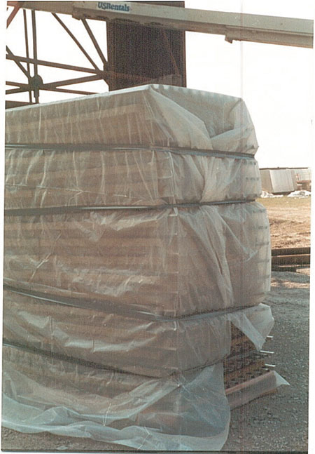
Insulation used as the absorptive filler in acoustical systems can vary, but it’s common to use basalt or mineral wool type insulation. Fiberglass is more popular at ambient temperatures and a better sound absorber. Ceramic fiber is used extensively in combustion turbine exhaust systems where temperatures often exceed 1,000 degrees F. It’s important to choose the right insulation material to fit the conditions of service.
Septum lining barriers are sometimes used between the absorptive layers of insulation in surface treatments to improve the sound transmission loss across a composite wall. Septum linings are usually made of a limp mass such as a mass loaded rubber or vinyl material. Perforated metal facings are frequently used to protect the insulation from erosion. The perforated facing will allow noise to pass through to be absorbed by the insulation.
A Typical Fan Problem
Here’s an example of a typical fan problem. A company orders two new forced draft centrifugal fans and two new motors from different vendors. Being safety conscious, the company specifies both the motors and the fans, when measured at a distance of 3 feet away, can’t have noise levels in excess of 85 dB. The fans and motors are tested at their respective factories and are confirmed to operate at 85 dB as specified.
Upon arrival at the site, the fans and motors are installed close together in an out-of-the-way spot of a corner formed by two painted, masonry block building walls. Immediately upon startup, it’s apparent that the fans and motors together are very noisy. A noise measurement confirms a level of 96 dB near the fans.
The next step is to look at the problem. Here are two fans and two motors each capable of producing a noise level of 85 dB in a free field. Remembering that decibels are logarithmic terms, we have to add all four logarithmic values together of all the equipment that’s located in the same free field. We find that four 85’s add up to 91 dB. Next, the review of the location of the fans and motors show they’re located between two building walls that form a corner. Sound reflecting back from walls forming a corner can amount to as much as 5 dB. This then accounts for the measurement of 96 dB.
The available means to mitigate the noise are:
- Acoustical Covering
- Acoustical coverings are necessary for any successful solution.
- Motor Silencers
- Motor silencers can be purchased from several companies who specialize in this form of noise control and can be custom designed. A motor silencer typically consists of an acoustically lined shroud around the motor casing, with an absorptive silencer directing cooling air to the motor fan. The biggest problem to look for when adding a motor silencer is the potential for overheating the motors.
- Absorptive Material on the Building Walls
- Absorptive material on the building walls can optionally help by reducing the amount of necessary treatment. Adding absorption materials on building walls can achieve fairly low cost results depending on the aesthetic requirements. This can be as simple as adding absorptive blankets consisting of fabric-covered absorptive insulation material placed on portions of the reflective surface.
- In-line Silencers
- In many cases, In-line silencers are a viable option if the fan ductwork is extensive and there’s no requirement for thermal insulation. Adding in-line-silencers in the ducts near the fans can replace extensive areas of surface treatment.
The cost of reducing the motor noise with motor silencers, compared to the cost of reducing casing/duct radiated noise by acoustical coverings, is estimated to be about the same per dB. Therefore, it would be logical to reduce both by the same amount. For this example, we shall opt not to use any absorptive treatment on the building walls. We must take into account the 5 dB of the untreated surrounding building walls. This means the sum of our four treated noise sources (two fans and two motors) must now be 80 dBA (85 dBA minus the surrounding build-up noise of 5 dB). To achieve the 80 dB, we have to add all four logarithmic values together. When we do that, we find that four 74’s add up to 80 dB.
Our next step is to take our original combined sound level value for the fans and motors of 91 dB and subtract the revised combined sound level value of 80 dB. This leaves 11 dB of noise that must be accounted. This 11 dB will require only nominal motor silencers and acoustical lagging treatment being added. In our example, the ductwork of the fans required no thermal insulation, were fairly extensive in length, and their noise contained only a noticeable amount of tonal noise. Therefore, it was decided to install a tuned-dissipative in-line silencer in the duct fairly near the fan. Finally, we extended the acoustical covering of the casing and ducts to the middle or end of the silencer (away from the fan).
Since there is ample room around the equipment, the acoustical covering can be achieved by either of following methods:
Example 1
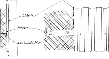
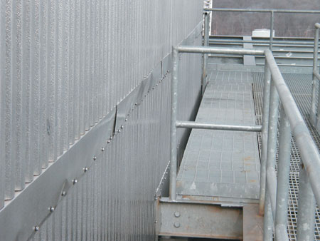
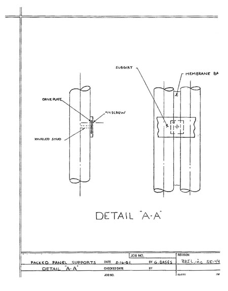
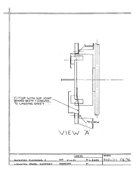
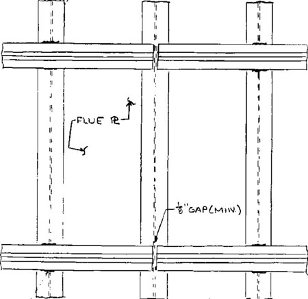
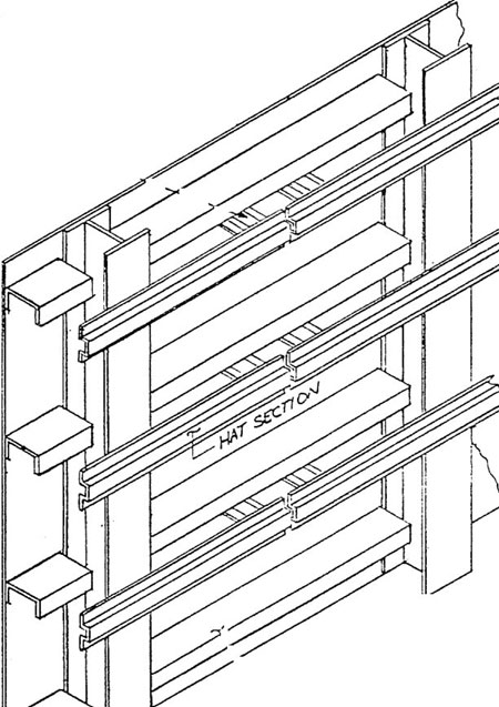
Against the fan housing – A support system could be installed to support the acoustical insulation and lagging system. This may be done by a built-out angle support and sub-girt system or by utilizing the existing fan stiffeners to achieve the appropriate air space and wind loading requirements. Then a *pre-insulated lagging panel system or a **conventionally built-up insulation and lagging system can be installed.
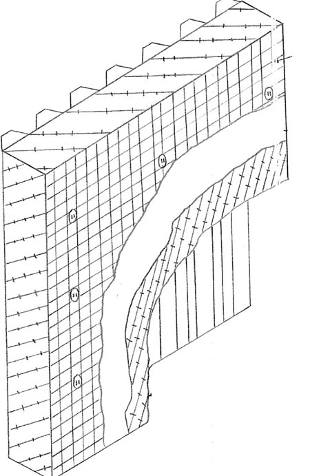
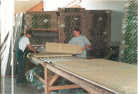
*A pre-insulated lagging panel system is a lagging and insulation system that consists of a shop-or-field fabricated lagging sheet lined on the backside with insulation. The lagging is laid face down on a table in the shop. The insulation pins are welded to the lagging sheet on approximately 12 inch centers. The insulation material is impaled over the pins in double layer application with a septum lining between each layer. Aluminum foil is placed over the insulation and will reflect some of the heat back in and is equivalent to about a 1/2 inch of insulation. A galvanized mesh (generally 2 inches x 2 5/8 inches, 16 gauge) is placed over the foil. The mesh keeps the insulation in place and will prevent the fibers from settling to the bottom or eroding away. A 2-1/2 inch square speed clip is placed on the pins, which are bent over to hold the panel together. This insulated lagging sheet or panel will then attach to the outside of the stiffeners directly or to a sub system made from angle iron.
**A conventionally built-up insulated and lagged system is a lagging and insulation system where each component (insulation and lagging) will be attached separately.
Example 2
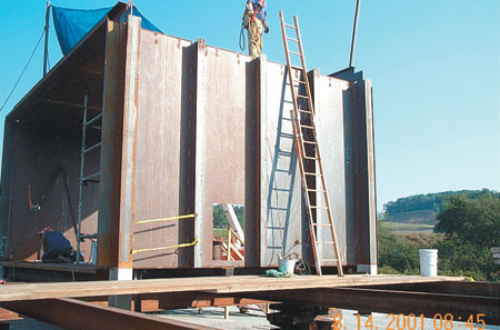
Sound enclosure – Acoustic sound panels would be fabricated in the shop or in the field at a location and then attached to a steel structure. This steel structure would be independent of the fans and the sound enclosure would completely enclose the fan.
Enclosures, duct silencers, motor silencers, and sound absorptive panels are only some of the tools needed to effectively control noise. No one product or method works for every situation. However, in most cases, any reduction of noise and creating sound control will benefit all work environments.