This article will explore what plant owners, Air Quality Control System (AQCS) equipment suppliers, and insulation contractors get when they purchase a pre-engineered and pre-fabricated insulation system.
Pre-fabricated panel insulation systems have been used extensively on above-ambient AQCS ducts and equipment at pulverized coal (PC) electric plants since the 1970s. Over a period of roughly 10 years, several hundred PC plants added or were retrofitted with equipment for separating the fly ash from the flue gas to bring the plants into compliance with the Environ-mental Protection Agency’s current Clean Air Act rules. Early AQCS equipment, consisting of either precipitators or bag houses, had to be well insulated for both personnel protection and process control. The insulation systems used for this equipment generally were pre-fabricated panels for the specific ductwork, hoppers, fans, and other sections of the AQCS. In some projects, the systems were pre-engineered; often, the panels were factory-assembled prior to delivery to the job site.
A quarter of a century later, most existing PC plants already have fly ash (i.e., particulate) collection systems. They are now additionally being retrofitted with selective catalytic converters and flu gas desulfurization scrubbers—the former for removing nitrogen oxide (NOx) gases and the latter for removing both sulfur oxide (SOx) gases and mercury compounds. NOx, in the presence of sunlight and warm air, will form smog particles; SOx, in the presence of water vapor, will form sulfur-containing acids. Both can lead to respiratory problems, and the latter contributes to acid rain that leads to water quality problems, fish kills, damage to stone structures, and corrosion of metal structures. Mercury compounds are toxic to all forms of life.
The dozens of proposed new coal-fired power plants, whether of PC or another design concept (such as fluidized bed combustors), must meet current Clean Air Act rules: They must be designed and constructed with appropriate AQCSs to remove pollutants from the flue gas prior to release into the atmosphere.
The bottom line is that there is a lot of work for the next few years in the United States for both the engineering firms who specify these modern AQCSs and the companies who design and fabricate the systems. Consequently, there is an increasing amount of work for mechanical insulation contractors who are experienced and skilled in installing pre-fabricated insulation panel systems at electric power plants. A typical project for the insulation contractor is to insulate 100,000 to 500,000 square feet of duct and equipment surface area with pre-fabricated insulation panel systems. These insulation contractors have found that the more pre-fabrication they can have done for them, the better they can control their costs and manage risk on the project. Furthermore, the more pre-engineering that can be done on the insulation panels, the better the thermal and structural performance, the better the fit, and the lower the operations and maintenance costs for the plants’ owners.
Terminology
It is useful to define some terms: pre-engineered, pre-fabricated, and pre-assembled insulation panel systems.
Pre-engineered insulation panel
system: A rigid panel insulation system for equipment operating at above-ambient temperatures, with thermal and structural calculations—and sometimes acoustical testing and calculations as well—designed to meet particular project criteria. This type of panel system design includes project-specific assembly drawings giving the construction, weight, dimensions, quantities, location, and attachment details for installation onto the industrial equipment to be insulated.
Pre-fabricated insulation panel
system: A rigid panel insulation system composed of precision-cut metal parts and insulation materials such that the system’s components can be installed by skilled craft laborers on the equipment to be insulated with minimal cutting and forming in the field. The metal parts and insulation may be delivered to the job site either unassembled or pre-assembled.
Pre-assembled insulation panel
system: A rigid panel insulation system composed of precision-cut metal parts and insulation materials and fully assembled into discrete insulation panels. These panels can be installed by craft laborers skilled on the equipment to be insulated with the metal lagging, panel structure, and insulation boards in pre-assembled, discrete units.
Responsibility for Performance of Pre-engineered Insulation Panel Systems
There is always an engineering firm or an engineering, procurement, and construction (EPC) contractor responsible for the overall AQCS design. However, there are also an AQCS equipment designer/supplier, a pre-fabricated panel insulation system supplier, and an insulation contractor involved, so the question of who is responsible for the insulation panel system design can be complex. The engineering firm or EPC contractor probably has a specification for pre-fabricated insulation panel systems. The AQCS equipment designer/ supplier also probably has his own specifications—his panel insulation system design may be specifically tailored to his own equipment. If there is a pre-fabricated insulation panel system supplier, he should have his own in-house engineering and design capabilities. Finally, the insulation contractor typically is responsible for correctly purchasing and installing the system to the both the intent and requirements of the specification. His purchase order is likely to include a specification for the pre-fabricated insulation panel system with performance criteria; therefore, the insulation contractor likewise ends up with design responsibility. Without some clarification (perhaps contractual clarification), there is no simple, “one size fits all” answer to the question of who has design responsibility for the pre-fabricated insulation panels.
Materials Used
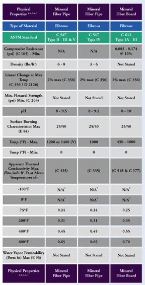
The insulation materials typically used are almost always mineral fiber boards or blankets, in compliance with either ASTM C612 or C553, that meet the high temperature requirements. Mineral fiber boards or blankets are selected for a combination of factors. Boards or blankets should meet the following requirements:
- Are compressible and resilient, and so can be easily handled without damage
- Can be cut easily and penetrated with attachment pins
- Are lightweight (typically having a bulk density in the 2.5 to 10.0 pcf range)
- Are effective insulators, with a thermal conductivity less than 0.24 Btu-in/hr-ft2-°F at a mean temperature of 75° F
- Do not contribute corrosive chemicals when wet
- Are partially water repellent prior to first high-temperature exposure (valuable during construction)
- Easily drain and dry out when they get wet after high-temperature service
- Are not flammable
- Provide specified acoustical control in designated locations
High thermal efficiency materials, such as microporous insulation, are sometimes used where space limitations preclude full thickness of the mineral fiber insulation.
Required Thermal Performance
Usually, one of the insulation requirements includes providing personnel protection, which means keeping outer surface temperatures below 140°F on a windless, hot day, including consideration of the lagging emissivity (but without consideration of the effects of sunlight). Second, the insulation is intended to keep the flue gas from cooling below some threshold value as it travels through the duct. The longer the duct or the slower the flue gas flow rate, the lower the required thermal conductance of the insulated panel (or, alternatively, the greater the required insulation thickness). The maximum allowable temperature drop of the flue gas is then a function of several factors: the flue gas’ properties, its initial temperature as it enters the ducts and equipment, design (winter) ambient conditions, the ducts’ and equipment dimensions, and the ducts’ and equipment walls’ effective thermal conductance.
Heat flow analyses would be simple if the thermal design could assume one-dimensional heat transfer such that all heat flow is only through the insulation itself. However, some allowance must be made for additional heat loss through subgirts that cut through the insulation, from the hot side to the cold side, creating “thermal bridges.” This additional heat loss can be estimated either by hand or by computer calculations, the latter using a finite element or similar model. Regardless, the additional heat loss can be considerable with consideration for thermal bridging through the subgirt: it might be 25 to 50 percent greater than it would be for simple, one-dimensional heat flow through the insulation with no thermal bridging. The exact percentage depends on the panel system design and thermal design conditions.
Required Structural Performance
Specifics can vary from one location to another. In general, the panel system must withstand its own weight vertically, as well as a design vertical and horizontal seismic loading, a certain horizontal wind loading (usually based on hurricane or tornado conditions), snow loads, and foot traffic. Additionally, the system must accommodate ducts and equipment thermal movement in all directions. Hence, calculations made to establish the structural adequacy of the proposed design should be provided by the pre-fabricated insulation panel system supplier. Additionally, on horizontal ducts and equipment, the top surfaces must withstand foot traffic loading and so usually use thicker aluminum lagging.
In addition to the above thermal and structural design requirements, the insulation system must be designed to allow for water run collection and run-off.
The Importance of Engineering
If a panel insulation system is indoors, protected from wind and other environmental impacts, the engineering requirements are much less demanding. In such cases, it may be practical to have the aluminum lagging supported by pins holding the system to the flue gas ducts and equipment sidewalls. One such system is shown in Figure 9.
Note that in the system shown in Figure 9, the weight of the entire system is supported by capacitor discharge (CD) weld pins shot to the duct’s surface (refer to the detailed description given in the caption). While this may be structurally adequate for indoor applications, it may be insufficient for outdoor applications where the panel system would be expected to withstand high wind loadings (up to 110 mph). Figure 9 also shows the “Riley-Stoker Hat” subgirt and strap support, and the upper right corner illustrates the representative duct plate with the CD weld pin welded to the plate. The mineral fiber insulation is placed over the pins and against the duct plate, and a “speed washer” is placed on the CD weld pins and pushed tightly against the insulation. A pre-punched strap is placed over the pins and secured with suitable clip fasteners, to which the “Riley-Stoker Hat” subgirt is welded. The box rib lagging is then applied over the wall and is held in place with self-drilling screws to the “Riley-Stoker Hat” subgirt.
Figure 10 shows a mock-up for a modified H-bar system, which can easily be designed to withstand a high wind loading. In this design, the entire insulation panel system is installed outside the vertical duct stiffeners (as opposed to between those stiffeners and directly to the duct’s surface), providing a uniform exterior surface. The horizontal J-bar (upper) and H-bar (lower) are either welded or mechanically attached to channel standoffs that, in turn, can be either welded or mechanically attached to the vertical duct stiffeners. The vertical mineral fiber board is slightly oversized and compressed (to allow for thermal expansion) between two horizontal, parallel H-bars, leaving a vertical (i.e., still) air space between the boards and the duct surface. Where thermal movement considerations must be accounted for in the design, an expansion clip is used to secure both the J-bar and the H-bar. This allows for thermal movement of the duct plate and stiffeners relative to the lagging. Also of significance are the weld pins used in the H-bar as a top retention device for the insulation. This allows for a better compression fit of the insulation, which does not have to be deflected or deformed in any way to be worked between two flanges. The absence of the lower flange also allows for visual verification of the insulation fit at the top edge, where it is most likely to be shy of the subgirt, thus producing a cold spot for the duct and a thermal “hot spot” for the lagging.
To prevent high air movement and therefore higher-than-design heat transfer in that space, insulated convection barriers (continuous shelves composed of expanded metal with mineral fiber boards on top) are used. The box-ribbed aluminum lagging is screwed to the H-bars; however, woven fiberglass tape, adhered to the flange of the H-bar, acts as a thermal gasket to prevent high heat conduction through the H-bars to the lagging. This system has been designed by the pre-fabricated insulation panel system supplier for rapid installation of the mineral fiber boards (between the parallel H-bar and J-bar), capability to withstand high wind loadings, and ability to provide good thermal performance through the use of convection stops and thermal barrier fiberglass tape. These engineering features are to be expected with a well-designed panel system.
Conclusions
Pre-fabricated insulation panel systems can be made in a variety of designs. The facility owner and the insulation contractor both benefit if they specify and purchase a pre-engineered system that is custom designed for the particular project and supplied with thermal calculations, structural calculations, and assembly drawings showing where all the parts and pieces are to be installed. Furthermore, both obviously benefit from quality fabrication where the drawings match the delivered parts. The benefits are both short- and long-term. In the short term, the schedule and cost of the construction of the new AQCS component being added to the plant are well managed. Long term, the system provides the expected thermal performance, endures high wind conditions and external loads such as foot traffic, and allows accessibility for plant maintenance personnel. There are benefits if the project starts with
a comprehensive, detailed specification that requires the pre-fabricated
insulation panel system also to be fully engineered.
 Figure 1
Insulators install a pre-fabricated aluminum box rib panel over a modified H-bar system, with the mineral fiber boards already installed on the flue gas duct sidewall. Note that while this system was pre-engineered and pre-fabricated, it was not pre-assembled; assembly is being done in the field by these insulators.
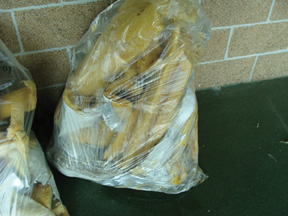
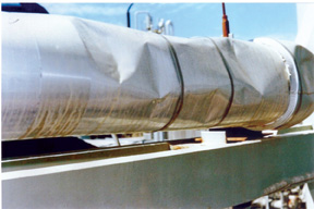
 Figure 2
These two photos show pre-assembled panels, with the mineral fiber boards already impaled onto the aluminum box-ribbed panels, installed with screws to the pre-installed sheet metal flashing. Since they are cut to size, came with drawings showing where each should be installed, and have thermal and structural engineering calculations that support the design, this system is also pre-engineered. The panels were pre-fabricated at a remote shop and shipped to the power plant, several hundred miles away.
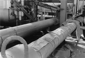
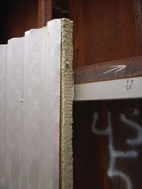 Figure 3
These two photos show pre-assembled panels, with the mineral fiber boards already impaled onto the aluminum box-ribbed panels, installed with screws to the pre-installed sheet metal flashing. Since they are cut to size, came with drawings showing where each should be installed, and have thermal and structural engineering calculations that support the design, this system is also pre-engineered. The panels were pre-fabricated at a remote shop and shipped to the power plant, several hundred miles away.
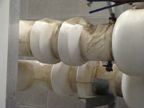
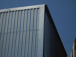 Figure 4
This pre-engineered, pre-fabricated, and pre-assembled insulation panel system was installed relatively quickly by the insulation contractor because all the panels had been cut to size and designed for a specific location, shown on the panel fabricator’s assembly drawings. These drawings will be extremely valuable in the future for the power plant owner, as they provide a record of what is where, should any panels need to be removed for maintenance or inspection.
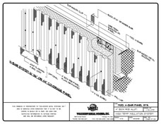 Figure 5
Engineering drawing showing the assembly of a pre-fabricated, modified H-bar/panel combination system with a sound barrier material between the aluminum box-ribbed panel and the mineral fiber insulation board. Provided by a firm that pre-engineers and pre-fabricates these panels, this drawing shows details not otherwise available, such as the size and type of attachment screws.
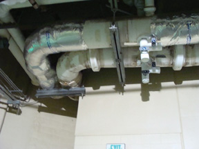
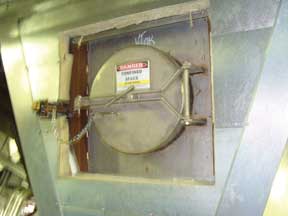 Figure 6
A pre-fabricated door will be installed onto this hopper to provide access to the access port for maintenance. Such access is critical for the facility owner, who must operate and maintain the facility.
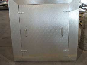 Figure 7
A pre-fabricated door will be installed onto this hopper to provide access to the access port for maintenance. Such access is critical for the facility owner, who must operate and maintain the facility.
 Figure 8
Modified H-bar insulation system being installed on the top side of AQCS ducts at a PC electric power plant being retrofitted. This pre-fabricated system must be designed for thermal performance, wind loading, seismic accelerations, snow loads, and foot traffic; provide proper slope to allow water run-off; and allow for quick installation by the insulation contractor.
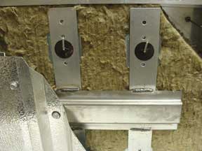 Figure 9
: In this photo of a mock-up, this system is typically referred to as a “conventional, pinned-to-the-skin” system using a “Riley-Stoker Hat” subgirt and strap support.
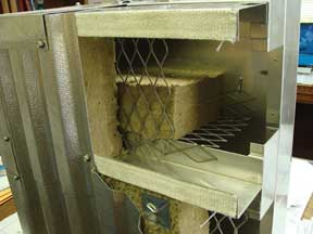 Figure 10
The essential details of a modified H-bar panel system. The advantages of this design and others that support the lagging off the duct’s stiffeners include that they can withstand high wind loading, which the “Riley-Stoker Hat” subgirt and strap support design, shown in Figure 7, cannot.
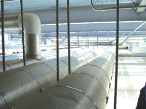
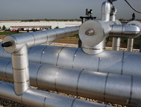
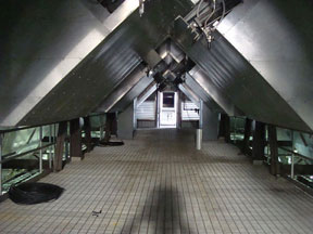 Figure 11
The upper sections of a row of hoppers on a bag house that filters out fly ash from the flue gas. Note the excellent fit of the pre-fabricated insulation panels, resulting from the efforts of both the panel system supplier and the insulation contractor. With its indoor location, protected from the elements, this system does not need to be designed for high wind loads, snow loads, or other outdoor environmental factors.