Category Archives: Environmental Control

Sustainability—Key Terms & Concepts

The sustainability conversation has brought up a whole new vocabulary. Here are definitions of a few of the terms to help clarify the discussion.

Greenhouse gas (GHG) emissions are considered to fall in one of three categories (“scopes”):

  • Scope 1 emissions are those that come directly from sources owned or controlled by an organization. Examples include emissions associated with direct use of vehicles, furnaces, boilers, etc.
  • Scope 2 emissions are indirect and come from the energy an organization buys (heat, cooling, electricity, steam)
  • Scope 3 emissions are those from activities outside an organization’s control or ownership but that are impacted indirectly by the organization’s value chain. Examples includes emissions generated by sources like the organization’s employees, suppliers, and all upstream and downstream “value chain emissions.”

The scopes are important because they help businesses identify where most of their emissions are generated, allowing them to focus improvement efforts to have the greatest impact. More information is available on the Environmental Protection Agency’s website at https://www.epa.gov/climateleadership/ghg-inventory-development-process-and-guidance

Carbon Capture and Storage/Sequestration (CCS) is the process of capturing CO2 before it reaches the atmosphere, then transporting and storing it.

Carbon Capture Utilization/Usage and Storage (CCUS) is the process of capturing CO2 emissions from large sources like industrial plants and power stations, or from the atmosphere, and transporting it to either be reused or stored in deep subsurface formations (such as depleted gas and oil reservoirs) where it can be stored permanently

Embodied Carbon is the total amount of carbon arising from a building’s construction, to include extraction and refinement of raw materials, and the manufacturing, transport, installation, maintenance, and disposal of building materials.

Environmental Product Declaration (EPD®) is a report that documents a product’s measured environmental impact. EPDs are developed in accordance with ISO standards and guidelines, are valid for 5 years, and provide an independent, third-party assessment of a product’s impact on the environment. In construction, they are used by consumers, designers, architects, developers, engineers, and others to create more sustainable buildings. (See also Life Cycle Assessment)

Life Cycle Assessment (LCA) is an analysis of the environmental impact of a product throughout its entire life cycle—i.e., from extraction of raw material through manufacturing, distribution, transport, use, maintenance, and eventual disposal or recycling.

The Saint Gobain building study was undertaken for the purpose of being able to get quantified metrics on how exactly building and design choices affect personnel and thus, business operations. The subjects were studied for 3 years in the first building, and then before and after they moved into the new building. The unique circumstances of this longitudinal case study—being able to study the same group of people in 2 different buildings—removed some of the variables and made it easier to draw conclusions from the available evidence. One of the objectives was to prove that you can build a high-performance building on a budget, and the study helped identify what design choices would give the best results.

One investment that paid off big in this project was insulation. Lucas Hamilton, Manager, Building Science Applications at CertainTeed, affirmed, “we went crazy on acoustics” because of how vital they were to the project’s overall success. Since the building had an open-plan office, acoustics were critical to allow people to be able to speak without feeling that they’re disrupting others. To support the open plan, private spaces were built throughout the building at a ratio of one for every 8 people. These spaces promise the chance for complete quiet or private conversation, which wouldn’t be possible without insulation. These quiet rooms have walls that are stuffed with sound attenuation batts, are continuous and air sealed deck to deck, and the rooms are conditioned with supply and return air ducts. In such rooms, it’s often the ductwork that compromises privacy. For this reason, the ducts have been lined with duct insulation, making them essentially silent.

When you’re looking for excellent acoustical performance and thermal efficiency, insulation is a single material doing multiple jobs. Hamilton noted, “Every bit of ductwork in the building is insulated. It’s so hard to commission a building without proper use of insulation—you need it if you want air coming out at the same temperature throughout the system.” Failing to insulate the ductwork makes it extremely difficult to keep the air at a consistent temperature. As the duct runs get longer this is even more true. Hamilton said, “You can’t get the results you need without a well installed insulation package—it’s really important for controlling the temperature and the energy loss. Without insulation, you’re losing energy every foot you get away from the source.” Temperature consistency not only saves energy, it’s also critical to thermal comfort, which can have a significant effect on employee health and productivity.

Hamilton explained that if you’re looking for above-board results, you have to shift the focus away from up-front costs and look at costs over the life of the building. Oftentimes, choosing an insulation with a better R value will pay for itself very quickly at today’s energy costs. The focus on choosing materials and design that would garner long-term benefits on this project resulted in the building gaining platinum LEED status in both Core and Shell, and Commercial Interiors programs.

In addition to helping meet energy goals, insulation also aids in maintaining Platinum LEED status due to the role it plays in moisture management, which is important for air quality. Saint Gobain used a vapor retarder in the exterior walls of the building that played an important role in managing moisture. This vapor retarder is a material that, on the microscopic level, closes and opens based on the amount of moisture present in the air. This allows the wall to dry when necessary. Hamilton noted, “Moisture is coming and it will eventually find a way in, so you need the materials that can respond and work to keep the
building dry, healthy, and performing at a high level.”

Saint-Gobain’s headquarters and its office configuration would simply not be effective without the use of insulation. In this instance, the insulation will not only save energy and keep costs low throughout the life of the building, but also help with employee comfort and productivity. Hamilton said, “You need the full variety of insulation options to get all of this right. Everyone thinks you just shove insulation in a wall and forget about it, but you have to get it right the first time because it’s hard to fix once the walls are built. There’s so much thought and work that goes into this material that is so hugely impactful down the road. Winston Churchill said we shape our building and then they shape us—our time to get it right is when we put it [the insulation] in because it’s going to affect our lives from then on. It’s such an incredibly important influence on whether people are happy.”


Copyright Statement

This article was published in the October 2018 issue of Insulation Outlook magazine. Copyright © 2018 National Insulation Association. All rights reserved. The contents of this website and Insulation Outlook magazine may not be reproduced in any means, in whole or in part, without the prior written permission of the publisher and NIA. Any unauthorized duplication is strictly prohibited and would violate NIA’s copyright and may violate other copyright agreements that NIA has with authors and partners. Contact publisher@insulation.org to reprint or reproduce this content.

This summer has seen a series of all-time heat records being set worldwide. In July, a global heat wave stretched over most of the northern hemisphere, with locations all over the globe recording their highest-ever temperatures. These dangerous heat waves are likely to continue and worsen, making energy efficiency and lowering environmental impact vitally important.

Mechanical insulation is an unsung hero when it comes to being green. Lowering the impact of fossil fuels is a critically important objective, and that’s precisely what a properly installed and maintained insulation system will do. The following quotes are from Christopher P. Crall. His “Insulation: Greener than Trees!” article, published in a prior issue of Insulation Outlook, is recommended reading and shines a light on exactly how green insulation can be.

Energy and CO2 Savings

As an example, consider a chemical facility that uses steam at 350°F in a manufacturing process that operates year-round. The steam is produced in an oil-fired boiler operating at an average efficiency of 80%. Cost of purchased fuel oil is $4 per gallon. The 4-inch steam header is outdoors and insulated with 2 inches of fiber glass pipe insulation. These calculations, shown in Figure 1, were made using the 3E Plus® computer program developed by the North American Insulation Manufacturers Association (NAIMA).

The use of insulation has reduced the heat loss from the bare pipe, on average, by 95%. The associated fuel cost has likewise decreased by 95% for a fuel-cost savings of $417 per foot per year. This 95% reduction in fuel usage translates to a 95% reduction in CO2 emissions, a savings of 2,309 pounds of CO2 per year.

As expected, the annual savings of $417 per foot per year is impressive and would undoubtedly yield a payback period measured in months. The reduction in CO2 emissions (2,309 pounds per foot per year) sounds impressive as well, but what does it really mean? How does that compare to other carbon-reducing technologies?

Insulation Is Greener than Trees!

Trees are an important part of the carbon cycle. Trees (and all green plants) use photosynthesis to remove and store carbon from the atmosphere (while at the same time releasing oxygen). In fact, trees are considered to be so beneficial that we can purchase carbon offsets associated with reforestation projects. One online site offered, for about $12, the opportunity to purchase enough carbon offsets to cover the carbon emissions from an automobile trip of about 2,300 miles (roughly the distance from Detroit to Los Angeles). The funds are invested in reforestation projects in Africa and Asia.

How much CO2 is absorbed by a tree? It varies with the type of tree, its location, and its stage in the life cycle. One source estimates that a single mature tree can absorb 48 pounds of CO2 per year. Another source estimates that, over an estimated 100-year lifetime, a cottonwood tree can absorb roughly 28 pounds of CO2 per year. A third source estimates that each tree will absorb 1 metric ton of carbon over its lifetime (equivalent to roughly 8,100 pounds of CO2 over its lifetime). I’m using a rough estimate of 50 pounds of CO2 per year. Figure 2 shows the simple comparison.

Wow. One would need to plant roughly 46 trees to achieve the same CO2 reductions achievable by insulating 1 foot of 350°F pipe.

But most pipes aren’t at 350°F. Some operate at higher temperatures, and many at lower temperatures. For illustration, consider a hot water heating system in a commercial building. Assume an operating temperature of 180°F and a 2-inch pipe with 2 inches of elastomeric insulation. For this application, assume a “clean,” natural-gas fired system operating at 75% efficiency. Use a fuel cost of $10 per million cubic feet (Mcf) for natural gas. Again using the 3E Plus program, the calculations shown in Figure 3 can be estimated.

In this case, the heat loss is reduced by 91% and the fuel cost savings are only $9 per foot per year. The CO2 emissions are also reduced by 91%, which translates to only 109 pounds per foot per year. This simple comparison is shown in Figure 4.

So one would only need to plant 2 trees to achieve roughly the same amount of CO2 reduction achievable by insulating 1 foot of these hot water pipes.

What about cold piping? Let’s take a look at a 4-inch chilled water pipe insulated with 1 inch of cellular glass insulation (see Figure 5). Assume that cooling is provided by electric chillers with a coefficient of performance of 3.0, and assume electricity is purchased at $0.10 per kilowatt-hour (kWh). Also, assume that the system is for a high-usage application that operates 95% of the time. 3E Plus yields the information in Figure 5.

For this case, the dollar savings are around $6 per foot per year, and the CO2 reductions are roughly 88 pounds per foot per year. The simple comparison is shown in Figure 6.

Again, one would need to plant 2 trees to achieve roughly the same annual reductions achieved by 1 foot of pipe insulation.

Clearly, insulation is a significantly more effective means of reducing greenhouse gas concentrations than planting trees. This conclusion supports the notion that it is easier to avoid carbon emissions than it is to remove carbon from the atmosphere.

So far, this discussion has not really considered the longer-term considerations of forests and the carbon cycle. Most researchers consider mature forests to be carbon neutral, in that they contain some vegetation that is young and still growing (i.e., absorbing CO2 from the atmosphere and storing carbon), but this is balanced by vegetation that has died and is decaying (i.e., giving up CO2 to the atmosphere or the soil). While established forests serve as a significant storehouse for carbon, any carbon stored in trees is eventually returned to the environment.

This discussion should not be interpreted as an argument for not planting trees. Trees provide many useful benefits. They provide shade in the summer, shelter for wildlife, and important building materials, and they are much more pleasing to look at than a piece of insulation. As a method for controlling greenhouse gases, however, insulation is greener than trees.

What about other carbon-reduction technologies? How does insulation stack up to some of the other methods being discussed?

What about more fuel-efficient cars? Combustion of gasoline releases about 20 pounds of CO2 per gallon of gasoline. Assuming 12,000 miles of driving per year, increasing the average fuel efficiency of a car by 1 mile per gallon (a 5% increase over the current national average of 20 miles per gallon) would save 29 gallons of gasoline per year and reduce CO2 emissions by roughly 570 pounds per year.

Clearly, insulation has a great deal to offer to energy-efficiency efforts. Although it may not be the newest or most exciting technology, there’s no arguing with the results it produces. Properly installed insulation can make the difference on whether a building meets its energy goals or not—making the use of insulation absolutely vital to an energy-efficient future.


Copyright Statement

This article was published in the August 2018 issue of Insulation Outlook magazine. Copyright © 2018 National Insulation Association. All rights reserved. The contents of this website and Insulation Outlook magazine may not be reproduced in any means, in whole or in part, without the prior written permission of the publisher and NIA. Any unauthorized duplication is strictly prohibited and would violate NIA’s copyright and may violate other copyright agreements that NIA has with authors and partners. Contact publisher@insulation.org to reprint or reproduce this content.

Author’s Note: “While Hurricane Harvey was devastating to some regions of Texas, to the best of my knowledge, the buildings mentioned in this article were not flooded by Hurricane Harvey. Even if the stadium and convention center had flooded, I engineered an insulation system that does not absorb water, so the system should not be damaged by water.”

Chilled-water (CHW) pipe systems must be carefully insulated to perform properly—this is even more true in hot and humid environments. The challenges inherent in such an environment caused many unusual issues for a multiuse professional football stadium and convention center located in south Texas near the Gulf of Mexico. This case study will help readers:

  1. Understand the causes and effects of CHW pipe insulation systems operating beyond design conditions;
  2. Comprehend the long-term effects of “idle building syndrome” on the CHW pipe insulation installations;
  3. Clarify the physical effects that would identify the rationale for remediating the failed CHW pipe insulation systems; and
  4. Ascertain the type of pipe insulation systems that can be installed on a 38°F (3°C) functioning CHW pipe and require no external vapor retarder (VR) jacket.

The football stadium in question is a 1.9 million sq. ft. (176.5 thousand m2) air-conditioned structure with a seating capacity of ≥72,000 people and a retractable roof. Water-cooled chillers with up to 18,000 refrigerated tons (216 million BTU/hr.) capacity supplied the 24” NPS, 38°F (3°C) CHW supply piping underground to the stadium. The original specified/designed space conditions were 72°F to 75°F (22°C to 24°C) conditioned air at approximately 50% relative humidity (RH).

The adjacent rectangular-shaped convention center is 3/10-mile (0.5 km) long and has 1.4 million sq. ft. (130 thousand m2) air-conditioned floor space. The same 18,000 refrigerated tons (216 million BTU/hr.) capacity water-cooled chillers supplied the 24” NPS, 38°F (3°C) CHW supply piping underground to the convention center, with distribution piping across the 40 ft. to 80 ft. (12 m. to 24 m.) high exhibit hall ceilings to the mechanical rooms with air-handling units (AHUs).

Inside the stadium and convention center, the insulated CHW piping suffered from occasional exposures to the south Gulf Coast of Texas’s high humidity and ≥90°F (32°C) ambient conditions. In addition, all the 38°F (3°C) supply and 54°F (5°C) return piping operated constantly in all areas where it was located, as all areas were designed as conditioned air spaces. In other words, the chilled water supply and the chilled water return distribution piping are flowing 365 days a year.

Although the stadium and convention center operated with 2 different types of CHW pipe insulation materials and accessories, both installation systems had several deficiencies and failed to perform to expectations. The following listed instances include installations practices, choice of materials and accessories, and specification requirements that led to some of the installed insulation system performance failures.

  • The CHW pipe insulation was installed with insufficient thickness to prevent condensation from forming on the outer jacket surfaces. In addition, the same thickness was installed on the CHW pipe finished with aluminum jacket, which is an issue since the lower emittance of unpainted aluminum jacketing usually requires higher thickness requirements.
  • The white paper–covered VR All Service Jacket’s (ASJ’s) longitudinal and circumferential joints were compromised during the formation of condensate water with poor lap closures and some staples. Consequently, some mold and mildew formed on a portion of the white paper ASJ jacket both with and without a PVC jacket.
  • The PVC-covered insulation fitting wrap contained no vapor retarders or jacket and the fitting cover closure was sometimes held together with thumbtacks.
  • Pipe insulation mitered fittings were covered with an open weave fabric and coated with a non-vapor-retarder mastic.
  • All the original pipe insulations installed were permeable, allowing the insulation (with poorly performing VR seal) to become moisture laden from condensation, starting the corrosion under the insulation (CUI) on the CHW pipe, pipe fittings, flanges, flange bolts, etc.
  • See Figure 1A: CUI on the inside on the metal surface under the 45° elbow insulated fitting.

  • See Figure 1B: CUI on the flanged coupling with partially corroded bolts.

  • See Figure 2: The stadium’s CHW pipe insulation starting to develop mildew fungi on the outer jacket, unlike the hot water pipe insulation on the left.
  • See Figure 3: The effects of high humidity exposures shown here with infrared thermal imaging. The stadium’s wet CHW insulated piping is shown on the right and the same hot water insulated piping is shown on the left.

New CHW Pipe Insulation Engineering and Design Requirements

The multipurpose stadium and convention center are constantly being prepared for and hosting various events year-round, requiring the zoned air conditioning to operate 24 hours a day, 365 days a year. Therefore, the remediation process on all the CHW pipe insulation systems had to be conducted while the CHW supply and return piping were operating at 38°F (3°C) and 54°F (12°C), respectively. Unfortunately, isolating the CHW distribution piping for insulating at ambient temperatures is not possible.

All the new pipe and equipment insulation CHW systems are designed to sustain some condensation water forming on the outer pipe insulation surfaces due to the high humidity surrounding air conditions. This makes it important to use a nonpermeable insulation, such as cellular glass with a 0 permeance charcoal-colored VR butyl joint sealant; an insulation material with these specifications can withstand the formation of condensation without negatively effecting thermal performance.

In order to minimize the likelihood of condensation formation, the cellular glass insulation manufacturer provided the thickness requirements—as specified by the owner’s engineering design team—to accommodate 90°F (32°C) ambient air temperature and 90% RH, with no (0) wind, and with a 0.9 emittance PVC or CPVC jacket, or with no VR jacket. Originally no aluminum jacket was installed, but this was revised to PVC jacket inside the buildings and CPVC jacket and fittings covers for outdoor insulated CHW piping. In addition, the cellular glass insulation manufacturer warrants that, for a period of 20 years from the date of completion of construction (July 2016) the cellular glass installed on chilled water piping in the building identified herein will not absorb moisture, and will retain its original insulating efficiency, compressive strength, dimensional stability, and will remain noncombustible.

Installing the New Insulation System

Considering that the pre-2003 CHW piping installations used lesser pipe insulation thicknesses, the owner’s engineering group provided engineering drawing work-around solutions to accommodate the newly designed increases in pipe insulation thicknesses. The primary reason for increased thickness was due to changes in increased design requirements (e.g., designed conditions increased to 90°F and 90% relative humidity and a functioning VR system). Thickness was not the issue. Although the design conditions are very complex, the installation of a vapor sealed cellular glass pipe insulation system provided the only solution to the remediation process.

After removal of the original insulations and accessories, the 38°F (3°C) supply and 54°F (12°C), return pipe was cleaned, wire brushed, and hand dried while all the cellular glass longitudinal and circumferential joints, and vapor dams within the annular space, were coated with the charcoal-colored VR butyl sealant and quickly installed on the CHW pipe and pipe fittings. It must be noted that all saw cuts made on jobsite are made by movable flat table band saw (no hand saws allowed) to provide perfectly fitted joint cut surfaces. After the new pipe insulation sections were permanently installed, the cellular glass pipe insulation was banded together with stainless steel strapping.

Since the cellular glass insulation will not absorb water vapor/moisture and has a 0.0 perm rating, only the pipe section joints are sealed and no additional vapor retarder jacketing system is necessary for this CHW insulated piping system. White PVC and CPVC jackets are used primarily for another form of aesthetics or protection from physical mistreatment.

Figures 4–8 show the aesthetic difference between insulated CHW cellular glass pipe insulations with and without jacketing. These photos are the finished applications:

  • Figure 4: 18” NPS stainless steel (SS) strapped sealed cellular glass pipe insulation with no jacketing located in the exhibit hall high ceiling.
  • Figure 5: Totally vapor-sealed joints of cellular glass 90° elbow with no external jacket.

  • Figure 6: 18” NPS SS strapped 3-foot sections of cellular glass pipe insulation installed in ceilings.
  • Figure 7: 12” NPS SS strapped cellular glass CHW supply and CHW return insulated pipes and elbows with no outer jackets.
  • Figure 8: 8” NPS SS strapped cellular glass CHW supply and CHW return insulated pipes and groove and clamp couplings covered with white PVC jacketing located in the stadium’s upper concourse ceilings.


Conclusions

There were several lessons learned on this project, prior to and during the remediation. It is critical for design engineers to consider and design the system for real-world conditions. Giving some thought to those conditions, and their impact on the long-term performance of the insulation system, pays dividends immediately. Consideration of issues such as “idle building syndrome” also pay dividends related to system performance. Choosing the most appropriate system based on real world conditions is important to achieving desired performance, as is making sure that any “value-engineering” processes actually add value. Finally, if remediation is necessary, choose an insulation system that is going to perform in the field considering all long-term local and surrounding conditions.


Copyright Statement

This article was published in the November 2017 issue of Insulation Outlook magazine. Copyright © 2017 National Insulation Association. All rights reserved. The contents of this website and Insulation Outlook magazine may not be reproduced in any means, in whole or in part, without the prior written permission of the publisher and NIA. Any unauthorized duplication is strictly prohibited and would violate NIA’s copyright and may violate other copyright agreements that NIA has with authors and partners. Contact publisher@insulation.org to reprint or reproduce this content.


The U.S. Green Building
Council (USGBC) unveiled the latest version of its Leadership in
Energy and
Environmental Design (LEED) program—LEED v4—at the
Greenbuild International
Conference and Expo in Philadelphia last November. The latest
version, classified
as a “quantum leap for LEED” by the USGBC, builds on the foundations
of the
previous version, LEED 2009, while incorporating new types of
buildings,
product selection criteria, impact categories, and credit-earning
calculations.

Consistent
with previous versions of LEED, LEED v4 includes prerequisites that
must be
satisfied to earn credit, as well as optional credit requirements.
However,
there are some notable differences in approach as well as the
addition of new
sustainability criteria. This article describes how and where the
selection and
use of insulation applies to LEED credits, with a specific focus on
the
Materials and Resources section, and changes to Indoor Environmental
Quality
criteria. Manufacturers of insulation as well as architects,
designers,
contractors, specifiers, and other users will continue to leverage
the benefits
of steps taken to earn LEED credits under the previous standard,
while also
accessing new credit opportunities with the strategic selection of
insulation.

The 40,000 Foot View of
LEED

In some ways, LEED v4 is
more complex than former versions, as it tries to evaluate and
measure the
synergistic benefits of designing, building, managing, and operating
sustainable buildings. In many cases, credits are no longer offered
for simply
meeting a particular criterion, but are now awarded based on a
calculation of
how meeting a given criterion impacts the end result. The new
standard also
includes credits for new sustainability criteria that must be third-
party
validated or certified.

There are 6 areas where thermal insulation on mechanical
systems can apply toward earning credits in LEED v4:

  1. Energy
    efficiency

  2. Product
    transparency

  3. Raw materials
    sourcing

  4. Material
    ingredients

  5. Indoor air
    quality

  6. Acoustic
    performance

In
some cases, credits are earned simply by selecting insulation that
meets a
given criterion. In others, credits are based on the impact
insulation has on
the end result.

Energy Efficiency

LEED
was originally created with the intention of revolutionizing how we
design,
construct, and operate buildings. It focuses on many aspects of
sustainability
including water use and conservation, indoor environments that
support human
health, operation and management of buildings in environmentally
friendly ways,
and environmentally conscientious use and reuse of materials, among
other
factors. Above all, however, LEED has focused on energy efficiency.
From this
standpoint, insulation can play an enormous role in helping LEED-
accredited
buildings achieve their desired project status. Most types of
insulation are
explicitly designed to increase energy efficiency. Unlike some other
product
categories, insulation is relevant to every type of building
striving to earn
energy credits for LEED certification.

Energy and Atmosphere

Minimum energy
performance prerequisites in LEED call for measurable reductions in
energy
consumption in a standard building. Energy simulation calls for
evaluation of
chosen insulation methods used in the building. By increasing energy
efficiency, insulation helps deliver buildings that operate with
increased
comfort and efficiency—both significant goals of LEED.

However,
the use of insulation has implications for other environmental
attributes as
well, and insulation brands that support sustainability will pull
ahead of
others in terms of helping project teams earn LEED credits.

Product Transparency

The
Materials and Resources section of LEED v4 calls for the efficient
use of
resources and selection of materials that support both human health
and
sustainability. New to this latest version of LEED is the potential
to earn
credits based on selection of building materials from manufacturers
that strive
to bring a level of transparency to their environmental impact.
Project teams
earn credits for selecting products that have received a verified
third-party
environmental product declaration (EPD) or, alternatively, those
that have been
shown to meet environmental impact criteria.

The
EPD (worth 1 credit) calls for the building to “use at least 20
different
permanently installed products sourced from at least 5 different
manufacturers
that meet 1 of the disclosure criteria.”

An
alternative option is to ensure that 50% of permanently installed
materials of
a project meet a set of performance criteria outlined for reduced
global
warming, depletion of ozone, acidification of land and water
resources,
eutrophication, and formation of tropospheric ozone.

In
both instances, third-party validation and/or certification offers
manufacturers and users the most effective, streamlined way to
identify
products that meet these criteria.

An
EPD is a comprehensive report that documents the ways in which a
product
impacts the environment in 6 key areas. Independent program
operators offer
certification of EPDs, which must comply with product category rules
that have
been established using a defined process. These types of EPDs meet
the
specifications outlined in LEED and offer clear and definitive
compliance for a
credit’s criteria.

Raw Materials Sourcing

LEED has long called for
the specification of products that are sustainably sourced. The
difference in
LEED v4 is that the collection of attributes has been centralized
into a single
prerequisite calling for the achievement of multiple single-
attribute criteria.
Through this prerequisite, it is possible to earn a total of 2
points for a
project. Required attributes include:

  • Materials reuse, which calls for salvaged,
    refurbished, or reused
    products

  • Wood products that are sourced sustainably
    and are certified by
    the Forest Stewardship Council or a USGBC equivalent

  • Bio-based materials tested using ASTM Test
    Method D6866

  • Recycled content

Insulation bearing third-party claim validation marks can
be easily identified as meeting the specified attributes. Companies
may also
have their corporate sustainability reports third-party audited and
certified
to document their compliance.

Material Ingredients

In the new version of
LEED, credit is also given for material ingredient disclosure. The
intent is to
evaluate not only the impact of products on and in the building, but
to
demonstrate a chemical inventory to at least 0.1% (1000 ppm).

Declaration
of chemical content, health product declarations, and cradle-to-
cradle
certifications ask manufacturers to offer additional transparency
regarding the
content inventory of their products. Insulation manufacturers have
an option to
seek third-party evaluations to verify chemical content. Project
teams would
need to research availability and select 20 permanently installed
products
offering this content inventory in order to earn this new credit.

Indoor Air Quality

Indoor air quality,
addressed in the Indoor Environmental Quality (IEQ) section of the
standard,
has been included in LEED since v2.2. Previous versions awarded
credits for the
selection of low-emitting products in specified product categories.
Project
teams achieved this credit by selecting products bearing trusted
third-party
certifications that indicated compliance. However, there is a way in
LEED v4
for some components of product categories to contribute toward
earning credit
with a complex compliance methodology involving calculations of the
amounts of
low-emitting materials by volume, surface area, or
cost—depending on the
product type—and then determining the percentage of total
product compliance in
a certain space.

Insulation
is required to be calculated by surface area compliance with
California
Department of Public Health Standard Method v1.1. Certain parties
have
expressed concern that the new complexity may drive teams away from
trying to
obtain this credit, and this could negatively impact IEQ in indoor
environments. It is advisable for teams to continue to select
products with
trusted third-party certifications that they have used in the past.
Additionally, there are extra points available in this version of
the rating
system for indoor air testing of certain chemical levels. If the air
quality
meets the specified criteria, the building is given double the
credits that
would have been received for simply flushing out air. By selecting
and using
certified low-emitting products, including doors and hardware,
product teams
can better ensure that required indoor air quality clearance testing
will yield
acceptable results.

Acoustic Performance

Acoustic performance is a
new credit opportunity available to all building types (except
schools, where
it had previously been incorporated into the standard). The intent
of this
requirement is to produce workplace and other environments conducive
to
occupant productivity and comfort.

The use of both mechanical
and thermal insulation
can support efforts to earn this credit by reducing HVAC background
noise and
reducing sound transmission. Calculations are required to earn this
credit.

Conclusion

With its extensive
language, credit options, multi-part criteria, and new formulas,
LEED v4
demands more specific, measurable sustainability attributes from
insulation
manufacturers regarding their products’ impact on the environment.

Manufacturers
and project teams, including specifiers, architects, designers, and
others,
need not be overwhelmed with the new criteria, however. The simplest
way to
maximize credit-earning potential is to select products that have
been
validated and certified by trusted third parties. The selection of
sustainable
products will in some cases earn a credit and in others simply help
guarantee
that when calculations are completed, sustainable products will
contribute to a
positive result.

For
manufacturers striving to differentiate their products and make them
turn-key
ready for LEED, it may be worthwhile to investigate the options for
earning an
EPD, obtaining low-emitting certification, and/or pursuing an
Environmental
Claims Validation through a trusted third party. There are scores of
additional
benefits to earning these certifications, including sending a clear
message to
purchasers, specifiers, and end users about the manufacturer’s
commitment to
sustainability. In many cases, the process of earning certification
can also
provide in-depth operational data that highlight cost savings and
other areas
for improvement that can save the company precious time, money, and
resources.

It is
useful to consider the pursuit of sustainability as a journey as
opposed to a
single action. The important thing is to continue to make strides,
little by
little—not only to comply with LEED, but to protect resources
and the planet
for generations to come.

The opinions expressed in this article are the
author’s own and do not necessarily represent those of UL
Environment or the
National Insulation Association.

Resources:

For more information on EPDs, please visit www.ul.com/epd.

To source certified materials for your next green
building project, visit www.ul.com/spg, where you can search by
sustainable
product credit, manufacturer, or product type.

Product Characteristics of Weather Barriers,
Vapor Retarders, and Finishes

Mastics are
available in numerous formulations and are designed to protect insulation from
physical, chemical, water, and weather damage. They can be broken up into
special-use classes, as described below; and the selection of the proper mastic
will depend on the insulation type, equipment, piping or duct operating
temperature, fire hazard classification required, expected service life, and
other conditions. Mastics can be applied to protect the entire insulation
system surface, facing materials over insulation, or over irregular insulation
surfaces such as sprayed polyurethane foam systems; bends and elbows; protrusions
such as flanges, valves, supports; or insulation terminations where sheet
materials cannot be effectively applied. They are most often applied by brush,
trowel, or spray in 2 coats at the manufacturers? recommended application rate,
with a reinforcing mesh embedded between the first 2 coats. Typical reinforcing
meshes are made of synthetic fibers, fiberglass scrim, or cloth and canvas
cloth. The mastic manufacturers? application guide should be consulted for
selection of the proper reinforcement to use with the mastic chosen.

Properties and
tests commonly considered in the selection of a mastic are given in ASTM C647,
Standard Guide to Properties and Tests of Mastics and Coating Finishes for
Thermal Insulation.

Mastics are
broken up into the following types and sub-types:

  • Vapor Retarder (Vapor Barrier) Mastics and
    Coatings

    • Solvent-based
      thermoplastic rubber/resin types.

      Common
      uses:

      • Cryogenic applications (below
        -40°F)

      • Severe chemical environments

      Other
      benefits:

      • Fire resistive—meet Class A flame
        and smoke

      • Highest performance of vapor
        retarders

      • Lowest permeance


    • Water-based
      synthetic polymers types

      Common
      uses:

      • Low-temperature piping and
        equipment (-40°F to ambient)

      • Sealing seams, punctures, and
        terminations of vapor retarder facings

      • Chilled water, air-conditioning
        duct, brines

      Other
      benefits:

      • Fire resistive—meet Class A flame
        and smoke

      • Low hazards during application and
        shipment—low toxicity and no fire hazard

      • Permeance:
        dependent on type—below 0.5 perms

      • Solvent-based
        asphaltic types

      Common
      uses:

      • Buried pipes

      • Exterior low-service temperature
        piping

      Other
      properties:

      • Chemical resistant

      • Poor fire resistivity


  • Weather Barrier (Breather) Mastics and Coatings

    • Water-based
      synthetic polymer type

      • Most common type on the market

      • Provide weather protection

      • Keep liquid water out

      • Allow water vapor to pass through
        over hot equipment

      • UV resistant

      • Protect vapor retarder facings
        (FSK, ASJ)

      • Exterior ductwork and piping

      • Weather protection

      • Physical protection against
        puncture

    • Water-based
      asphalt emulsions

      • Older technology

      • Low material cost, but high labor cost


Mastic Characteristics

When
selecting a mastic, the following general characteristics and uses should be
considered.

Vapor retarder mastics are designed to prevent the
ingress of water vapor into cold insulation systems in addition to protecting
against mechanical abuse, liquid water intrusion, and weather. Permeance of
vapor retarder mastics will vary greatly, ranging from 0.5 perms to <0.01
perms, depending on the mastic type and performance requirements. Most
manufacturers will provide information on the mastic?s permeance on their
product data sheets. It is important to consider the test temperature, test
relative humidity, and film thickness when comparing the permeance of a mastic.
Changes in any of these properties will affect the permeance of any mastic.

Cold
insulation systems with respect to mastics can be further defined by:

  • Cryogenic
    service (operating below -40°F)

  • Low-temperature
    service (-40°F to 32°F)

  • Cool/cold
    service (33°F to ambient)

Cryogenic insulation systems
require specialized engineering beyond the scope of this column. Mastics and
coatings for these uses have very low permeability (<0.02 perms) and include
specialized vapor stop coatings with extremely low service temperature limits
(down to -320°F), and solvent-based thermoplastic rubber (Hypalon) mastics.
Contact the mastic manufacturer for assistance in selecting these materials.

Low-temperature
service mastics should have permeance of <0.02 perms. These products include
solvent-based thermoplastic rubber and water-based synthetic rubber mastics.
The solvent-based mastics will typically have the lowest permeance, highest
chemical resistance, and longest service life; however, they may be restricted
for use in some regions, are combustible during application, and require
solvents for cleanup. Some water-based mastics have permeance values below 0.02
perms, can be used in all regions, and have the added advantages of being
non-flammable during application and easily cleaned with  water.

Cool or cold-service insulation
includes insulation of chilled water piping, air conditioning, ductwork, and
other systems operating between 33°F and ambient. The proper mastic and
permeance requirements for these systems will depend on whether the system is
interior or exterior, the facing on the insulation, the likelihood of physical
or mechanical abuse, the climate (high versus low-humidity environment), and insulation
type. There are still some solvent-based mastics used for these applications;
however, in most cases, water-based mastics will meet the required performance
and are preferable. The vapor retarder system, including any sheet facing
materials and mastics, should have permeance <0.05 perms, per ASTM C755.

In many cases insulation for duct
systems or piping in warm humid climates will be faced with a FSK, ASJ, or
other vapor-retarder jacket. In this case, water-based mastics with permeance
<0.5 perms are typically acceptable for vapor-sealing punctures (from
hangars or pins) and seams in the facing on interior applications. These
mastics can also be applied over the entire facing surface to provide
additional physical protection, if required, or physical and weather protection
of the facing on outdoor insulation. If the insulation is not faced with a
vapor retarder jacket, at insulation terminations, or over bare insulation, the
mastic should have a permeance less than 0.05 perms. Reinforcing mesh embedded
in the mastic is typically required per manufacturer?s guidelines.

Weather barrier mastics and
coatings
are
also commonly referred to as “breather” coatings. They are specifically
designed to provide protection of the insulation from physical abuse and/or
weathering. They are normally water-based synthetic polymer coatings. These
mastics have higher permeance, > 1.0 perm, than vapor retarders and will
allow water vapor to pass through them while repelling liquid water. This is
particularly important when used over hot equipment or piping where trapped
moisture must be allowed to pass through the mastic to avoid blistering of the
coating. Weather barrier coatings also find use on dual-temperature systems;
such as rooftop HVAC ductwork used for cooling and heating, or dual-temperature
water piping, where the insulation contains a vapor retarder facing that
requires weather protection. On exterior applications, the insulation should
always be sloped to avoiding ponding water.

On
interior applications on hot pipes, specialized lagging adhesives and coatings
may be used with fiberglass cloth or canvas cloth to create an insulation
cover. The lagging adhesive is used to both bond the cloth to the insulation as
well as to provide a protective finish.

Inspection, Maintenance, and Repair of Mastic Systems

Mastics are a key
component in the protection of many insulation systems and need to be
inspected, maintained, and quickly repaired to function properly. Regular
inspection of the mastic should be conducted as part of an overall insulation
system maintenance program. Inspection should include visual observation for
any cuts, tears, punctures, chemical breakdown, embrittlement from chemical
attack, or other damage to the mastic or reinforcement. Any buildup of dirt or
other chemical contaminants should be removed to ensure that underlying damage
has not occurred and to prevent deterioration of the mastic. Surface wear
should be repaired by thoroughly cleaning the surface before applying a new
finish coat of mastic. The use of reinforcing mesh may be required if there was
damage or exposure of the previous reinforcement. If damage includes a breach
of the mastic such as a puncture, tear, or through cut, the insulation system
should be closely examined to ensure that water or contaminants have not
entered the insulation system. If the insulation is wet or damaged, it must be
removed and replaced prior to re-applying any mastic. Any newly applied mastic
should be reinforced per the manufacturer?s recommendations and extend at least
3 inches over the previously sealed and cleaned surface.

Coatings
generally need to be re-coated every 2?3 years. If applied to flexible
insulation products or insulation materials that will expand and contract
during service, they may “egg shell or crack,” but will not flake or peel off.
This egg-shelling effect may detract from the appearance of the application,
but it will not generally affect the UV performance of the product. It can be
re-coated for extended service life.

ASHRAE, founded in 1894 (and formerly known as the American Society of Heating, Refrigerating, and Air Conditioning Engineers), is one of the largest engineering groups in North America, with more than 54,000 members worldwide. The group and its members focus on building systems, energy efficiency, indoor air quality, refrigeration, and sustainability within the industry. ASHRAE’s mission is to advance the arts and sciences of heating, ventilating, air conditioning, and refrigerating through research, standards writing, publishing, and continuing education.

ASHRAE Publications
The well-known Standard 90.1—which contains standards for the energy-efficient design of high-rise residential, commercial, and institutional buildings—as well as Standard 55—on thermal comfort standards in buildings—are periodically revised. In recent years, Standard 90.1 has been revised every 3 years and is referenced by its year of issue: 90.1-2004, 90.1-2007, 90.1-2010, and 90.1-2013. Standard 90.1 was first published in the mid-70s. ASHRAE publishes 4 Handbook volumes: Fundamentals, Refrigeration, HVAC Applications, and HVAC Systems and Equipment. Each volume is updated every 4 years. The ASHRAE Handbook—Fundamentals was published in 2001; 2005; 2009; and, most recently, in June 2013. The ASHRAE Handbook—Refrigeration was published in 1998; 2002; 2006; and, most recently, in 2010. The 2014 edition has been approved and is being type-set for printing and distribution in June 2014. There are many other ASHRAE publications, such as copies of technical papers presented at the semi-annual meetings. They also publish many books; 2 examples are The ASHRAE Guide for Buildings in Hot and Humid Climates and the ASHRAE Green Guide: The Design, Construction, and Operation of Sustainable Buildings.

ASHRAE Standard 90.1-2013
ASHRAE recently released the latest edition of Standard 90.1, entitled Energy Standard for Buildings Except Low-Rise Residential Buildings. This standard addresses high-rise residential, commercial, and institutional buildings (i.e., not single-family residences or low-rise apartments). It has sections on minimum requirements for the building envelope, fenestration (i.e., windows and doors), service water heating, power, lighting, and HVAC (including mechanical insulation). A major goal of issuing periodic revisions to Standard 90.1 is to make improvements in reducing building energy use. Hence, the 2013 edition, if followed for a new building design, will result in at least 50% less energy use, by design, than the 2004 edition (with the 2007 and 2010 editions each successively leading to less energy use than the previous edition). This is done by requiring, among other considerations, greater roof and wall R-values; greater use of triple-glazed windows; more reflective window glass; more tightly sealed envelopes; more efficient HVAC equipment; greater use of heat exchangers for ventilation; better control over fresh air ventilation dampers and fans; more energy-efficient lighting (with controls to turn lights off when not needed); and, of course, greater mechanical insulation thicknesses and R-values.

Minimum required insulation thicknesses and R-values for pipe, equipment, and ducts were increased in the 2010 edition over the 2007 edition, but there are no changes in this area in the 2013 edition over the 2010 edition. While this may seem to be an oversight on the part of Standard Projects Committee 90.1, it may instead reflect the requirements in the HVAC section for greater use of lower temperature hot water systems for space heating (i.e., most hot water heating systems operate with a maximum supply water temperature of about 180°F in the coldest weather, and that adjusts downward in milder weather by using electronic controls). In addition, old-style steam heating systems—that often have operating temperatures up to 380°F—are being replaced in both old and new buildings with hot water distribution systems, even if steam is sent to the building from a central steam plant (as is often done at colleges, universities, and hospitals). ASHRAE 90.1-2010 requires insulation with a certain K-factor performance to be applied at a thickness of 5 inches on pipes with an operating temperature greater than 350° F, and a diameter greater than 3/4 inch NPS. In these circumstances, meeting this requirement with mineral fiber insulation requires a double layer.

2013 ASHRAE Handbook—Fundamentals, Chapter 23
Chapter 23 in the ASHRAE Handbook—Fundamentals covers “Insulation for Mechanical Systems.” The 2005 version was the first ASHRAE Handbook—Fundamentals edition with a chapter on this subject, so the 2013 edition is only the second revision of that original chapter. The following is a list of major changes to that chapter in the 2013 edition:

  • Recommended minimum pipe insulation thicknesses, for both hot and chilled pipes, were increased to match those in Standard 90.1-2010.
  • The section called “Condensation Control” was rewritten to better explain how to accomplish the following in regard to chilled water (CHW) pipe:
    • Calculate pipe insulation thickness to minimize surface condensation in unconditioned spaces such as mechanical rooms and central chiller plants, and
    • Minimize moisture intrusion problems in the insulation on those pipes.
  • The section on “Corrosion Under Insulation” (CUI) was updated to explain how to minimize CUI problems and includes recommendations for the use of weather barrier jacketing on outdoor systems.
  • The updated “Materials and Systems” section now recommends the use of lower permeance insulation systems on CHW pipe and equipment systems, and use of appropriate weather protection on outdoor systems.
  • The subsection on vapor retarders now urges caution when using traditional All Service Jacket (ASJ) on CHW systems in unconditioned spaces, particularly when the building is located in a region with a hot and humid climate. In the same subsection, there are new recommendations to use appropriate vapor retarders on CHW pipes.
  • The “Installation” section added advice on the design of factory-insulated pipe supports. The section also includes new information advising designers and building owners to pay particular attention to pipe components in mechanical rooms (such as valves, flanges, strainers, etc.) that need to be insulated along with the pipes. They also need regular maintenance, since that insulation is often stripped by mechanical maintenance personnel.
  • The updated edition includes findings of Research Project RP-1356 on a method of testing CHW pipe insulation and the increased thermal conductivity of pipe insulation with a condensed water content.

2014 ASHRAE Handbook—Refrigeration, Chapter 10
ASHRAE’s TC 10.3 – Refrigeration Piping, Controls, and Accessories has responsibility for the chapter in the 2014 ASHRAE Handbook—Refrigeration entitled “Insulation Systems for Refrigerant Piping,” with a scope that it “is a guide to specifying insulation systems for refrigeration piping, fittings, and vessels operated at temperatures ranging from 35 to -100°F. It does not deal with HVAC systems or applications such as chilled-water systems.” The 2014 Handbook is not yet published, but all revisions have already been approved. The major changes that were approved by TC 10.3 are:

  • An increased emphasis on the need for the vapor retarder system to be continuous
  • Explanation that water entering an insulation system can bring with it a near-inexhaustible supply of corrosive contaminants from the ambient environment, which can exacerbate corrosion.
  • Changes to all the insulation thickness tables to:
    1. Determine all insulation thicknesses using the current state-of-the-art calculation methodology (ASTM C680-10).
    2. Use the latest thermal conductivity curves from the appropriate ASTM material standard for each insulation material.
    3. Maintain the same design criteria used in the 2010 Handbook—Refrigeration (i.e., condensation control and 8 Btu/hr-ft² heat flux limit).
    4. Continue the practice of not including any safety factor in the condensation control calculations.
    5. Use the correct emittance for aluminum jacketing of 0.1, as specified in ASTM C1729-13, Standard Specification for Aluminum Jacketing for Insulation, instead of the 0.4 value used in the past.
    6. Maintain the same design conditions used in the 2010 Handbook, except for changes in relative humidity and jacket emittance.
    7. Minimize the changes from the 2010 Handbook to insulation thicknesses in the tables, since the insulation thicknesses in the current tables have proven to be acceptable in the field. To accomplish this goal for the outdoor condition tables, the design relative humidity was increased until the overall insulation thickness changes to the tables were minimized. This occurred at a relative humidity of 94%, not the 90% previously used. For the indoor tables, the heat gain portion of the design criteria controls the required thickness, so increasing the relative humidity would have no impact. Since the 8 Btu/hr-ft² heat gain limit is firmly set in the industry, it was deemed inappropriate to modify this design criteria. The insulation thicknesses in the indoor tables were therefore allowed to deviate based on only goals 1-4 above.

ASHRAE Research Related to Mechanical Insulation
ASHRAE sponsors a large number of research projects on HVAC-related topics, one of which is ASHRAE Research Project RP-1356 (mentioned in the ASHRAE Handbook Fundamentals section). Dr. Lorenzo Cremaschi, of Oklahoma State University (OSU), gave a presentation on this project at the National Insulation Association’s (NIA’s) 2013 Annual Convention. That project is complete and will be featured in an upcoming issue of Insulation Outlook. The full report is also available for purchase from ASHRAE’s online bookstore for $30. Another project—RP-1550, conducted by David Yarbrough—addresses the thermal performance of thermal insulating coatings. That project was also recently completed and is going to be featured in an upcoming issue of Insulation Outlook. The full report is available for purchase through ASHRAE for $30. In this project, 3 commercially available coatings were tested using an ASTM C335 hot pipe test apparatus.

Finally, OSU is currently conducting another research project, RP-1646, using the same test facility it developed as part of RP-1356 (i.e., an environmental chamber with 2 identical chilled thermal test pipes, 1 pipe being used for moisture condensation test samples, and the other for thermal measurements). OSU is testing 6 different insulation systems for thermal and moisture performance. The pipe temperature for these tests is 38°F, located in an environmental chamber held constant at 90°F and 83% relative humidity. Additional test conditions include:

  1. Flexible elastomeric insulation with all joints glued together and no separate vapor retarder jacket;
  2. Cellular glass insulation with all joints sealed and no separate vapor retarder jacket;
  3. Fiberglass jacketed with standard ASJ and sealed with standard taped butt and lap joints;
  4. Same system as number 3, with the addition of solvent sealed PVC jacket;
  5. Polyisocyanurate insulation covered with PVDC film, with taped butt and lap joints; and
  6. Phenolic foam insulation covered with a very low permeance vapor retarder jacket and tape, with a pressure-sensitive adhesive, which both meet ASTM C1136, Type IX.

Since each system must be tested for 2 months’ duration, progress is slow. The first couple of tests had to be repeated due to irregularities that were discovered. Hence, this research project may not be complete, with a test report reviewed and approved by TC 1.8, until late in 2014 or early 2015. When completed, each system will have been characterized by a tested system vapor permeance and a relationship, for the insulation material, between condensed water content and thermal conductivity at a below-ambient temperature.

SIDEBAR:
What Does ASHRAE Do?
Among other matters at the society-wide meetings, the Technical Committees (TCs) meet to discuss their objectives and projects. Three such groups are: TC 1.8 – Mechanical Systems Insulation, TC 10.3 – Refrigerant Piping, and TC 1.12 – Moisture Management in Buildings. The TCs are responsible for certain chapters in ASHRAE’s 4-volume Handbook; and they sponsor research, technical sessions, seminars, and forums at the society-wide meetings. There are also a number of Special Project Committees, many of which write standards.

Energy efficiency has become the highest priority for everyone involved in construction or building—from those at the highest level of government to construction professionals working at the ground level—because it can alleviate major issues by lessening environmental impact, saving money, and optimizing performance. A popular and effective route to increased efficiency is building commissioning. According to the Washington State University Extension Energy Program and the Northwest Energy Efficiency Alliance, “a building that is not commissioned will cost 8 to 20% more to operate than a commissioned building.”1 In addition, the payback of commissioning can be relatively quick. On average, the cost of performing commissioning is paid back in fewer than 5 years from energy savings alone.2 With the other benefits of commissioning—fewer project delays, requests for information, and construction call backs; increased equipment life; fewer maintenance problems; and better operator training—total cost of building ownership can go down and the entire cost of commissioning the building may be offset, resulting in an immediate payback.

The following article, excerpted in part from a report entitled “A Guide to Building Commissioning” produced by the Department of Energy’s Building Technologies Program, explores what building commissioning is and how it can save energy, improve a building’s efficiency, lower building expenses, and give a quick return on investment.

What Is Commissioning?

Commissioning is the process of verifying that a building’s HVAC and lighting systems perform correctly, efficiently, and according to the design intent and owner’s project requirements (OPR). The commissioning process for new construction integrates the traditionally separate functions of design, construction, and operation by bringing the project team together during each phase of a project. Existing building commissioning investigates, analyzes, and optimizes the performance of existing building systems by identifying and implementing measures to improve their performance. Without commissioning, system and equipment problems can result in higher than necessary utility bills, unexpected and costly equipment repairs, and poor indoor environmental quality that can result in tenant complaints and turnover. The tangible benefits are why commissioning is a requirement for buildings pursuing the popular Leadership in Energy and Environmental Design (LEED) certification, and why building codes are gradually adopting commissioning activities into code.

Commissioning, often abbreviated as “Cx,” is more than just an energy saving strategy, however. It is also a quality control process that ensures the design, installation, and operation of equipment meets the owner’s requirements, and that any associated deficiencies are corrected. According to a study by the Lawrence Berkeley National Laboratory, commissioning can also be considered a risk management strategy that should be an integral part of the design and construction of a building. It helps ensure that you get what you pay for when constructing or retrofitting a building, and it detects and corrects problems that would eventually surface as far more costly maintenance or safety issues.4 From a big-picture standpoint, building commissioning can be thought of as “a quality-based process with documented confirmation that building systems are planned, designed, installed, tested, operated and maintained in compliance with the owner’s project requirements (OPR).”5

Although commissioning focuses on the functionality of individual pieces of equipment, its primary focus is on the interfacing between equipment, components, and systems. It is easy to assume that energy savings can be estimated with simple, off-the-shelf methods and that promised energy savings will materialize from installing more efficient equipment; but this is not always true. As equipment, system design, and controls become more sophisticated, the likelihood of design errors and suboptimal operation greatly increases, confirming the importance of commissioning modern buildings and systems.

Commissioning is a systematic process that includes design review, installation verification, proper system start-ups, functional performance tests, operations and maintenance (O&M) training, and complete documentation of the HVAC systems. It serves the building owner’s best interests by delivering a building with systems that perform per the OPR, project basis of design, and construction documents.

Types of Commissioning

There are 2 primary types of commissioning: new construction and existing building. While new construction commissioning focuses on ensuring new systems are fully integrated, tested, and functioning properly; existing building commissioning identifies deficiencies of existing systems and equipment, and makes recommendations to improve performance and ensure efficient operation.

New Construction Commissioning

Commissioning of new construction can be more comprehensive than existing building commissioning because it involves a thorough review process during the design phase of the project as well as comprehensive evaluation, testing, training, and documentation during the construction, occupancy, and initial operations phases. Waiting until the construction phase to begin commissioning a new building means missing the tremendous opportunity of including the Commissioning Agent  and commissioning
activities in the pre-design and design phases of the project. Engaging the Commissioning Agent in the pre-design phase can reduce design deficiencies and enable development of the necessary documentation before the design phase begins.

As with new construction commissioning, major retrofit commissioning is a comprehensive approach to ensuring new equipment and systems are integrated and tested thoroughly when they are added to existing systems. It begins before the design phase and continues on past the acceptance phase of the project.

Existing Building Commissioning

Existing building commissioning includes recommissioning and retrocommissioning. Recommissioning refers to performing commissioning activities on an existing building that was once commissioned, either during construction or at some time after initial occupancy. The term “retrocommissioning” refers to performing commissioning on a building that has never been commissioned. Ongoing commissioning, continuous commissioning, and monitoring-based commissioning are additional terms that can more specifically describe activities falling under the umbrella of existing building commissioning.

As with commissioning new construction, commissioning existing buildings can provide tremendous benefits such as reducing energy use, improving building operation and occupant comfort, and increasing equipment life. These benefits can be achieved in several ways:

  • The process can return the building’s equipment to its original and intended operation. The need for this can be the result of years of accumulated deferred maintenance.
  • Building commissioning can result in an update to the building’s systems to accommodate new tenants, renovations, or new building uses for which the building was not originally designed. It is common to repurpose a building without making the necessary changes to the building’s HVAC and lighting systems.
  • Commissioning existing buildings can take a deeper look at building operations and find ways to optimize equipment and system performance.

Exploring the Benefits of Commissioning

Today’s HVAC systems must be energy efficient and meet high indoor air quality and comfort standards. At the same time, they need to be cost effective. System designs meeting these demands typically have many components, sub-systems, and controls, and are designed and installed on short timelines and by multiple contractors. These factors can result in poor coordination between the multiple designers and contractors, and can produce HVAC systems with installation deficiencies that result in improper operation and shortened equipment life. Building commissioning is a systematic process that addresses these problems, achieving key benefits including the following:

  • Construction cost savings result from fewer change orders and project delays. Identifying issues early during the design review process results in less post-occupancy corrective work and improved operation and reliability of equipment.
  • Ongoing energy savings result from preventing suboptimal operating conditions for equipment and control sequences, and verifying proper equipment sizing.
  • Non-energy and “intangible” benefits also result, such as improved project team communication, improved staff training, systems manuals, and complete O&M documentation.

Construction Cost Savings

When commissioning starts during the pre-design phase of a new construction project, the result can be significant construction-related cost savings. Deficiencies identified during the design phase, rather than on the job site, are much less expensive to resolve. Also, early design review can avoid common problems like oversized equipment and incorrect or incomplete sequences of operation. These common issues can go unnoticed without the Commissioning Agent’s thorough review of the design documents and operational sequences.

The commissioning process also employs effective communication strategies between all team members. Throughout the project, the commissioning team tracks and resolves issues by focusing attention on the issues at frequently held commissioning meetings. Improved communication throughout the design and construction process results in fewer change orders, claims, and project delays; shorter building turnover transition period; and less post-occupancy corrective work.

Ongoing Energy Savings

Identifying design issues that may lead to inefficient system operation and wasted energy is one way commissioning can result in ongoing energy benefits. Prior to occupancy, functional testing helps resolve equipment problems and controls programming deficiencies that would lead to ongoing inefficient operation as well as increased maintenance costs. It is easy for the project team to focus on short construction timelines, trying to obtain the necessary permits for occupancy, potentially overlooking system operational deficiencies. These deficiencies can go undetected for years, negatively affecting building control, energy use, equipment reliability, and occupant comfort. Once a building is in service, building staff may not have the time or expertise to correct these persistent issues, or they may only be able to address the symptoms without fixing the real problem.

Even back in 2004, Lawrence Berkeley National Laboratory estimated $18 billion per year of potential savings could be realized from commissioning throughout the United States. Simply addressing the top 13 faults in commercial buildings alone has a potential savings of $3.3 to $17 billion per year.8

A recent study of 643 buildings across the United States suggested that correcting the deficiencies found during the commissioning process resulted in 16% median whole-building energy savings in existing buildings and 13% in new construction, with payback times of 1.1 years and 4.2 years, respectively. It also found that projects that incorporated a thorough commissioning process attained nearly twice the overall median level of savings and 5 times the savings of the least-thorough projects.9

Energy savings of new building commissioning can be significant. With proper commissioning, these savings can actually increase over time. In addition, when commissioning includes training and, in some cases, installation of permanent metering and feedback systems, improvements in system performance can persist for years after commissioning. This should reassure building owners that new construction commissioning can be very durable, and that outcomes will result in savings for the lifetime of the building.

Finally, optimized system operation and right-sized equipment has the additional energy benefit of peak demand reductions in energy use. Utility companies pass along a charge to customers based on their peak energy demand, which is the maximum energy use of the building throughout the year. This typically occurs in the summer on the hottest day of the year, when a building is in full cooling mode. The charge is based on the infrastructure that must be in place to provide enough electricity to meet the peak demand requirement. System inefficiencies and oversized equipment can increase the amount of energy a building consumes, increasing its peak demand. A lower peak demand means a lower charge by the utility company.

Non-Energy and “Intangible” Benefits

The Lawrence Berkeley National Laboratory reported that in new construction, non-energy benefits from commissioning are cited as the primary motivator for commissioning. These benefits include ensuring equipment performance, improved indoor environmental quality, and increased occupant productivity.10

Improved indoor air quality, improved lighting and temperature control, and better building pressure control contribute to the quality of a building’s indoor environment by improving the health, comfort, and productivity of its occupants. The consequences of poor indoor environmental quality can be serious. Temperature, lighting, and ventilation problems can make occupants uncomfortable, lowering their ability to work effectively. In some cases, these issues can make employees sick. Incorrect building pressurization can result in poor indoor air quality as well, since pressure affects the migration of toxins, odors, and moisture between spaces. Proper commissioning addresses all of these issues by ensuring:

  • Proper ventilation of air is provided
  • Proper filtration is provided
  • Lighting controls are functioning properly
  • Light levels are adequate and as specified in design documents
  • Temperature sensors are calibrated and functioning properly
  • Pressure sensors are calibrated
  • Proper building pressure is maintained

Commissioning Costs

The cost of commissioning is different for each project and depends on the project’s size, complexity, and the scope of the commissioning process. There is no standard convention for determining which costs are included in the total cost of commissioning, but total costs typically include the Commissioning Agent’s fee, costs for other team members who participate in the commissioning process, and the anticipated cost of correcting problems identified during the process. Regardless of the commissioning scope, however, the cost of commissioning accounts for only a very small part of the overall construction budget.

The Commissioning Process

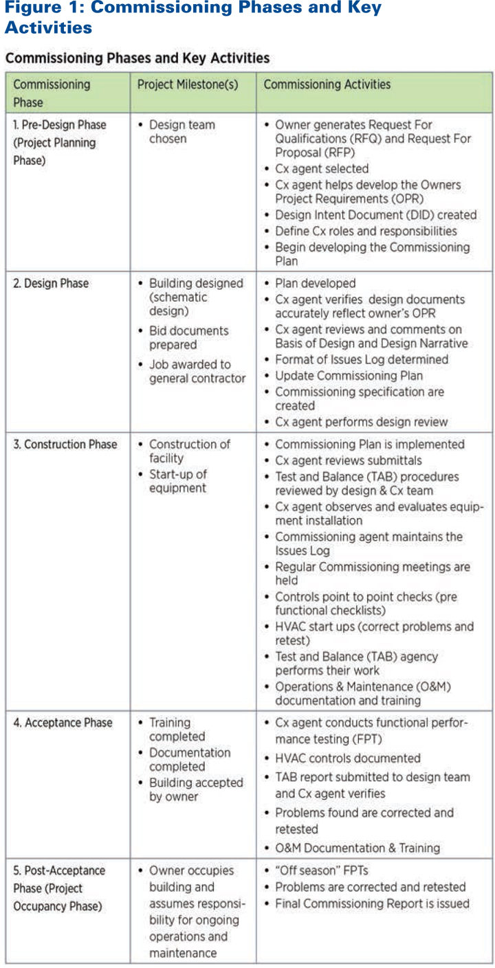
Commissioning a new building is a 5-step process that includes key activities in each phase of the project. A description of the activities associated with each commissioning phase is shown in Figure 1. A more thorough, detailed explanation of the activities associated with each commissioning phase can be found in several documents referenced in the Department of Energy Building Technologies Program’s Guide to Building Commissioning, including ASHRAE Guideline 0–2005 and the ACG Commissioning Guideline.

Commissioning Deliverables

The key deliverables associated with the commissioning process include:

  • Commissioning Plan
  • Pre-Functional Construction Checklists
  • Functional Performance Test Procedures
  • Issues Logs
  • Final Commissioning Report

These are not the only deliverables to be expected from the Commissioning Agent, though. Other important deliverables include a thorough review of the OPR, design documents, submittal documents, and O&M manuals with comments provided to the team for consideration; commissioning progress reports; commissioning meeting minutes; systems manuals; O&M training verification; and a warranty review report.

Final Commissioning Report

The Commissioning Agent is responsible for preparing and submitting the final commissioning report to the owner and the design team. The final commissioning report is a critical document that summarizes the commissioning effort and evaluates whether all of the commissioned systems meet the specifications in the OPR. It should include:

  • A written narrative of the Commissioning Agent’s assessment of each of the commissioned systems’ compliance with contract documents and the OPR, as well as any unresolved commissioning issues
  • A commissioning plan
  • Functional tests
  • All commissioning reports and reviews
  • Issues logs
  • All major communications such as emails, memos, and letters

Building Your Commissioning Team

Commissioning is a team effort that requires effective communication, coordination, and cooperation between all of the parties involved with the project. The Commissioning Agent leads the team. Not all of the commissioning team members will be involved in each phase of the project. However, all should be fully engaged in the activities they are contractually required to perform.

Commissioning Agent—Commissioning Agent, Commissioning Authority, and Commissioning Provider are used interchangeably to represent the person(s) who will be providing the commissioning services.

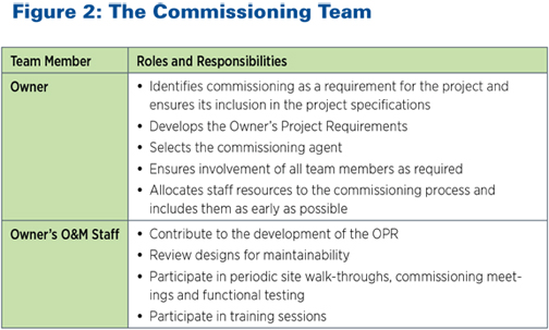
Owner—The owner’s contribution to the commissioning process is vital to the success of every project. One of the owner’s primary responsibilities is to clearly communicate expectations about how the building should operate, as defined in the OPR. It is also imperative that commissioning specifications are included in the design documents and reviewed by the owner. Failure to do so will result in a change order for additional commissioning services. The owner needs to be a strong advocate of the commissioning process, motivating the entire team to actively participate by supporting both the Commissioning Agent’s responsibility to identify issues and the rest of the team’s responsibility to resolve them.

Facility Manager and O&M Building Staff—The Facility Manager and O&M building staff are also important members of the commissioning team. Both can benefit if engaged in the commissioning process as early as possible. In pre-design, the Facility Manager should contribute to the development of the OPR. In the design phase, the Facility Manager can contribute to the design based on experience that can improve the staff’s ability to operate and maintain the building and equipment. Contributions may include modifications to control point naming conventions, graphic layouts of the energy management system, system choices, equipment layout, and other factors that affect maintainability.

By participating in the commissioning process, building staff will gain an understanding of the building’s systems and their interactions well in advance of tenant turnover and occupancy. Observing functional tests and participating in training provided by the contractors and the Commissioning Agent will improve the staff’s understanding of equipment and control strategies.

Summary

Building commissioning is a valuable tool that can and should be used to ensure buildings operate at maximum efficiency. Doing so can not only prevent significant future issues from developing, but can save a tremendous amount of energy and money by ensuring each aspect of the building is performing properly.

SIDEBAR 1

Hidden Costs of Not Commissioning

Two buildings analyzed in detail found that almost half of the deficiencies identified during commissioning would in the future manifest as higher repair and maintenance costs. Similarly, about 1 in 10 deficiencies would have resulted in shortened equipment life, adversely impacted occupant productivity, or increased energy costs. 7

SIDEBAR 2

The Bottom Line

Commissioning improves a building’s asset value. Properly functioning buildings with reliable equipment kept in good condition are worth more than uncommissioned buildings.

  • Commissioned systems and equipment retain their value longer.
  • There is a higher demand for comfortable, healthy, working space that promotes productivity.
  • Systems that function properly use less energy, experience less downtime, and require less maintenance, which save building owners money. 11

References

  1. “Energy Efficiency Factsheet: Building Commissioning for New Buildings,” EnergyIdeas Clearinghouse, Washington State University Extension Energy Program and the Northwest Energy Efficiency Alliance, October, 2005. (http://cru.cahe.wsu.edu/CEPublications/wsueep98-018/wsueep98-018.pdf).
  2. Ibid.
  3. “California Commissioning Guide: New Buildings,” California Commissioning Collaborative, 2006. (http://www.cacx.org/resources/documents/CA_Commissioning_Guide_New.pdf).
  4. Ibid.
  5. Overton, David: “Building Commissioning 101.” Presentation Provided by the Building Commissioning Association (BCA). (http://www.aeesoc.org/pdfs2013/BCxA%20-Cx-101-20131113_nov_14.pdf).
  6. “Building Commissioning: The Key to Quality Assurance,” U.S. Department of Energy. (http://www.pbeeep.org/assets/downloads/BuildingCommisioning.pdf.)
  7. Mills, Evan, Ph.D., “Building Commissioning, A Golden Opportunity for Reducing Energy Costs and Greenhouse Gas Emissions,” Prepared for California Energy Commission Public Interest Energy Research (PIER), July 21, 2009. (http://cx.lbl.gov/documents/2009-assessment/LBNL-Cx-Cost-Benefit.pdf).
  8. See note 7.
  9. Mills, Evan, “Commissioning: Capturing the Potential,” ASHRAE Journal, February 2011. (http://evanmills.lbl.gov/pubs/pdf/ashrae-commissioning-mills.pdf).
  10. Mills, 2009.
  11. “Commissioning for Better Buildings in Oregon,” Prepared by PECI for Oregon Office of Energy, March 1997. (http://www.oregon.gov/ENERGY/CONS/BUS/comm/docs/commintr.pdf?ga=t).
  12. U.S. General Accounting Office, Health, Education, and Human Services Division. Conditions of America’s Schools. Document# GAO/HEHS-95-61, Report B-259307; February 1995. (http://www.gao.gov/archive/1995/he95061.pdf).
  13. “California Commissioning Guide: New Buildings,” California Commissioning Collaborative, 2006. (http://www.cacx.org/resources/documents /CA_Commissioning_Guide_New.pdf).


These excerpts were reprinted from “A Guide to Building Commissioning,” which was released by the Department of Energy’s Building Technologies Program. The report was prepared by Michael Baechler and John Farley, PE, LEED AP, CxA. The full text of the report can be found at www.pnnl.gov/main/publications/external/technical_reports/PNNL-21003.pdf.

Figure 1
Figure 2

Copyright Statement

This article was published in the January 2014 issue of Insulation Outlook magazine. Copyright © 2014 National Insulation Association. All rights reserved. The contents of this website and Insulation Outlook magazine may not be reproduced in any means, in whole or in part, without the prior written permission of the publisher and NIA. Any unauthorized duplication is strictly prohibited and would violate NIA’s copyright and may violate other copyright agreements that NIA has with authors and partners. Contact publisher@insulation.org to reprint or reproduce this content.

For many individuals, preparing their homes for
colder winter weather is an annual event that often includes a variety of
maintenance and winter–proofing activities. There are 2 basic objectives for
preparing a house for winter: make the house more energy efficient, and ensure
it is comfortable during the cold winter months. For a multi–story high–rise, a
commercial building, or an institutional building, the objectives are nearly
the same: make the building more energy efficient and more comfortable for the
occupants.

Unfortunately, the inspection
and maintenance of mechanical insulation is often neglected, leading to both
energy waste and discomfort for building occupants. While it is important to
maintain a mechanical insulation inspection plan year–round, it is particularly
important in the winter, when the temperature drops and there is an increased
chance for high wind gusts and other potentially damaging weather occurrences.

To appreciate the importance of
preparing a building’s insulation for winter, it is useful to consider exactly
what mechanical insulation accomplishes for hot service pipe and equipment. For
example, 2 to 3 inches of conventional pipe insulation on a 380°F steam pipe
reduces heat loss by 93% to 95%. That is the equivalent of reducing heat loss
to approximately 15 to 20 times less than an uninsulated pipe. Thus, relatively
small areas of bare pipe surface, or pipe surface with damaged insulation, can
result in enormous heat losses in a boiler room, mechanical room, or pipe
chases in a building. These heat losses result in energy waste that leads to
financial loss from money spent on extra fuel; excess greenhouse gas emissions;
and high air temperatures in boiler rooms, mechanical rooms, and utility
tunnels. With such clear benefits—or losses—in the balance, it makes sense to
take steps to prepare for winter.

First Step: Insulation Survey

Consider a
dormitory or classroom building at a university and include mechanical
insulation in the list of activities for winterizing the building. Where does
one start? For the purposes of this discussion, assume that the campus has a
central steam plant, with tunnels carrying the steam to each building. Each
building, in turn, has its own mechanical room and steam distribution system.

In such a case, the steam for
heating has been shut down for approximately 6 months over the late spring,
summer, and early fall. After this hiatus, an inspector is likely to find
missing insulation on gate valves, flanges, pressure relief valves, and other
pipe components. Additionally, one might find that some of the straight pipe
insulation has been damaged if other maintenance workers have used the
insulated pipes as stepping pads to gain access to pipes or wires located
higher in the mechanical room. If removable/reusable blankets have been used to
insulate the components, some of those may be laying on the floor, draped over
a pipe, or simply missing. Duct insulation may likewise have been stepped on
and crushed.

Inspectors should first make a
list of the damaged or missing mechanical insulation sections. At each site,
this might include the location of the deficient insulation; size of the pipe
or duct; system description (such as hot air supply, hot steam supply, etc.);
type and thickness of insulation on adjacent pipe; extent of missing or damaged
insulation; and any other relevant information. With this information, an
inspector may use what he or she learned from the National Insulation Association’s
(NIA’s) Insulation Energy Appraisal Program (IEAP), if applicable, to generate
an estimate of the energy wasted by ignoring the problems, the cost of that
wasted energy, and the excess carbon dioxide generated from emissions (see
sidebar on the IEAP on page 8).

Setting Priorities

If insulation
needs to be replaced or repaired, the building owner will have to pay for new
materials and labor costs. Going back to the university example, if the campus
Facilities Manager or Maintenance Manager has been properly educated on the
value of mechanical insulation, he or she may generate work orders to get all
the deficiencies corrected before the boilers are fired up for the fall. While
this is the ideal scenario, it is often not the case.

One way to encourage building
owners to maintain mechanical insulation is to perform a mechanical insulation
survey to estimate both the energy saved and the cost of correcting the
mechanical insulation problems. Typically, the pay–back period will be less
than 4 years and, in the case of 380°F (or hotter) steam systems, it will
probably be closer to 6 months. Making building owners aware of the uniquely short payback period of insulation may help place
repair and replacement of damaged or missing insulation on a high–priority
list. Short of shutting the building windows and doors, almost no other measure
has a shorter energy payback. In regard to the value of energy savings in most
institutional buildings, fixing missing or damaged mechanical insulation on hot
service pipes and ducts is the easiest measure, with the most significant
rewards.

In arguing the case for winterizing a building by repairing or replacing
damaged or missing mechanical insulation, it may also be useful to talk about
the thermal comfort of the building occupants. Cold buildings may lead to
complaints, which can cause difficulties for management as well as the
facilities and maintenance staff. After all, the main purpose of heating many
commercial buildings is to keep the occupants comfortable. In other applications,
heating can be a health and safety issue—consider, for example, a mechanical
room with a 120°F air temperature, along with hot steel surfaces. This is an
unsafe work environment for all maintenance craft laborers due to heat stress
and the danger of burn injuries. Building owners also must consider whether
they are up to date with current energy codes. If insulation is missing or
damaged, or the codes have changed, the building may no longer be compliant.

Executing the Work

It is important to remember that one of the reasons
for missing mechanical insulation is that mechanical maintenance personnel may
have removed it to do their work (such as replacing seals in pumps and valves,
replacing gaskets in flange pairs, draining strainers, etc.). To prevent damage
to newly installed insulation, all mechanical maintenance work scheduled for
the fall should be completed first, and the heating system should be tested for
leaks. All mechanical insulation work should be coordinated with the mechanical
maintenance crew to eliminate the possibility of one project interfering with
another. It is advisable to write a checklist for the insulation work and
establish an insulation maintenance schedule. Finally, to keep matters in
perspective, it is recommended to have an estimate of energy savings, insulator
labor cost, and insulation material cost for the proposed work.

After Finishing the Winterizing Work

After the insulators have finished the work of
repairing or replacing damaged or missing insulation, a staff person from the
facilities department should conduct a visual inspection using a checklist. It
is also advisable to turn on the boiler and measure the room’s air temperature
after several hours to verify that it is within reasonable limits. If it is
not, there may still be hot, bare surfaces on the heating system pipes. Lastly,
a member of the maintenance staff should write a final report to document and
justify the work that has been done, as well as to lay the groundwork for doing
the same evaluation a year later. While, ideally, no mechanical insulation will
need to be repaired or replaced the following year, that may be the case for
some facilities.

Preparing for the Summer Cooling Season in Early
Spring

Hopefully, after the Facilities/Maintenance Manager
has successfully prepared a building’s insulation system for winter, the
building owner will be on board with following the same preparation in the
spring for the cooling system. The process starts with evaluating the chiller
insulation and the chilled water pipe insulation. The incentive to do this is
not only to prevent energy waste and ensure thermal comfort, but also to
prevent water vapor condensation.

Before long, it will be time to
repeat the cycle once again for winter.

SIDEBAR

Energy Audits Can Save Money

One
of the best ways to fully understand the benefits of fixing missing or damaged
insulation is to do an insulation energy appraisal. NIA offers an Insulation
Energy Appraisal Program (IEAP), which can help insulators learn the skills
they need to complete these appraisals. The IEAP program consists of a 2–day
course that teaches students how to determine the optimal insulation thickness
and corresponding energy and dollar savings for a project. The program was
designed to teach students the necessary information to give facility/energy
managers a better understanding of the true dollar and performance value of
their insulated systems. To give facility managers the most accurate
information, students will gain skills in the following areas:

  • Conducting a facility walk–through

  • Interviewing customers

  • Using the 3E Plus® version 4.0 software

  • Determining the amount of greenhouse gases saved
    through the use of insulation

  • Analyzing and completing the appraisal spreadsheet

  • Completing and presenting a final customer report

Students
who pass the course exam—certified by the National Inspection Testing
Certification Corporation—will become Certified Insulation Energy Appraisers.
The certification will be valid for 3 years, after which the individual must
recertify. It is an invaluable distinction that can help give insulators a
competitive edge and help grow their business.

For
more information, visit
www.insulation.org/training or email training@insulation.org.

Figure 1

As this photo shows, some of the duct wrap insulation on the underside of this duct has become damaged and/or detached from the duct. This insulation should either be repaired or replaced in preparation for the winter heating season.

Figure 2

In this application, some pipe insulation is missing and needs to be replaced before firing up the boilers for winter. Some of the remaining pipe insulation clearly needs to be either replaced or repaired. Replacement with new material may be quicker and easier than trying to repair the old insulation.

Figure 3

Most insulation professionals have seen pipe insulation damaged by foot traffic. These pipes are located close to ground level and have a high likelihood of being stepped on, resulting in damaged insulation. This damaged insulation should be replaced by new material before firing the boilers for the winter. It some cases, it may be prudent to use a hard, high–compressive strength insulation that can better withstand foot–traffic abuse.

Figure 4

This bare gate valve in a steam tunnel at a university results in excessive heat loss and high air temperatures in the tunnels. It should be insulated with either conventional insulation or with a removable/reusable insulation blanket as part of the process of preparing campus buildings for winter.

Figure 5

Preparing a spreadsheet such as the one above that summarizes the value of the energy savings, the simple payback, and the annual tons of greenhouse gas emissions reduction will help a facilities department get funding for their insulation project. With a simple payback of only 6 months (typical for a steam heating system with 380°F steam), the case for doing this maintenance work on the pipe insulation is compelling. (Note: 3E Plus® was used to calculate the heat flux values, not shown on this summary table).

Figure 6

On components such as this pressure regulator on a steam pipe, it may be prudent to use a removable/reusable insulation blanket. Mechanics may have removed this blanket assembly to perform necessary maintenance. However, it must be reinstalled by a skilled, knowledgeable insulator for it to insulate properly. Autumn is the best time to accomplish this.

Figure 7

This strainer and its connecting flanges should be insulated, and this work should be accomplished prior to the start of the heating season. Likewise, the butterfly valve to its right should be insulated. Leaving these 2 components bare will result in significant energy waste during the heating season and will contribute to a high–temperature boiler or mechanical room.

Figure 8

Every repaired pipe insulation project is not necessarily going to look this good. In this application, the strainer should be insulated, perhaps with removable/reusable insulation blankets, as well as portions of the 2 steam pressure regulators. It would also be beneficial to insulate the gate valve bonnets and steps, since those result in exposure of considerable amounts of bare steel that lose a great deal of heat.

The connection between
energy and water, often referred to as the “energy-water nexus,” is collecting
attention from business leaders, policy makers, and citizens alike. In short,
this term refers to the close link between water and energy. Water is used in
nearly every aspect of energy production. Saving energy will save water, and
saving water will save energy. When we consider that the demand for electricity
is expected to increase significantly in coming decades, it is clear that water
consumption will also increase. This links adequate water supply directly to
the energy security of our country. Clean energy technologies such as biofuels
and carbon sequestration actually require large amounts of water to produce; so
while they cut down on greenhouse gas emissions, they may actually contribute
to water pollution and waste. Wind and solar power are the cleanest energy
sources in terms of both water and carbon emissions.

Electricity,
in particular, has a significant impact on our water supply. Fossil fuel
generation, nuclear power, and hydroelectricity all consume large amounts of
fresh water. It is estimated that fossil fuel generation alone represents about
39% of all fresh water withdrawals in the United States, which equals about 136
billion gallons of water per day. When you do the math, it turns out that every
single kWh of electricity uses about 40 gallons of fresh water. Water is also
used intensively for extracting the fuels that generate our electricity. Coal,
oil, and natural gas all require a significant water supply to acquire and, in
most cases, contribute to fresh water pollution. Hydraulic fracturing, or
“fracking,” is one of the most controversial topics currently circulating in
the energy sector. It is a hot topic because chemicals are mixed with water and
injected into rock to release gas or oil. There is still debate over whether or
not this practice seriously contributes to pollution of the water table.

On
the other hand, clean water has a sizeable footprint when it comes to
electricity. Electric power is used to treat and pump water supply to homes and
businesses. In fact, the water industry consumes about 100 million MWH of
electricity per year. This is equal to about 4% of all generated power, and
most of that energy is used by water pumps. The interconnection between water
and energy means that conserving one will help conserve the other. By becoming
more energy efficient, we become more water efficient, and vice versa.

As
energy efficiency and smart grid initiatives are more commonly adopted across
the world, similar solutions to the problem of water efficiency may follow
suit. The fact is that electricity demand in the United States is rising,
especially in regions typically strained for water supplies, such as the
Midwest, which experienced serious drought last year. This means water supplies
will need to be conserved as much as possible going forward and one way to help
this happen is to become more energy-efficient.

The
energy-water nexus reminds us that our resources are not isolated. We often do
not remember how reliant we are on a good water supply. Water and energy also
both contribute to the operating expenses of business and industry. Enacting
energy conservation methods in these sectors not only conserves resources, but
can save money as well.

SIDEBAR

Insulation’s Importance in
the Energy-Water Nexus

The
energy-water nexus refers to the inextricable link between water and energy,
due to the fact that water is used to obtain and produce energy, and energy is
expended in the delivery of water. Insulation is so often mentioned in
energy-water nexus discussions because it offers the opportunity to conserve
these valuable resources. According to the National Institute of Building
Sciences (NIBS) “more, not less, insulation?” is essential to enhance the
long-term performance of building systems. Studies indicate that pipe
insulation reduces the amount of time needed for water—at the desired temperature—to
reach the end user. This conserves water and, in the case of hot water, saves
energy. This leads to lower costs as well as less energy and water waste; it is
a simple technology that can lead to immense savings. Policy makers and
business leaders are taking note of energy-water nexus issues, and upcoming
building codes and plans are likely to reflect updates to conserve energy and
water. This may present increased opportunities for insulation professionals as
building plans include the use of more insulation. Buildings with better
insulation systems not only provide tremendous financial savings for building
owners and tenants, they can also reduce environmental impact by increasing
efficiency. Insulation has the potential to help solve these energy, financial,
and environmental issues—a fact that will continue to garner attention and
concrete benefits for those in the industry.