Summary
The outlook for the construction market in 2024 is decidedly mixed as contractors predict transitions in demand for projects, the challenges they will face, and the types of technology they will embrace. Amid these changes, however, contractors are still struggling to cope with significant labor shortages, the impacts of higher interest rates and costs, and a supply chain that, while better, is still far from normal.
Demand for different types of projects is changing. Respondents to this year’s Construction Hiring and Business Outlook Survey (Outlook) are less confident about growth prospects for many market segments than they were a year ago. They are most optimistic about a range of public-sector market segments, including water and sewer projects, transportation, federal, and bridge and highway work. Conversely, they predict private sector demand will be less robust for segments such as manufacturing and multifamily residential and will decline for lodging, retail, and private office construction.
Contractors have also tempered last year’s high expectations for new federal investments in infrastructure and other construction projects. Nowhere did contractors’ expectations for growth in a market segment drop more between last year and this year than in the highway and street and other transportation construction segments. Relatively few firms report having picked up work because of new federal investments in 2023. A growing number of firms likely have found that the federal review process and complex new Buy America rules associated with these projects are limiting the benefits of the federal funds.
While contractors remain mostly upbeat, their top worries for 2024 include fears about the impacts of higher interest rates on demand for construction and the risk that the economy could enter a recession. In addition to these new worries, contractors continue to be concerned about workforce shortages and their impacts on construction prices and schedules. And they continue to see projects being delayed—sometimes indefinitely—because of rising costs, slower schedules, and shrinking demand for the finished products.
Perhaps because of the challenges they face, contractors plan to invest in new technologies that promise to make their operations more efficient and productive. Many firms report they will make new or continued investments in drones, artificial intelligence tools, and off-site production. Many will also continue investing in information technology (IT)tools to make their accounting, project management, and other functions more efficient. But even as firms make these investments, many worry that they lack the time and personnel to properly implement and train for these new technologies.
In other words, 2024 offers a mixed bag for construction contractors. On one hand, demand for many types of construction should continue to expand. And firms will continue to invest in the tools they need to be more efficient, productive, and profitable. Yet contractors are less enthusiastic about most market segments than they were at the start of 2023. Meanwhile, they face significant challenges when it comes to finding workers, coping with rising costs, and weathering the impacts of higher interest rates.
If Washington can get out of its own way in moving infrastructure projects forward, if the Federal Reserve can successfully manage the “soft landing” it has been pursuing, and if the industry can find a way to successfully recruit and retain more workers, 2024 should be a good year for most construction firms. AGC will do everything in its power to make sure those “ifs” turn into “whens.”
Contractors Expect Demand for Projects to Increase but Are Less Confident than a Year Ago
On balance, contractors remain upbeat about the available dollar value of projects to bid on in 2024. But the optimism regarding opportunities for most project types is less widespread than it was a year ago.
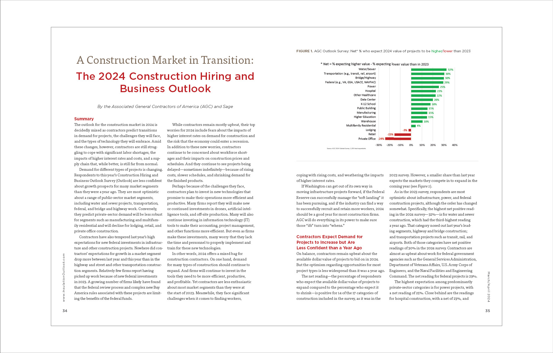
The net reading—the percentage of respondents who expect the available dollar value of projects to expand compared to the percentage who expect it to shrink—is positive for 14 of the 17 categories of construction included in the survey, as it was in the 2023 survey. However, a smaller share than last year expects the markets they compete in to expand in the coming year (see Figure 1).
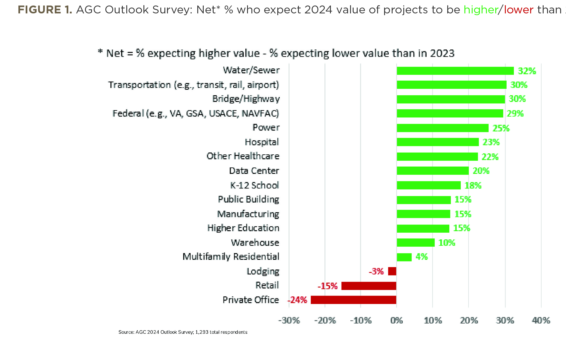
As in the 2023 survey, respondents are most optimistic about infrastructure, power, and federal construction projects, although the order has changed somewhat. Specifically, the highest net positive reading in the 2024 survey—32%—is for water and sewer construction, which had the third-highest reading a year ago. That category nosed out last year’s leading segments, highway and bridge construction; and transportation projects such as transit, rail, and airports. Both of those categories have net positive readings of 30% in the 2024 survey. Contractors are almost as upbeat about work for federal government agencies such as the General Services Administration, Department of Veterans Affairs, U.S. Army Corps of Engineers, and the Naval Facilities and Engineering Command. The net reading for federal projects is 29%.
The highest expectation among predominantly private-sector categories is for power projects, with a net reading of 25%. Close behind are the readings for hospital construction, with a net of 23%, and non-hospital health-care facilities, such as clinics, testing facilities, and medical labs, with a net of 22%.
The largest increase in optimism from the previous survey is for data center construction, with a net positive reading of 20%. That is up from 12% a year ago.
On balance, contractors are optimistic, as well, about the education sector. The net reading is 18% for K–12 schools and 15% for higher education construction.
Three other segments have readings that are positive, on net, by double-digit percentages. The net reading for both public buildings and manufacturing construction is 15%. The net is 10% for warehouses.
In addition, there are four market segments for which respondents are closely divided between favorable and unfavorable outlooks or have negative expectations on balance. There is a net positive reading of 4% for multifamily residential construction. Expectations are bearish for lodging, with a net negative reading of -3%, retail construction at -15%, and private office construction at -24%.
Despite the largely positive net readings, fewer respondents are confident about growth prospects than they were a year ago. The net reading decreased from the 2023 survey for nine project types, increased for six types, and remained unchanged for two— hospitals and warehouses.
The steepest downturn in expectations occurred with transportation and bridge/highway construction, both of which recorded declines of 12 percentage points from the net readings in the 2023 survey. The net readings for public building and federal construction both slid 8 percentage points. In contrast, the largest upswing in net readings is 8 percentage points—for data center construction—while there were only small upturns for the other five categories that have higher net readings than a year ago.
The Bipartisan Infrastructure Law Will Make a Difference but Not Yet
The decline in optimism regarding infrastructure projects may be because few contractors report having been awarded projects that received funding from the federal Bipartisan Infrastructure Law, even though it was enacted more than 2 years ago in November 2021. Indeed, only 9% of respondents say they have worked on new projects funded by the law, while 6% have won bids but have not started work. Seven percent say they have bid on projects but have not won any awards yet, whereas 12% plan to bid on projects but say nothing suitable has been offered yet.
Hiring Expectations Are High but So Are the Obstacles
Most firms anticipate adding workers in 2024 to accommodate the higher demand for projects. More than two-thirds (69%) of the respondents expect to add to their headcount, compared to only 10% who expect a decrease. While just under half (47%) of firms expect to increase their headcount by 10% or less, nearly one-quarter anticipate larger increases. Eighteen percent of respondents say their headcount will grow by 11–25%, and 4% of respondents anticipate an increase in headcount of more than 25% (see Figure 2).
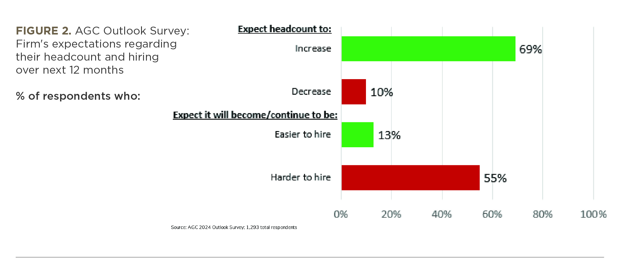
However, respondents expect difficulty adding workers—a situation that has changed little over the past year. Seventy-seven percent of respondents report they are having a hard time filling some or all salaried or hourly craft positions, close to the 80% who reported difficulty in the 2023 survey. Only 10% say they are having no difficulty. (The rest have no openings.) In addition, the majority (55%) expects that hiring will continue to be hard (35%) or will become harder (20%). Only 13% say it will become easier or remain easy to hire, while 31% expect no change.
Union and open-shop firms have similar expectations about expanding their headcount and the difficulty in doing so. For both types of firms, 70% of respondents expect their companies will add to their headcount in 2024. Both types of firms report difficulty filling positions: Only 7% of open-shop respondents and 9% of union respondents report no difficulty filling any salaried or hourly craft positions.
A large majority of firms took steps in 2023 to attract and retain workers. Sixty-three percent increased base pay rates more than in 2022. Additionally, 25% of firms provided incentives or bonuses, and 24% of the firms increased their portion of benefit contributions and/or improved employee benefits. Only 9% of firms provided no increases in pay, incentives, or benefits in 2023.
In general, there is little variation by region among contractors’ responses, but firms in the South are somewhat more likely than in other regions to have offered steeper pay increases to attract and retain workers. Nearly two-thirds (66%) of firms based in the South increased base pay rates in 2023 more than in 2022, compared to 64% of firms in the Midwest, 61% in the Northeast, and 58% in the West.
Rising Costs and Interest Rates Are Causing Postponements
As in the past two surveys, nearly two-thirds of respondents say projects have been postponed or canceled. Almost equal percentages of firms report projects were postponed or canceled in 2023 and not rescheduled (36% of respondents) as report projects were postponed but rescheduled (37%). Ten percent have already experienced postponement or cancellation of a project that had been scheduled for the first half of 2024.
More than half (53%) of firms say a project was postponed or canceled due to rising costs (for construction, insurance, etc.), while 38% of firms cite rising interest rates as a cause of deferrals. In addition, 34% cite reduced funding availability. Delays in likely completion dates and reduced demand for completed projects are each listed as reasons for deferral by 11% of respondents.
Supply-Chain Problems Have Diminished, Not Disappeared
Although only 23% of respondents say they have not had any significant supply-chain problems, that is a marked improvement over the previous two surveys, when only about 10% of respondents said they had had no problems. To cope with problems, 56% of respondents have accelerated purchases after winning contracts, compared to 70% in the 2023 survey. Forty-five percent have turned to alternative suppliers, compared to 56% in the 2023 survey. Thirty-six percent have specified alternative materials or products, compared to 49% a year ago. And only 14% have stockpiled items before winning contracts, down from 22% a year earlier.
Despite the overall improvement in the supply chain, more than 140 respondents took the trouble to list specific items or categories with problems. By far, the most frequently mentioned issues are with electrical items such as panels, transformers, and the switchgear used to control, protect, and isolate electrical equipment. Numerous contractors also mentioned heating, ventilation, and air conditioning equipment.
Top Concerns Include Interest Rates, Worker Supply, and Recession
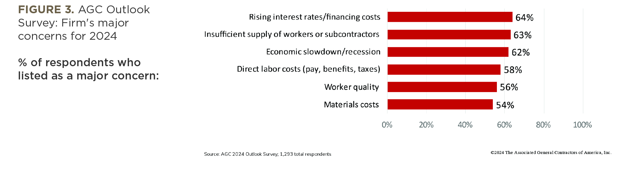
Three concerns top contractors’ lists of worries about 2024. Sixty-four percent pick rising interest rates/financing costs as one of their biggest concerns, while 63% list insufficient supply of workers or subcontractors, and 62% name economic slowdown/recession. (Respondents were offered 22 choices, along with the chance to write in other answers. They could list multiple “biggest concerns.”)
Three industry-specific concerns are cited by a majority of respondents: Fifty-eight percent list rising direct labor costs (pay, benefits, employer taxes), while 56% pick worker quality, and 54% list materials costs.
Most of these concerns are cited less often in the 2024 survey than a year ago. The biggest change is in the share of respondents listing project delays due to availability/supply-chain issues: 34% this year, compared to 63% in the 2023 survey (see Figure 3).
Besides worrying about worker quality, 81% of firms view inexperienced skilled labor or workforce shortage as a challenge regarding the safety and health of their workers. Among seven listed challenges regarding worker safety and health, the next-most frequently cited (by 36% of respondents) is mental health challenges for workers. In addition, 25% cite poor subcontractor safety and health performance. Twenty-three percent of respondents point to unclear or unworkable government regulations, and 22% cite safety hazards created by third parties such as motorist crashes into work zones. Twenty percent pick unreasonable inspection or enforcement of government rules as a challenge regarding the safety and health of their workers.
Contractors Plan to Invest in Drones, Artificial Intelligence, and Off-Site Production
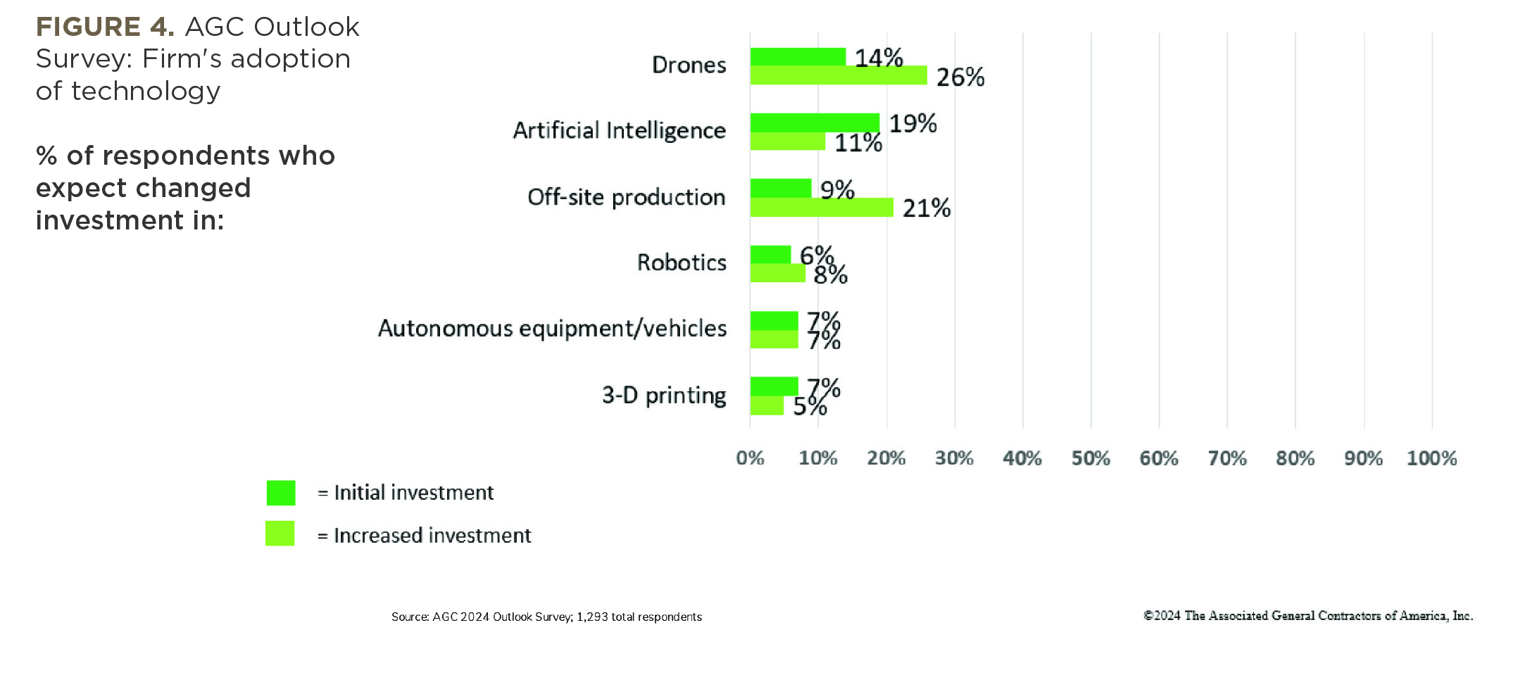
Construction firms have been seeking ways of adapting to the shortage of skilled workers and improving jobsite safety and productivity. In particular, nearly 40% of firms say they will either increase their investment in drones (26%) or make an initial investment (14%). Thirty percent of firms will make an initial investment in artificial intelligence (19%) or increase their investment (11%). And almost 30% plan to make more use of off-site production (21%) or start to use it (9%).
In contrast, few firms expect to invest in robotics (15%) or autonomous equipment/vehicles (14%). Even fewer firms—12%—are ready to invest in 3-D printing (see Figure 4).
The most likely candidates for increased software spending are accounting software and project management software—for each type, 38% of respondents expect to increase their investment. Close behind is document management software, cited by 36% of firms. Thirty-one percent plan to increase spending on estimating software. All of these
percentages are higher than in the 2023 survey.
Firms list numerous ways in which they plan to use mobile software technology, while only 8% report having no plan to use it. Two-thirds of respondents (67%) say it would be used for daily field reports. More than half of respondents pick employee time tracking and approval (59%); access to customer and job information from the field (58%); and sharing of drawings, photos, and documents (54%). Other widely cited uses include access to job cost and project reports from the field (48%), punch lists and scheduling (42% each), and equipment tracking (41%).
Firms use cloud-hosted IT in various ways. The most prevalent use is in project management, cited by 58% of firms. Nearly half list accounting (48%) and field operations (47%), while time tracking is noted by 46%. However, only 17% list tool management, while 20% say they do not use the cloud. These percentages are little changed from the 2023 and 2022 surveys.
Among the biggest IT challenges noted by firms, three stand out. Forty-three percent of contractors say it is difficult to find the time to implement and train on new technology. Forty-two percent of firms mention keeping company data secure from hackers, while 41% cite employee resistance to technology. In addition, 35% point to connectivity to remote job sites as among the biggest challenges, and 33% list communication between the field and office.
Conclusion
Contractors remain mostly upbeat about the construction industry’s prospects for 2024. They expect demand to grow for most market segments. Most firms plan to add new staff and to make new or
continued investments in IT. A growing number of firms are embracing new technologies like drones and artificial intelligence. And they are investing
in ways to build more efficiently via off-site
prefabrication.
Yet contractors are less optimistic at the start of this year than they were 12 months ago. Their expectations for massive new federal investments in infrastructure and construction have come down. They expect demand for retail, office, and lodging construction to contract this year. They continue to struggle with labor shortages and are increasingly worried about the impacts of high inflation rates and the risks of the economy entering a recession. In other words, there are enough challenges that the year may not end up being as positive as expected.