Category Archives: Global

Cooper’s Hawk Winery & Restaurant was founded in 2005 by CEO Tim McEnery. This project was built upon his conviction that food and wine can create lasting memories and facilitate special moments for patrons. The first restaurant opened in Orland Park, Illinois, and they have opened dozens of other restaurants across the United States since that initial opening. The overall concept fuses a winery, modern casual restaurant, a Napa-style tasting room, and an artisanal retail market. Each restaurant hopes to create a unique and memorable dining experience for patrons. The restaurant was the first outside of wine country to combine a restaurant winery with a Napa-style tasting room and retail market under one roof.

The establishment also offers the Cooper’s Hawk Wine Club, which is sourced from grapes grown around the world, including Italy, France, California, Chile, New Zealand, and Australia. The wines are exclusively sourced, blended, aged, bottled, and distributed by Cooper’s Hawk.

Of course, this type of commercial building requires a significant amount of insulation. The building includes refrigeration systems, chilled water piping, and normal commercial considerations like duct and HVAC insulation. The equipment and insulation must also be able to undergo frequent wash downs, so properly designed systems with correctly-selected insulation and jacketing, and professional installation are particularly crucial. Since the wines are not created at each location, the insulation needs are similar to other restaurants. In addition to the normal requirements for chilled water lines and a commercial HVAC system, these restaurants have additional refrigeration needs. They need to refrigerate food and have temperature-controlled lines at the bar for both beer and a unique wine storage system. They also need to maintain temperature control over select bottles of both red and white wines.

The chain recently built a new location next to NIA’s Headquarters in Reston, Virginia. NIA staff has been fortunate enough to watch the construction progress and speak with Walter Fisher, Cooper’s Hawk Vice President of Design, Construction, and Facilities. He said, “Cooper’s Hawk Winery and Restaurant is always committed to using quality materials and products. From insulation and other building materials all the way through to grapes we use and food we serve. Our goal is to deliver the best experience to the guest in all of our communities, including our newest location in Reston. We hope everyone enjoys our beautiful design, award-winning wines, and our great food—but most of all the atmosphere and people that will be taking care of you.”

The insulation system design for this project included a mixture of Extruded Polystyrene Foam (XPS) for the building envelope. elastomeric; duct insulation; high temperature, fire-rated mineral fiber; and PVC jacketing are commonly used for these types of mechanical systems. The unique needs of the wine chain and the need to clean for food preparation led to the selection of these materials.

Cooper’s Hawk Restaurants favor California wine country architecture and can accommodate approximately 300 guests. The award-winning chain offers a paired wine suggestion with each menu item, and everything is made in the restaurant’s kitchen with a focus on including seasonal ingredients. The menu features contemporary American food with 110 dishes with flavors from all over the world. Patrons who step into the tasting rooms at the restaurant may not notice the insulation systems, but its ability to maintain a comfortable temperature will surely enhance their appreciation of fine wines.


Copyright Statement

This article was published in the October 2017 issue of Insulation Outlook magazine. Copyright © 2017 National Insulation Association. All rights reserved. The contents of this website and Insulation Outlook magazine may not be reproduced in any means, in whole or in part, without the prior written permission of the publisher and NIA. Any unauthorized duplication is strictly prohibited and would violate NIA’s copyright and may violate other copyright agreements that NIA has with authors and partners. Contact publisher@insulation.org to reprint or reproduce this content.

For more than a century, Faribault Foods has delivered a spectrum of canned goods to consumers, steadily building a brand portfolio that includes household names such as Butter Kernel, Luck’s, Chili Man, and KC Masterpiece. In 2014, the company merged with Arizona Canning Company as a result of being acquired by La Costeña, a Mexican food company, further expanding both organizations’ offerings and capabilities.

As part of its ongoing growth, Faribault Foods began construction of a new plant in Faribault, Minnesota, in 2016. The new facility features faster, more efficient production lines and a can-production line. It expanded the size of the Faribault complex there to nearly one million square feet.

Construction of the new state-of-the-art plant involved evaluating all aspects of materials to deliver a facility that would operate at optimum efficiency—something demanded in the increasingly competitive food industry. Insulation is critically important to these types of facilities. Improper insulation choice can lead to system inefficiencies, energy waste, or even put the system at risk for damage. These systems must undergo frequent wash downs, making it important to choose an insulation that is resistant to moisture, and a jacket that allows for multiple-times-per-day cleanings.

Good Insulation Value without Compromising Moisture Resistance

The Faribault installation was a challenging application. As a food processor, Faribault Foods must comply with strict cleanliness regulations. That means many areas of the facility are subject to hot water wash downs on a routine basis. For food-processing systems, it is important to choose an insulation that can provide moisture and corrosion resistance. This requirement also necessitated that the insulation chosen must be covered with a solvent-welded PVC jacketing system to provide the initial resistance to water and physical impacts from repetitive cleaning. This jacket provides an outer layer to the designed insulation system and increases its moisture-resistance, which is extremely important given the frequent wash downs. The PVC jacket is easy to clean and gives the system a high level of protection.

Water, as always, is insulation’s worst enemy, so Faribault’s design build firm, the Stellar Group, evaluated a number of closed cell insulation products to go under the PVC jacket. “We created a specification and then reviewed several products to see what could meet it,” said Brad Blocker, Project Manager.

Product Selection: EPDM Elastomeric Foam Closed Cell Insulation

The project has above- and below-ambient water systems and below-ambient equipment such as pumps, heat exchangers, vessels, and extensive refrigerant piping. All these systems and pieces of equipment had the same needs: a thermally efficient, highly moisture resistant, long-lived insulation system with a USDA-approved wash-down finish. The installation had to be tightly sealed against moisture intrusion and water vapor intrusion with a high level of attention to detail. The piping and equipment being insulated included regular carbon steel construction and a significant amount of stainless steel construction. It was necessary to use an insulation system that did not contribute to external stress corrosion cracking on stainless steel. This is a highly common concern in most food-processing facilities today, creating a common need for insulation materials that can serve long-term on stainless systems without contributing to a shortened life span of the piping and equipment. “Some of the first products looked at for the project turned out not to offer the necessary performance,” noted Gary Shelberger of Ten Point Marketing, who was also involved in the project. “They could provide part of the performance solution, but not all of it. This was a complex job—there were different sizes of pipe, and there was the sheer volume of pipe that had to be insulated. The insulation had to not only perform, but it had to be easy to install. There were many times when the pipe installation technicians were having to work around other contractors’ schedules. There were lots of stops and starts.”

The insulation product chosen for this project is 38% more thermally efficient than the next most-moisture resistant insulation material. This feature reduced the thickness needed while providing the same insulating protection. When paired with a PVC jacket, it also delivered the water and water-vapor resistance desired for low temperature insulation systems in the food-processing environment and protected the system from efficiency losses. The product was also chosen because it delivers excellent fire safety properties and does not support combustion, having been rated as self-extinguishing, as tested by ASTM D635. It will not support the growth of microorganisms, which eliminates the need for microbicides, as tested by ASTM C1338, G21, and UL181; and also does not contain chlorofluorocarbons (CFCs), hydrofluorocarbons (HFCs), and hydrochlorofluorocarbons (HCFCs), making it safe for use in a wide range of facilities. It is a 99+% closed-cell material that provides no food source for birds or vermin, is stable over a wide range of environmental conditions, and contributes to sustainable building practices, including LEED™ and LBC™.

The Big Challenge: Corrosion under Insulation on Stainless Steel

Another major concern for Faribault Foods and its contractors was corrosion under insulation (CUI). This phenomenon occurs when halogen compounds (compounds of chlorine, bromine, or fluorine) become trapped with moisture under the insulation, corroding even stainless steel piping. There are extensive process piping systems and pieces of equipment in this facility made from stainless steel. In an environment such as a food-processing plant, there is the constant threat of moisture and water vapor entering the insulation system. This is especially true if there is a meat processing or cooking element involved, such as with chili or seasoning meat for beans, which have long process times (compared with vegetables, fruits, and juices) and generate high temperatures and high humidity. High heat with humidity and steam can drive moisture into an insulation system, so the system needs to be very moisture resistant, well-sealed, and easy to clean. Chlorine is one of the most common chemicals used for cleaning wash downs, so the system also needs to be impermeable. This is managed with: (1) Effective sealing of insulation systems, especially at all termination points; and (2) An insulation that contains low-halogen compounds that could react with moisture. In such circumstances, the insulation that will be in contact with stainless steel piping should be tested for meeting the requirements of ASTM C795 and/or C692 to avoid the content of halogen compounds that can leach out when water is introduced, combining with the moisture, and creating a solution that can corrode stainless steel piping.

“There are very low levels of any halogen compounds in this product that could contribute to CUI,” noted Shelberger. “That was a very attractive point for the customer. And the installation system for the [elastomeric insulation] provides positive seals at all points—even product ends—so there is solid confidence in moisture protection.” Greg Newman of Insulation Midwest, the contractor who installed the insulation, also noted that “it doesn’t contain foaming agents that can contribute to pipe corrosion. Something else to consider about EPDM is that it doesn’t crystallize when exposed to hot water—it retains its elasticity.”

These performance characteristics have made EPDM an appropriate option for many below-ambient mechanical systems operating as low as -320°F, including chilled water, retail food case refrigeration, industrial refrigeration applications, glycol, brine, ammonia refrigeration, industrial gases, liquid methane, liquefied natural gas (LNG), and liquid oxygen systems.

More Than Five Miles of Pipe

One of the biggest challenges for the Faribault Foods installation was its sheer size. The plant addition added over 600,000 square feet, making the entire complex nearly 1 million square feet. The entire plant used more than 5 miles of pipe insulation with PVC jacketing and over 20,000 square feet of rolled EPDM insulation. In addition, Project Manager Blocker pointed out that the plant layout had the boiler room and the refrigeration areas more than 800 linear feet apart, so any common pipe elements had to account for this span. This project included well over 5,000 linear feet of pipe used for the boiler/mechanical room only. We were dealing with different sizes and with untold connections and joints.

Installation

The contractors used both pre-slit and unslit elastomeric. The unslit product was used to slide over uninstalled piping. The pre-slit elastomeric used had a positive self-sealing strip that bonded with the EPDM to keep moisture out (remember—there are millions of EPDM membrane roofs installed around the world). Ends were joined with contact cement or a special pressure-sensitive adhesive disc that ensures a solid seal and made installation faster. Pressure-sensitive closures are appropriate for food-processing facilities because there are no fumes or solvent vapors to contaminate products, and it can seal in cold environments. “Installers were able to move quickly and effectively, even when they had to be interrupted because another contractor’s work took precedent. It was easy to pick up where the workers had left off,” said Shelberger.

Conclusion

There are several selection criteria to consider in a project like this. Cost effectiveness and system longevity are major system design considerations for an owner who wants to see process efficiency and temperature regulation continued uninterrupted for the life of the installation. As important as material selection is for this, detail and quality during installation are also key. The expectation of high levels of moisture and water vapor in the environment drives the need for effectively and completely sealed moisture-resistant insulation system components. This sealing requires skilled labor that is highly familiar with the specialized needs associated with these kinds of installations. When a well-designed and -installed system is in place, an owner can see not only a financial return on his investment, but a reward in the system’s reliability.


Copyright Statement

This article was published in the October 2017 issue of Insulation Outlook magazine. Copyright © 2017 National Insulation Association. All rights reserved. The contents of this website and Insulation Outlook magazine may not be reproduced in any means, in whole or in part, without the prior written permission of the publisher and NIA. Any unauthorized duplication is strictly prohibited and would violate NIA’s copyright and may violate other copyright agreements that NIA has with authors and partners. Contact publisher@insulation.org to reprint or reproduce this content.

With any product you purchase, it is important to read the label and product data sheet (and assembly instructions, if any) before you purchase it. The data sheet provides you with the physical properties or specifications of the product, defines where or how the product should be used, and details the expected performance of the product. This, in turn, provides you with the information needed to compare competing products and to take performance differences into consideration when evaluating cost differences. For a simple item like a can of soup, you might be looking at calories per serving, sodium content, and whether the soup is gluten, dairy, or soy free. For a riding lawnmower, you may be considering horsepower, transmission type, cutting-deck width, power or manual steering, turning radius, availability of parts and services, and warranty. If you happen to live in California, you need that riding mower to be emissions compliant as well.

In the case of flexible elastomeric closed cell mechanical insulation, the most widely specified standards called out in North America are ASTM C534: Standard Specification for Performed Flexible Elastomeric Cellular Thermal Insulation in Sheet and Tube Form, and ASTM C1534: Standard Specification for Flexible Polymeric Foam Sheet Insulation Used as a Thermal and Sound Absorbing Liner for Duct Systems. These standards define properties such as thermal conductivity, water-vapor transmission, shrinkage, service-temperature range, etc. Life-safety properties like flame spread and smoke developed ratings (also referred to as surface-burning characteristics) are also defined. Each of these properties is determined according to a specific test method, but for many properties, multiple standardized test methods are available and used.

The ASTM standards also establish minimum performance criteria for each of the defined properties. The manufacturer’s data sheets can be used to determine if a product meets the minimum criteria necessary to conform to the applicable standard. The typical insulation product data sheet (or data submittal sheet) also includes information regarding recommended uses and code compliance so that a prospective mechanical engineering specifier or end user can determine whether the specific product is suitable for a particular application (i.e., will it perform to expectation and will it conform to any applicable building codes?). While we are using flexible elastomeric insulation as an example, it is important to note that any insulation product manufactured domestically has an ASTM standard associated with it.

When comparing physical properties of insulation materials, it is very important to compare “apples to apples,” as there may be more than one test method that can be cited for a particular physical property, and the data obtained from different test methods is usually comparable. However, even for that simple can of soup, there are differences that can make comparisons meaningless or misleading to the unwary. As an example, are the calories and sodium content listed per can or per serving? If listed per serving, how many servings are in a can (and are you planning on eating all of it at once)? Variance can make a significant difference, especially if, for instance, there is a health reason for controlling sodium intake.

For example, there are different test methods to determine water absorption. Testing is more complicated than just throwing a sample of insulation in a bucket of water for a prescribed period of time. It makes a difference whether the sample is under 1 inch or 12 inches of water. For many materials with “closed cells,” sample size makes a difference as the ratio of open cells (cut open during the sampling process) to closed cells is greater for a smaller sample than a larger sample. There are even differences in how results are reported. Is it water absorption after 2 hours or 24 hours? Are the results reported as percent weight (mass) gain or percent volume gain?

Likewise, there are numerous test methods that can be used to define the broad category of “reaction to fire.” Within this category, you can find various tests for flame spread, smoke developed, fuel contribution, combustibility, rate of heat release, and ignition characteristics, to name just a few. Some are small scale tests while others are large scale tests, and the results developed from the various tests are not comparable, and often have no correlation. Some tests have multiple results within test methods and these can be more or less stringent, such as with UL94.

In fact, by designing a product to pass one test, the product may fail another test, because they may be measuring contraindicated properties, such as flame spread versus smoke generation. These are somewhat counter to each other in that many flame-retardant additives are known to contribute to smoke generation. Thus, it is very important that if a particular property is called out, you check that the test method used conforms exactly to what is required by the engineer and applicable building code. When it comes to specifications and code compliance, there is no such thing as close enough—or almost no such thing, as explained below.

When comparing products, it is important that the information you are reviewing was obtained using the identical test method and that the test was performed by an accredited testing facility. It is also important that the lab used the latest version of the test method or the specific version as required by the specifier or code body (if different from the current version). Occasionally, it is necessary to deviate from the exact procedure in a test method. When this is the case, all deviations from the standard test must be noted so that a reviewer can determine whether the data can be compared to data for other products using the exact test method.

Continuing with the example of reaction to fire, in the United States, the various mechanical codes require insulation used in plenum areas to meet a 25/50 (flame spread/smoke development index) when tested according to ASTM E84. In Canada, the National Research Council Canada (NRCC), in conjunction with the Canadian Standards Association (which is responsible for writing standards and certifying materials), requires the same 25/50 flame/smoke rating when tested according to CAN/ULC-S102. This is similar to the ASTM E84 test method, but different enough that the results are not interchangeable. Among other differences, CAN/ULC-S102 uses a different air flow rate through the Steiner tunnel and the results calculation methods are different.

While there are European test methods that are intended to measure flame spread and smoke generation, such as EN (European), DIN (German), or BS (British) standards, they are completely different from the ASTM test methods, and would not be comparable. In fact, DIN and BS standards are gradually being phased out in favor of the International Organization for Standardization (ISO) standards.

There are unique circumstances where some of these other test methods may be applicable. While the code may require that an insulation material meet a maximum ASTM E84 25/50 flame/smoke rating, there are alternative means of evaluation available to determine whether a material that does not meet the specific code requirement can meet the intent of the code, in this case to limit the spread of fire in the event that a fire actually occurs. In the United States, this process is usually conducted through International Conservation Code (ICC) Evaluation Services(ES). The ES may consult with experts in the field of reaction to fire to determine what alternative test are necessary and what levels of performance would be required for these tests. Once the requirements are established and the manufacturer satisfactorily completes the testing, ICC ES can issue an evaluation report describing the product, the code requirement(s), the rationale behind the alternative testing protocol, a summary of results, and the conclusion that states that the product tested meets or doesn’t meet the intent of the code. While this is not the same as complying with the code, the evaluation report is generally accepted by code officials who will approve the product based on the guidance offered by the evaluation report.

Testing that provides quantitative results are preferable. Not all tests provide quantitative data and qualitative may be the only type of result available. Using resistance to mold growth as an example:

  • No growth when tested according per ASTM G21 (quantitative).
  • Mold resistance, performance pass when tested per ASTM C1338 (qualitative).

Not all manufacturers will use the same tests or report their findings the same way, but when reviewing a data sheet, one should consider the following:

  1. Be sure the standards cited are relevant to the application and the codes in your country/state or province.
  2. The test methods used and data cited should be up to date.
  3. Be sure the information cited does not confuse standards and test methods. Standards provide performance requirements that the material must meet and the test method that must be used. The test method verifies the performance of the material in line with the requirement of the standard or the test method.
  4. Many test methods define material dimensional characteristics. If the user desires, the material could be tested at the thickness being used to get exact performance results.
  5. When reviewing data for a particular physical property, for a direct comparison, be sure to compare data obtained using the same test method with the results recorded in the same units. Some test method report several results. For example, in ASTM E96, permeance and permeability are both reported but are different properties and may be used for different insulation materials. For thermal conductivity, make sure to compare the same mean temperature against each other (e.g., Product A’s thermal conductivity at 50°F versus Product B’s thermal conductivity at 50°F).
  6. If a manufacturer’s data sheet offers a comparison of performance to other materials, check the data for the other products from their website. Sometimes the comparisons use incorrect or out-of-date data.
  7. Look for what is not on the data sheet. Ask yourself, “why isn’t there any water absorption data or water vapor transmission data on the data sheet for this product?”
  8. If the product uses a facer or requires a vapor barrier, look for the data without the facer or vapor barrier, because this is the performance you could well end up with if the facer or vapor barrier is damaged.

Failure to review a data sheet may result in the following actions:

  1. The installation may be rejected by the local inspector for failure to meet the local building codes and the material may have to be removed, which can be very costly.
  2. The product may not perform as expected in the application.
  3. Increased liability for the specifier, contractor, and distributor.

In summary, information on a product data sheet and reviewing the performance values for desired properties can provide a basis for selecting a material or narrowing the selection of products for a particular application and comparing the performance of multiple products. The data sheet provides all the information needed to ensure the product is acceptable for the application in terms of physical properties and regional code approvals. The information should be specific and detailed, taking much of the confusion out of the product selection process.


Copyright Statement

This article was published in the September 2017 issue of Insulation Outlook magazine. Copyright © 2017 National Insulation Association. All rights reserved. The contents of this website and Insulation Outlook magazine may not be reproduced in any means, in whole or in part, without the prior written permission of the publisher and NIA. Any unauthorized duplication is strictly prohibited and would violate NIA’s copyright and may violate other copyright agreements that NIA has with authors and partners. Contact publisher@insulation.org to reprint or reproduce this content.

The Next Code Cycle

The next commercial energy code cycle for most states is the International Energy Conservation Code (IECC) 2015 code and ASHRAE 90.1-2013 alternative path. For some states, the new code has already gone into effect as of January 1, 2017, but the exact timing of implementation depends on each state. Remember that each state is in a code cycle, which lasts 2 to 3 years or more. Theoretically, your state could switch in the next few months or in a few years. Check the status of your state energy code at energycodes.gov.

Before we cover which states have adopted the latest code cycle, let’s briefly review some energy code basics.

The Difference between ASHRAE and IECC

First, ASHRAE 90.1 is a minimum standard of energy efficiency, not a code. The IECC is a model energy code that references the ASHRAE 90.1 Standard. Other differences include:

  • ASHRAE 90.1 and IECC have different 3-year cycles.
  • IECC follows behind ASHRAE 90.1 by 2 years. For example, IECC 2012 references ASHRAE 90.1-2010. IECC 2015 references ASHRAE 90.1-2013.
  • IECC adopts the latest ASHRAE Standard, plus any addendums and new data. This means that IECC is ultimately a more stringent code than the ASHRAE Standard.

What’s in an Energy Code?

There are 3 major components of an energy code: lighting, HVAC, and building envelope. Additionally, there are many elements within the building envelope subject to energy code regulations:

  • Opaque roof and wall assemblies;
  • Windows;
  • Skylights;
  • Doors;
  • Foundation; and
  • Floor.

This article focuses on changes to roof and wall assembly code requirements, but remember that there are updates to other elements of the building envelope that you should also be aware of.

Which States Have Made the Jump?

The following states have adopted the newer energy codes:

  • Alabama
  • California
  • Illinois
  • Maryland
  • Massachusetts
  • Michigan
  • New Jersey (adopted ASHRAE 90.1-2013)
  • New York
  • Oregon
  • Utah
  • Texas
  • Vermont (state-specific code modeled after IECC 2015)
  • Washington

The new code cycle will be effective in Georgia on January 1, 2018.

An Overview: IECC 2015 and ASHRAE 90.1-2013

First, it’s important to know that I base the most recent code cycle changes on comparisons of the IECC 2012 code and the ASHRAE 90.1-2010 Standard. If your state’s current code is based on the older IECC 2009 and ASHRAE 90.1-2007 Standard, you will see more significant envelope changes. Several states currently at the IECC 2009 code are bypassing IECC 2012 altogether and adopting IECC 2015. This is a large jump, and many metal building contractors will feel the pressure. If you haven’t used filled cavity systems such as liner systems or long tab banded systems in the past, you will be required to start using them.

The choices are the same for the rest of the envelope. The building designer will have to make the decision to pursue either IECC 2015 or ASHRAE 90.1-2013. Once that decision is made, the entire building, including the envelope and mechanical systems and lighting, must follow the same path.

Liner Systems and Long Tab Banded Systems: What’s the Difference?

First, liner systems are typically proprietary and must meet ASHRAE’s requirements in order to be defined as a liner system. Long tab banded systems are usually non-proprietary and meet the specifications of a filled cavity system.

Both systems provide High-R insulation to help meet stringent energy codes. One key difference is that certain banded liner systems also qualify as OSHA-compliant fall protection systems. Most long tab banded systems typically do not offer fall protection. Both options fulfill the metal building insulation U-value code requirements, so the system selected boils down to budget and preference.

In a banded liner system, large panels of fabric or other vapor retarder material is supported by banding, and installed underneath the purlins. Multiple layers of unfaced and/or faced (air barrier) metal building insulation is installed on top of the supporting fabric and banding filling the cavity. The purlins are covered by the fabric vapor retarder in a banded liner system (Figure 1).

A long tab banded system is a single or multi-layer filled cavity system where the first layer is laminated metal building insulation installed parallel and between the purlin space. The long tab vapor retarder is joined or seamed on top of the purlins. A second layer of unfaced insulation may be placed on top of the first layer and perpendicular to the purlins. Banding on the bottom of the purlins provides support. In a long tab banded system the purlins are left exposed (Figure 2).

Changes in Envelope Performance

There are some major changes to envelope performance in the latest code cycle. In previous versions of the IECC code and ASHRAE 90.1 Standard, it was easier to obtain lower
insulation values in the roof and walls of metal buildings. The IECC 2015 and ASHRAE 90.1-2013 have the most stringent envelope requirements based on “Conditioned Space” and “Non-residential Space.” The only option that allows minimal insulation is Semi-Heated Space within ASHRAE 90.1-2013. Following are descriptions of the characteristics
of different types of building spaces:

  • Conditioned Space: Space that will be heated above 3.4btu’s/hr/ft2 and/or cooled (per IECC 2015).
  • Non-residential Space: Spaces heated or cooled above semi-heated requirement (per ASHRAE 90.1-2013).
  • Semi-heated Space: Space heated above 3.4btu’s/hr/ft2 and below 5 in climate zones (CL) 1 and 2, below 10 in CL 3, below 15 in CL 4 and 5, below 20 in CL 6 and 7, and below 25 in CL 8 (per ASHRAE 90.1 2013).

Table 3.2, which is used to determine Semi-heated Space, has not changed with the latest code updates.

If Semi-heated is not allowed based on the heating system output, then each climate zone has major insulation requirement increases under the non-residential space. This is based on the ASHRAE 90.1-2013 Standard; the IECC 2015 code has, for the most part, the same values. For example, using ASHRAE 90.1-2013, climate zone 5a requires a roof U-value of 0.037 and a wall U-value of 0.050. In order to obtain these U-values, a metal building would require either a liner system or long tab banded system for the roof and for the walls.

An Important Update: Air Barrier Requirements

IECC defines an air barrier as materials assembled and joined together to provide a barrier to air leakage through the building envelope. An air barrier may be a single material or a combination of materials.

Both IECC 2015 and ASHRAE 90.1-2013 require buildings to have an air barrier in the thermal envelope, and to be indicated in drawings. The air barrier is also a checklist item on a COMcheck™ report (COMcheck is an online tool that can help builders with code compliance). The first mention of air barriers was actually in IECC codes in the mid-2000s.

Buildings are now required to have an air barrier, and it must be located within the building’s thermal envelope. It can be placed on the interior side, exterior side, somewhere within assemblies composing the envelope, or any combination thereof. Materials with an air permeability not greater than 0.0040 cfm/ft² when subjected to a pressure differential of 0.3 water gauge are deemed to comply with this requirement. In IECC 2015, this can be found in section C 402.5.1 and C 402.5.1.1 (air barriers are not required in buildings in climate zone 2B). In ASHRAE 90.1-2013, this can be found in sections 5.4.3, 5.4.3.1.1, and 5.4.3.1.2. Exceptions include semi-heated buildings in climate zones 1–6.

It is also mandatory to identify the air barrier and for it to be continuous across joints and assemblies. Joints and seams must be sealed and securely installed. Penetrations and joints and seals associated with penetrations must be sealed in a manner compatible with construction material and location.

As the future of code cycles change, the air barrier requirement will only increase in terms of required performance. This is a good thing for the metal building industry, as new requirements propel new innovations.


Copyright Statement

This article was published in the September 2017 issue of Insulation Outlook magazine. Copyright © 2017 National Insulation Association. All rights reserved. The contents of this website and Insulation Outlook magazine may not be reproduced in any means, in whole or in part, without the prior written permission of the publisher and NIA. Any unauthorized duplication is strictly prohibited and would violate NIA’s copyright and may violate other copyright agreements that NIA has with authors and partners. Contact publisher@insulation.org to reprint or reproduce this content.

Let’s look into the industrial and commercial insulation realm. The goal of insulation is to keep the heat in the system as long as possible—or at least until it’s delivered to its useful destination. Insulation’s effectiveness is tied in good portion to its efficiency, which requires that all material be installed correctly. Once it is in place, the efficiency is tied to proper maintenance, managing product aging, and remediation.

One of the tools that can address both sides of these issues is a thermal camera. Imaging insulation for effective and proper installation eliminates efficiency issues up front. Correspondingly, thermal imaging an existing system for wear or damage can help managers make effective remediation or replacement decisions. Our discussion will revolve around both of these processes and the knowledge needed to effectively utilize a thermal camera in these 2 application scenarios.

To measure installation effectiveness, you would have the mechanical contractors put the insulation in place in the proscribed manner. Field conditions sometimes bring about unintentional and maybe intentional inefficiencies—if you have not enlisted an experienced contractor—when installing insulation. It can be difficult and expensive to fix installation issues after the fact, which is why it’s so important to hire skilled mechanical insulation contractors.

As an example, consider Figure 1. The piping has a cover on it and would not look any different to the naked eye, but the thermal camera demonstrates that the insulation at the corner is less efficient than the straight sections. Insulating around bends requires special attention to prevent this type of heat loss. This type of inefficiency costs the building owners in 2 ways: first because the system has to work harder to make up for the heat loss, and also in the cooling to remove the excess heat from the surrounding building environment. While the camera easily illustrates the issue, the solution may not be so simple.

Another common problem area is support saddles. They attach directly to the process piping and the energy conducts into the saddle and the hanger. As the infrared image in Figure 2 shows, the situation has a couple of issues. One is a safety issue, in that the hanger and support are very hot and present burn potential to any unsuspecting worker. The other concern is the loss of energy from this saddle—how much energy can be lost from this type of issue?

Assuming this is a approximately a half square foot of area, a quick calculation shows that this is radiating and convecting about 80 watts/hr or 273 Btu/hr. That would mean in one day, this one saddle is putting 6500 Btu/hr into this space. As an example, let’s say there are 50 saddles on this pipe run—that would make the loss equal approximately 325,000 Btu per day (plus the cooling to remove it at 25 tons.) Assuming the cost of gas energy is around $1.10 per therm, the energy savings from fixing this issue would be more than $1,500 per year.

In the insulation industry, it is typical to run heat-loss calculations on a pipe under different insulation types to find the right cost to efficiency return on investment (ROI). Thermal imaging can be a valuable tool in this process to find damage or inefficiencies that cannot be seen by the naked eye, and help determine if an immediate repair is needed to prevent any issues, or if a future remediation would be more cost effective.

Taking an obviously damaged section, see Figure 3, it is possible to calculate the loss and determine the payback for repair. Assuming a 2” pipe with a surface temperature of 483°F and ambient temperature of 94°F, the bare pipe heat loss is about 1478 Btu/hr/ft. With 2” of mineral wool insulation, the heat loss drops to about 74 BTU/hr/ft, giving a net heat loss of 1404 Btu/hr/ft. For a one foot length, this gives a net heat loss of about 12.3 MBtu annually. The industrial price of natural gas is about $4.02/mcf. At an energy efficiency of 0.40, this gives a cost of about $10/Btu, resulting in an annual cost of about $123/ft. Cooling is about $10/MBtu, so if the environment needed to be cooled, double the cost to $246/ft. This information can be factored into a maintenance plan and decisions for repair can be made.

As demonstrated above, thermal cameras can find and identify the inefficiencies in a system. Taking measurements and various parameters to extract meaningful information can assist in quantifying these issues into meaningful cost and repair numbers that can help facility owners make repair and maintenance decisions.


Copyright Statement

This article was published in the September 2017 issue of Insulation Outlook magazine. Copyright © 2017 National Insulation Association. All rights reserved. The contents of this website and Insulation Outlook magazine may not be reproduced in any means, in whole or in part, without the prior written permission of the publisher and NIA. Any unauthorized duplication is strictly prohibited and would violate NIA’s copyright and may violate other copyright agreements that NIA has with authors and partners. Contact publisher@insulation.org to reprint or reproduce this content.

An Industry Built on Tradition Is Slow to Adopt New Technology

The mechanical pipe and valve insulation industry is one of those that is slow to adopt new technology. This is not because the industry is made up of Luddites, but because older industries tend to wait until a technology has been fully proven and the “need” is knocking at the front door. Throughout my years in the construction industry, I often marveled at the workmanship when walking through a new boiler or chiller plant. The tight seams, the mitered pieces, the detail in sealing the ends, the tight aluminum or stainless jacketing—insulation truly is as much of an art as it is a science.

Technology has always been a little slow in penetrating markets that require skilled manual labor. I witnessed this firsthand in a similar industry—water and wastewater—back in 2004. I was an investor and Vice President at a robotics company that was spun out of The Carnegie Mellon Robotics Institute. I worked closely with the talented mechanical and software engineers on a daily basis as we released new cutting-edge products into the water and wastewater inspection markets. The technology was groundbreaking.

The old technique of analog video inspection was quickly converted to submerged sonar and 3D laser scanning. The industry has not looked the same since the first wastewater pipe was inspected with an autonomous, multisensor, smart robot in 2006.

As we developed new product after new product, I would always attempt to think of a solution for the insulation industry. The issue was always repetitiveness. Robots are very good at doing the same task over and over. This, however, is the opposite of the insulation industry. I consider 100 linear feet of 2” pipe to be like a fingerprint—there are no 2 that are identical in the world. That ruled out a mechanical solution. A software solution was a different story.

The term, the Internet of Things (IoT) was coined in 1999 by Kevin Ashton of Procter & Gamble (later MIT’s Auto-ID Center), in 1999. It refers to the internetworking of physical devices embedded with electronics, software, sensors, and other network connectivity devices that allow these objects to collect and exchange data. Why aren’t pieces of pipe insulation—or removable jackets—on the Internet? Why doesn’t a business owner have real-time visibility into the progress of a project from his or her desktop or laptop computer? Why did the asset management boom forget about insulation? Why are we still using paper and convincing ourselves that Excel and PDF scanning are cutting edge?

Asset Management is being practiced in most buildings around the country. They are managing and tracking HVAC equipment, boilers, valves, steam traps, reducing stations, computers, lighting, fire extinguishers, and more. A contractor, I-Star Energy Solutions, recently installed a new technology called Slates on an insulation project for the Mid Atlantic Veterans Hospital Network (VISN 6). I-Star was awarded a contract to install more than 2,000 insulation jackets. They were looking for a cloud-based installation management solution in lieu of the typical pen, paper, and clipboard tracking that has been used the past 75 years. The Slates offered a cost effective, non-subscription way to manage the project. The project highlights are as follows:

  • >2,000 removable jackets covering high-, medium-, and low-pressure steam and heating hot water flange valves, steam traps, pumps, flange pairs, and valve bonnets.
  • Over 60 buildings, in 7 cities, located in 3 different states.

Pipe Insulation Assets Need to Be Tracked Too!

We began looking at ways to create an asset-tracking system for pipe insulation that would be easy to use and would not require additional hardware. It would allow an insulation contractor to quickly and efficiently document the install and insulation quality. The goal here was to develop a product that would sync seamlessly from the initial insulation heat loss inspection, to the project estimating, to the award, to the shipping, to the install, and finally to the operations and management (O&M) task of making sure the insulation remained intact and on the pipe for years to come.

Although pipe insulation is unique in each building, the installation process is often quite similar: a mechanic installed insulation during building construction, and the building representatives and engineers inspected the insulation prior to release of payment to the installer.

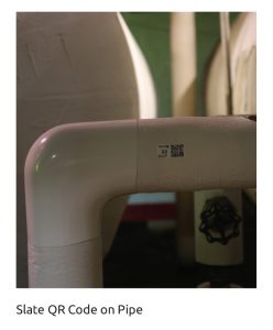
After several years, the system may have sustained damage—it’s common for valve insulation or parts of the straight pipe insulation to be removed or damaged during maintenance. The boiler room may get a little bit warmer every year and the gas bills slowly go up. The goal of creating an asset-tracking system would be to prevent these circumstances by mounting a scannable QR code sticker on the insulation that could be scanned after install and during routine inspection, bringing attention to potential issues.

Tracking Starts with an ID

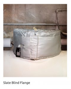
Although pipe insulation is not normally uniquely identified, most removable insulation jackets include a stamped stainless steel tag. The tag lists the insulated component type (gate valve, wye strainer, etc.). The tag may also contain pre-determined item numbers and location information. The amount of information is usually dictated by the size of the tag and the size of the font. The embryo of an idea formed. Our team looked at developing a “smart tag” that would be a unique identifier for pipe insulation.

The tag had to be industrial strength quality and be able to be scanned with an iOS app to enter and captured data. This tag is called a Slate and is powered by Slate Pages™.

The Process is Simple

Once the pipe insulation is installed, the installer scans the smart tag and enters in the following data:
• Insulation Asset Name
• Insulation Asset ID
• Location 1
• Location 2
• Location 3
• Install Date
• Btu loss per SF if uninsulated
• Btu loss per SF if insulated
• GPS coordinate
• Photo

The total scanning and data collection process takes less than 5 minutes.

Insulation Asset Name

The name usually contains the diameter of the pipe, the pipe thickness, and the linear feet of the pipe. If you were installing 50’ of 2”X1” hot water insulation in a single location, this would be one Insulation Asset. We found asset naming a little tricky in the beginning, but worked out a simple process. A group of pipe insulation gets its own asset name based on the following:

  • New Asset Name = Location, Temp, Pipe Size, Insulation Thickness

By way of example: If in a single location there was 30’ of 2×2” pipe on 220 degree steam, 100’ of 2×2” pipe on 220 degree steam, and 75’ of 2×1” pipe on 180 degree hot water, you would have 3 Insulation Assets to be tagged.

Insulation Asset ID

Asset ID is a unique numerical identifier to that asset name. It is like a serial number. Having this information allows us to quickly identify the quantity, installer, location, and date of install. We looked at numbering each job starting with 1, but found it just as easy to keep running numbers for all jobs.

Location 1

This is the building or complex name.

Location 2

This is the room number or room name.

Location 3

This is the location within a room.
Example: Cotter Hall, Boiler Room, Above Boiler 3

Install Date

This is the date the pipe insulation was installed.
BTU Loss per SF if Uninsulated
This is the amount of Btu loss per hour, per square foot, that a component is losing with no insulation.

BTU Loss per SF if Insulated

This is the amount of Btu loss per hour, per square foot, that a component is losing with the insulation. Insulation efficiency will still allow for minor heat loss.

GPS

The Slate App uses the location features built in the smartphone. When the Slate is scanned, the installer captures location to document the longitude and latitude position of the pipe insulation. This information can be displayed on the Slate portal in a map view and allows the user to access and edit the data by clicking on the map pin.

Photo

Once the installation is complete, the installer snaps a photo of the asset. This photo field is invaluable. It is used by project managers to verify quality and by building owners to track progress. The photos are also used by O&M inspection crews to verify the condition of the install since last inspection. Photos have been used on mechanical insulation projects since the digital camera was introduced—the issue is finding them when you need them. Slates eliminate that problem and link directly to the QR Code.

The Data Is Invaluable

After the insulation project is complete and the insulation assets have been scanned and uploaded, the information resides in 3 places: the Slate (QR Code), the installer’s phone, and the Web portal.

Maintenance Tracking

Each time the system is inspected or maintained, it can be tracked. The maintenance workers have the ability to scan the pipe insulation and view any of the data. In the past, mechanical insulation paperwork resided on the engineer’s computer. General maintenance workers had no idea what the insulation thickness was or the anticipated touch temperatures. With the tag, they can now scan the Slate and view the actual insulation savings as it relates to pre- and post-Btu savings. In our modern world, people expect to have having easy access to data—now that can extend to insulation.

Changing Energy Savings Perceptions

Energy savings is a bit of a mind game. Many workers often make sure to turn off a light or close a window when leaving a room or area. Subconsciously, they know that leaving the light on is wasting energy.

Insulation is a different story. When walking by an insulated pipe, it may be more typical to make note of the temperature, rather than the energy being lost. How many of us have walked by an uninsulated pipe and thought, “wow, that is hot.” Our brains are not yet programmed to think energy savings—we tend to focus on temperature or work area comfort or safety. This tracking system makes that information readily available to maintenance staff, helping them understand the amount of energy that is truly being wasted by uninsulated pipes, and retraining their concept of energy waste. Next, the process of finding time and funding to fix any issues begins.

That same worker will soon realize that there is more savings in one year if he or she insulated 100 linear feet of 2” bare medium-pressure steam piping than turning off all of the lights in the mechanical room for 10 years. When it comes to saving energy and money, mechanical insulation is a clear leader among energy-efficiency measures.
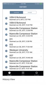
Phone

The app stores saved scans, which can be listed by Scanned or Viewed. Many of our installers frequently use the history function to call up an asset when they are off-site or if they are on a new project and have a similar situation and would like to compare to a historical proven solution.

Web Portal—Assets List View

The Web Portal truly is the secret sauce. While workers are installing pipe insulation and removable jackets, the project engineers, building owners, and construction managers are able to watch and view the project install from their desktop. The portal begins with the login. Every user creates a unique user name and password, and then every account is given an encrypted authorization code. This code is what the Insulation Assets are linked to. We link our assets by project instead of account. We could have a number of projects for a single account, but prefer to view them separately on a project-by-project view. Once signed into the portal, you can view your insulation Slates in a Slate view.

If the Slates are the building blocks to insulation asset management, the Web Portal is the foundation. The main screen shows the All Slate View List. This lists all Slates associated with the account.

You can add or remove columns when configuring the view. If the field exists on a Slate, you can add the column to your view. The column will sort, similar to Excel, when clicked on. Clients can also configure the portal to create specific views. Rules can be configured to only show specific assets. For example, you can display all of the insulation assets in a particular building, or all of the insulation assets of a particular kind (e.g., gate valves, 2” piping, steam traps, etc.).

View configuring is a great tool for project management. If a post-install photo is required for the project, the view can have the following rule added: Show me Slates where the Photo Field has a value. This will only display the Slates that have a photo. If a project manager is looking for a to do list, they can reverse the rule: Show me Slates where the Photo Field has NO value. This will then produce a list of insulation assets that do not have a photo. He or she can then send the list to the installer to complete.

When the preferred view is created, the manager can use the list to sort, export, or pick an individual insulation asset and display the details.

Web Portal—Map View

When a Slate is used, the end user has an option to add a Location Field. The Location Field simply uses the GPS location service on a smartphone. When this feature is used, the map view displays the assets onto a map view. The insulation assets are clustered in groups and allow zoom features on the map to narrow down to a specific building or mechanical room. Once in the room, you can click on a specific asset and expand the detail.

The default color for a pin is red. Similar to the list view, maps can be configured to create rules and change pin colors.

The Solution Is Ready

The mechanical insulation industry is about to join the asset management boom! Building owners can now have pipe insulation and removable jackets installed with a unique identifier. This identifier can then be used to link construction/install documents to the insulation. Once linked, the app can be used to facilitate yearly inspections to confirm the pipe insulation is still intact and doing its job.

The map view will allow the building owners to manage the operation and maintenance contracts by creating views, which only display the insulation that has current photos, verifying the pipe insulation has been inspected. Overall, this technology will facilitate better maintenance and ensure systems continue to perform at a high level.


Copyright Statement

This article was published in the September 2017 issue of Insulation Outlook magazine. Copyright © 2017 National Insulation Association. All rights reserved. The contents of this website and Insulation Outlook magazine may not be reproduced in any means, in whole or in part, without the prior written permission of the publisher and NIA. Any unauthorized duplication is strictly prohibited and would violate NIA’s copyright and may violate other copyright agreements that NIA has with authors and partners. Contact publisher@insulation.org to reprint or reproduce this content.

One of the most significant concerns for any plant engineer is how to save energy and operating costs. One way is by utilizing the appropriate pipe support components within the plant’s piping system. Choosing the wrong type of pipe supports can lead to extremely high costs, heat loss, corrosion under insulation (CUI), and a host of other issues. These problems can be resolved by choosing an appropriate insulated pipe support for your system. One option is pre-insulated pipe supports.

Pre-insulated pipe supports are used in a variety of applications, including above-ground piping and piping in buildings, tunnels, and trenches. They can be designed for high-temperature, cold-temperature, and even dual-temperature applications. High temperature pre-insulated supports utilize structural inserts within the support for load carrying and clamping capabilities. Low-temperature supports use various materials and densities to carry the load of the pipe. Composites of several different insulations such as aerogel blanket, calcium silicate, cellular glass, and closed-cell foam insulation may be utilized for special applications at a wide range of service temperatures.

Pipe supports that clamp or weld directly to the pipe have documented inefficiencies. As an example, thermal analysis performed by infrared photography on a high-temperature pipeline (see Figure 1) indicated that significant amounts of heat from this pipeline were being transferred from the pipe to the uninsulated steel pipe support welded to the bottom of the pipe. This caused a great deal of heat to escape into the pipe rack and the environment, affecting the surrounding area as well as inefficiently releasing BTUs of energy at the pipe support locations, thus negatively affecting the performance and efficiency of the pipeline.

Pre-insulated pipe supports help isolate the pipe from the outside structure for maximum efficiency. They offer an immediate thermal break and eliminate “radiator fin” heat loss or gain, depending on the service temperature of the system. Pre-insulated supports function to keep heat in or out of the pipe as desired depending on the service temperature of the pipe.

Another approach to pre-insulating a pipeline is by “modularizing” the piping system using sections of pipe that can be pre-assembled with insulated supports, insulation, and cladding at an offsite location. This system approach minimizes laydown space issues and significantly reduces labor time, resulting in cost savings for the project. These “piping modules” can be conveniently installed on the pipeline with all of the piping components already in place. Additional benefits include an improved project schedule, safe working conditions at waist-high levels, decreases in scaffolding, and overall construction cost savings.


Pre-insulated pipe supports can offer easier installation than non-insulated supports in some cases. Weld-on supports require expensive labor rates for time-consuming welds, along with additional inspection time by quality control. It can be laborious to trim the insulation and jacket around the steel ribs of the support. Meanwhile, pre-insulated pipe supports bolt on to the pipe for fast and secure installation. After bolting, the installation is complete as the insulation and cladding are part of the entire installed unit. In some cases, the reduction in labor cost more than makes up for the higher material cost of a pre-insulated pipe support.

CUI and pipeline condensation are issues that can occur on a pipeline. Pre-insulated pipe supports totally isolate the pipe from the outside structure and can include a sealed vapor barrier and line stop system to eliminate these types of issues at the pipe support locations.

There are many factors when choosing between uninsulated weld-on and clamp-on supports or pre-insulated pipe supports. Supports must be properly insulated to save on operating costs, time, pipeline efficiency performance, and to protect against serious damage to the pipeline throughout the lifetime of the plant.


Copyright Statement

This article was published in the August 2017 issue of Insulation Outlook magazine. Copyright © 2017 National Insulation Association. All rights reserved. The contents of this website and Insulation Outlook magazine may not be reproduced in any means, in whole or in part, without the prior written permission of the publisher and NIA. Any unauthorized duplication is strictly prohibited and would violate NIA’s copyright and may violate other copyright agreements that NIA has with authors and partners. Contact publisher@insulation.org to reprint or reproduce this content.

With summer well underway, don’t be caught ill-prepared for a heat-stress incident and a subsequent visit by the Occupational Safety and Health Administration (OSHA)—establish your heat stress program today. Simply telling your employees that it is a hot day and they should take breaks when needed and to drink as much water as necessary will not meet OSHA’s expectations and could very easily result in a citation.

The risk of heat stress depends upon many factors related to the individual employee, and this makes the challenge of making a safe workplace for all employees even more challenging. Risk factors include the employee’s physical condition, the temperature and humidity, clothing worn, the pace of work and how strenuous it may be, exposure
to sun, and environmental conditions such as air movement.

OSHA expects more from employers than merely offering water, rest, and shade. Additional steps to address heat in the workplace need to be taken. OSHA also insists upon:

  1. Implementing an “acclimatization program” for new employees and those who are returning from extended time away, such as vacations or leaves of absence;
  2. Implementing a work/rest schedule; and
  3. Providing a climate-controlled area for cool down.

For those employers utilizing temporary employees, there is a greater risk of heat-related illnesses, and OSHA urges greater care in adopting an acclimatization program for them.

Your heat stress program can have many components, including:

  • Training

    • Hazards of stress;
    • Responsibility to avoid heat stress;
    • Recognition of danger signs/symptoms (because employees may not recognize their own);
    • First aid procedure; and
    • Effects of certain medications in hot environments.
  • Personal Protective Clothing/Equipment

    • Light summer clothing, which allows free movement and sweat evaporation;
    • Loosely worn reflective clothing to deflect heat; and
    • Cooling vests and wetted clothing for special circumstances.
  • Administrative/Engineering Controls

    • Assess the demands of all jobs and have monitoring and control strategies in place for hot days and hot workplaces;
    • Schedule hot jobs for cooler parts of the day;
    • Reduce physical demands;
    • Permit employees to take intermittent rest breaks with water breaks and use relief workers;
    • Have air conditioning and shaded areas available for breaks/rest periods with ice available;
    • Increase air movement; and
    • Exhaust hot air and steam.
  • Health Screening/Acclimatization

    • Let employees get used to hot working conditions by using a staggered approach over several days, such as beginning work with 50% of the normal workload and time spent in the hot environment and then generally increase it over 5 days.
    • Make employees aware that alcohol abuse and certain medications, such as diuretics, anti-hypertensives (blood pressure), and anticholinergics (pulmonary disease—COPD), can exacerbate problems.

OSHA is also inclined to cite an employer if prompt remedial action is not taken when an employee falls victim to heat stress. Establish specific procedures for heat-related emergencies and provisions for first aid when symptoms appear. Remember, employees may resist first aid because of the confusion caused by their heat stress. Training on the signs and symptoms is also encouraged.


Copyright Statement

This article was published in the August 2017 issue of Insulation Outlook magazine. Copyright © 2017 National Insulation Association. All rights reserved. The contents of this website and Insulation Outlook magazine may not be reproduced in any means, in whole or in part, without the prior written permission of the publisher and NIA. Any unauthorized duplication is strictly prohibited and would violate NIA’s copyright and may violate other copyright agreements that NIA has with authors and partners. Contact publisher@insulation.org to reprint or reproduce this content.

When people ask me what I do for a living my response is, “Go inside any commercial building or garage and look up.” It may not be glamorous, but it is extremely important. The primary reason for insulated pipe supports is to support the weight of the pipe. The secondary reason is to provide continuous insulation throughout the system. In addition, many pipes expand and contract as the temperature becomes hotter or colder. Without an insulated pipe support, this expansion and contraction may stress the pipe and may cause damage. Insulating a complete system is key to maintaining insulation’s benefits. The insulated pipe support is essential to the proper functioning of the entire hanger assembly.

The most important thing that we have learned from listening to our customers for more than 26 years is that when it comes to insulated pipe supports, a seamless and integrated system design is vital to the success of the installation, function, and long-term viability of the product. This creates a functional support and also adds aesthetic value to the overall installation.

There are 3 distinct market segments within the contracting community for utilizing insulated pipe supports. They each have unique requirements and needs specific to the installation.

Mechanical

The mechanical trade installs the hanger assembly. This includes steel, cast iron, and stainless steel, copper, and plastic pipes.

Plumbing

The plumbing trade installs 3 types of pipe, with supports required for all 3. This includes copper, cast iron, and thermoplastic.

Insulation

Per ASTM C-585, the dimensional standard for pre-formed thermal insulation for pipes and tubing, insulated pipe supports must match the outside diameter of the pipe and installation. This is important because each support needs to fit the pipe without being too loose or tight. Without a proper fit, the pipe has unnecessary stress that could cause it to crack or break.

In addition to controlling temperature and saving energy, 2 of the great advantages of insulated pipe supports in this industry are ease and time savings. Insulated pipe supports installed on a clevis hanger are incredibly simple to install. The contractor doesn’t have to work directly with the pipe hanger and the installation process only requires making a butt joint between the pipe insulation system and the insulated support.

Important Industry Considerations

When utilizing insulated pipe supports, there are many important considerations to weigh.

Flame/Smoke Rating per ASTM E84—This test measures both a flame spread index and a smoke developed index of the flat material being tested. Various factors, including location within a building, determine the flame/smoke indices required. In plenums, pipe insulation must meet a flame/smoke index no greater than 25/50.

Vapor Retarders—Vapor retarders greatly reduce the flow of moisture from the ambient environment into the insulation system. This is important to prevent mold and pipe corrosion, to reduce the likelihood of surface condensation on the insulation system, and to improve the longevity of the insulation system. The standard is a maximum of a 0.02 perm rating for the vapor retarder.

Insulation within the Support Must Carry the Weight of the Pipe—Many factors must be considered related to supporting the weight of the pipe. These include the span between supports, shield length, safety factors, pipe size and schedule, pipe contents, and more. Remember that you are not just supporting the pipes, but the fluid as well. Taking shortcuts to save time or money by placing supports further apart without using commensurately higher strength insulation at the supports can cause deterioration and breakage of the insulation at the support locations.

Seismic Conditions—Seismic conditions must be addressed. You must make sure the hanger assembly has the ability to maintain its integrity in an earthquake.

Critical Manufacturer Requirements

Not all insulated pipe supports are equal. Here are some important facts to consider.

Fire Rating—Make sure the product you are using is tested by the manufacturer per ASTM E84. The product must be tested for fire rating.

We often run across products that are foam based or use wood blocks. Keep in mind that foam-based products have widely varying flame/smoke ratings and wood blocks are not a fire-rated product. Even worse, wood blocks provide a food source for mold.

Vapor Retarder—Another critical consideration is the insulation vapor retarder. Insulation vapor retarders are generally stressed on systems that run below ambient temperature. A sealed vapor retarder is the first line of defense against water vapor intrusion and corrosion under the insulation. These would be most prevalent on systems operating between 100˚F and 300˚F. The best solution is a full sealed vapor retarder through the hanger. It should extend past the protection shield so that it seals the entire insulation system.

Different types of effective vapor barriers include:

  • Metalized polyester all service jacket (ASJ);
  • Zero-perm products; and
  • Polyvinylidene chloride (PVDC).

You will sometimes see PVC jacketing and galvanized metal offered as a vapor barrier. Keep in mind that these products are not vapor retarders and should not be used for this purpose.

Common Products Used in the Pipe Support Industry

Calcium Silicate

One of the advantages of using calcium silicate is that this product is dense and provides a great deal of structural support with a compressive strength of 100 PSI. The dense nature of this product means that the pipe support doesn’t have to be as long because it provides structural strength. We recommend the use of this product in the majority of our hot applications and cold applications with a vapor barrier.

Polyisocyanurate

Polyisocyanurate is a good option for cold and cryogenic applications. This product is closed cell, which is beneficial because it limits the moisture intrusion. Some grades of PIR have 25/50 flame/smoke ratings and most grades meet a flame/smoke rating of Class A/Class 1. Also keep in mind that in an installation, you must match the density of the foam used in the supports to the forces exerted at these locations. Larger spans between supports usually will require greater compressive strength from the insulation so this must be considered. The larger the pipe span, the more you must increase the density to support the weight of the pipe. Density ranges from 2 ½ to over 30 pounds.

Phenolic Foam

This product is a good option for cold applications such as refrigeration and chilled water. Up to 3 inches thick phenolic, which is the most that would be needed in these applications, has a flame/smoke rating of ≤25/50, so it can be used as pipe insulation in commercial building areas.

Cellular Glass

While I do not often use it, cellular glass is a closed-cell non-combustible foam of glass. It is used in both above- and below-ambient systems as insulated pipe supports for small- to medium-diameter piping.

Pipe Support Guidance

There are multiple governing bodies within this industry that we rely on for building or pipe support standards.

ASHRAE—American Society of Heating, Refrigeration, and Air Conditioning Engineers

ASHRAE publishes standards and guidelines that relate to HVAC systems and issues. These standards are part of many building codes.

ANSI—American National Standards Institute

ANSI is a nonprofit organization that oversees many of the standards that we use. ANSI does not develop standards but works with those developing standards to ensure the procedures used are solid. ANSI accreditation indicates that the procedures used meet requirements for openness, balance, consensus, and due process.

ASTM—American Society for Testing and Materials

ASTM develops over 12,000 voluntary consensus standards, many of which apply to the pipe-support industry. These are referenced frequently and many become mandatory by corporation and government contracts.

AWS—American Welding Society

The American Welding Society maintains code and certification procedures, which help to provide industry standards for the welding and joining of metal, plastics, and other materials.

MSS—Manufacturers Standardization Society

The MSS of the valve and fittings industry references all of the pipe support standards when outlining procedures for manufacturing components and systems for the field.

These standards have been a driving force in our industry for nearly 60 years since they were first set in 1958. Here are some key components of the standards that apply to the insulated pipe support industry.

  • A Type 40 shield is defined by the length and gauge on the outside of the insulation.
  • The minimum requirement is 18 gauge and 12” long.

In 1966, the MSS standards were updated to allow for an alternative type 40 shield. They require:

  • High compressive strength insert (6” and larger seems to be the standard in most applications);
  • Vapor barrier; and
  • Appropriate shield.

Industrial Market

Insulated pipe supports in the industrial market are unique and special in many ways. The majority of applications are highly customized and engineered. We rarely see “off the shelf” products for this market. Some of the considerations for the industrial market include:

  • Large pipes. Some pipe hangers are so large you can walk through them!
  • Higher loads. They need to be created to withstand much higher loads than any off-the-shelf product.
  • More movement. Industrial applications tend to see more movement in the pipe due to large volume and greater differences in temperatures.
  • Low Temperatures. In some cold applications, products need to be designed to withstand temperatures as low as -320°F and sometimes even colder.
  • High Temperatures. Products need to be designed to withstand temperatures as high as 1500°F in some cases.

Higher Temperatures in the Industrial Market

In the higher-temperature industrial market, denser materials are made from high temperature, calcium silicate (Type II, Grade 5 and 6) board material. Boards start at a compressive strength of 450 PSI and go as high as 3050 PSI. Pipe loads determine the length of insulated pipe support. The larger the pipe, the longer the support must be in order to properly hold the weight. The MSS sets the standards for minimal allowable loads between hangers.

Cryogenic Applications in the Industrial Market

In applications that produce incredibly low temperatures, another unique set of requirements is presented. The density of poured urethane foam starts at 2 pounds per cubic foot (PCF) and goes to 30 PCF. Multilayer and low permeance vapor retarders are required in order to keep ice from forming and to minimize moisture intrusion into the insulation system.

For hot and cold industrial applications, insulation thickness varies widely depending on many factors. It can be as little as ½ inch to nearly unlimited thickness depending on the project.

Advantages of Insulated Pipe Supports

For a contractor, one of the biggest advantages of utilizing an insulated pipe support is cost savings. Whether the application is for mechanical or plumbing, the presence of the insulated pipe supports reduces the amount of labor required by the contractor. Depending on the size of the project, this can result in large cost savings or the ability to lower your bid and win projects.

As a building or facility owner, insulated pipe supports help to conserve energy. They will continuously help to reduce heating and cooling costs in the buildings where they are installed. A properly insulated system means equipment doesn’t have to work as hard, therefore reducing maintenance costs. This also helps avoid down time and extends the life of the equipment and the insulation system.

Partner with Experts

For a successful outcome, make sure to partner with companies that have deep expertise in this industry. Know the markets you serve and make sure to be knowledgeable about the relevant standards that apply.


Copyright Statement

This article was published in the August 2017 issue of Insulation Outlook magazine. Copyright © 2017 National Insulation Association. All rights reserved. The contents of this website and Insulation Outlook magazine may not be reproduced in any means, in whole or in part, without the prior written permission of the publisher and NIA. Any unauthorized duplication is strictly prohibited and would violate NIA’s copyright and may violate other copyright agreements that NIA has with authors and partners. Contact publisher@insulation.org to reprint or reproduce this content.


Design engineers have utilized various methods to ensure the integrity of pipe insulation systems at pipe-support locations. The success of these methods depends heavily on the engineer’s foresight and understanding of the variables acting on the support location over the life of the system. In addition to the system requirements, optimal design and specification will factor in the following risks:

Risk of Poor Installation: Did the installer really use the rigid support that was specified at every hanger location? Were there wood blocks and were they properly aligned and centered over the hanger? How can this be assured upon inspection?
Inadequate Maintenance: What happens if the vapor retarder is damaged?
Dynamic Nature of Mechanical Systems: There is a degree of uncertainty regarding the extent to which linear expansion/contraction, water hammer, and other system movement and abuse will occur over the life of the system.

The selection of insulation material, vapor retarders, and adequate support are especially crucial for cold piping. Poorly supported systems are highly susceptible to damaged vapor retarders. When water vapor reaches the pipe surface and condensation occurs, fibrous or granular insulation and pipe meet their shared nemesis head on. The water-logged insulation system joins forces with the oxygen in the air to create a perfect recipe for corrosion under insulation (CUI) and mold formation.

For these reasons, systems operating at below ambient temperatures can be insulated with a closed-cell insulation material as a secondary defense to the threat of a penetrated or damaged vapor retarder. Additionally, a low permeance vapor retarder meeting the industry standard of ≤0.02 perms provides added protection to any existing vapor retarder that is commonly pre-applied to fiber glass pipe covering.

The increased risk of mold and CUI in cold systems adds to the significance of detailed pipe support specifications. The strongest specifications usually involve different pipe support materials for cold and hot systems as well as special considerations for pipe resting on a flat surface as opposed to a clevis hanger. This article will provide insight for engineers to consider as they evaluate their options for supporting insulated piping.

Wood Blocks and Saddles

The most commonly specified and traditional means of supporting and protecting insulated piping in many applications is with wood blocks and insulation protection shields (commonly referred to as saddles by insulators). This method offers the lowest material cost to accomplish the goal. However, it is often incorrectly specified and is not recommended by ASHRAE or the National Commercial & Industrial Insulation Standards manual (also known as the MICA Manual). There are some key reasons to take caution before moving forward with wood blocks and saddles:

  1. Wood burns, and it should not be specified when the design is subject to compliance with the latest update to the International Mechanical Code (2015) Section 602.2.1. It states that “materials within plenums shall be noncombustible or shall be listed and labeled as having a flame spread index of not more than 25 and a smoke-developed index of not more than 50 when tested in accordance with ASTM E84 or UL 723.”
  2. Unless inspection occurs during the installation, verification of correct sizes and quantities of wood blocks cannot be guaranteed upon visual inspection.
  3. Wood is naturally hygroscopic, which makes it a poor choice for systems operating at below-ambient temperatures. If and when the vapor protection is compromised, condensation will quickly be absorbed by the wood. Wood blocks, with their poor thermal conductivity, may cause condensation at their locations. At this point, the risk of mold formation and CUI is much greater.
  4. When wood blocks are used in conjunction with a flat resting surface (pipe rack, trapeze, strut, etc.), it is important to account for the increased point load compared to a clevis hanger, where weight can be better distributed across multiple blocks. The only support that can be considered load-bearing is the bottommost wood block when pipe is rested on a flat surface.


Small diameter piping may not be affected, but it is common to see large piping suspended by strut with bowed saddles. Performing point load calculations will help determine if an additional steel plate is necessary to add structural stability and help disburse the load between the galvanized saddle and the flat support surface.

High-Density Fiber Glass Blocks and Saddles

The fact that wood is combustible has driven many engineers to eliminate wood blocks as an option entirely. The next most cost-efficient support mechanism is high-density fiber glass blocks. Depending on the supplier, fiber glass blocks offer a K-factor of approximately .30, various compressive resistances, and can perform well at higher operating temperatures.

Most importantly, fiber glass blocks can be used in plenum spaces with a flame-spread and smoke-developed rating of 10/10 per ASTM E84. However, some of the downfalls associated with wood blocks still exist and should be noted:

  1. Unless inspection occurs during the installation, verification of correct sizes and quantities of fiber glass blocks cannot be guaranteed by visual inspection.
  2. Though the binding agent offers some minimal resistance to liquid water ingress, fibrous insulation material still has open air space between fibers and offers little resistance to water vapor. Water and moisture retention can occur, resulting in loss of insulating ability, mold, or CUI.
  3. Leading manufacturers have charts similar to the previous example for wood blocks that indicate proper lengths and quantity requirements per pipe size. Visual verification of proper install remains a concern for inspectors.
  4. Inspection must occur during installation. It is impossible to tell how many fiber glass blocks were installed at any given support location upon completion. Lack of visual verification also prohibits verification that the supports are composed of high density fiber glass as opposed to wood.
  5. The installation of block-style supports requires the installer to carefully cut and remove fiber glass material from the inside of a clam-shell section of fiber glass pipe cover. Most often, the fiber glass pipe covering is pre-jacketed with an all service jacket (ASJ) that serves as the vapor retarder. It takes precision with a filet knife in order to preserve the integrity of the jacket without penetration. Even the most skilled insulator is bound to cut through the ASJ when this process is repeated for hundreds of support locations on a large project.

Rigid Insulation Insert and Saddles

As previously stated, closed-cell insulation is often preferred for below-ambient piping. Three prime candidates to meet this need are cellular glass, phenolic foam, and polyisocyanurate insulation—all of which have the added benefit of a rigid structure. At high enough densities, these 3 materials will provide sufficient compressive strength to serve as a support mechanism. When engineers use the term “rigid insulation insert” in specifications, one hopes performance characteristics of the insulation, jacket, and saddle will be laid out with the option for the field assembly of the components.

While not rigid, some form of elastomeric insulation is another common closed-cell solution. The “insert” material of choice might be one of the 3 aforementioned rigid insulations. Additionally, some elastomeric insulation manufacturers have developed proprietary insulated pipe support systems.

Most hot water piping systems also operate at temperatures suitable for cellular glass, phenolic foam, or polyisocyanurate insulations. However, calcium silicate is most common due to its superior compressive strength.

The practice of specifying a rigid insulation material to support piping is becoming more popular across the country. It translates to a higher level of confidence in the integrity of the insulation system at pipe support locations. The consistent compressive strength and load distribution of such materials reduces the risks associated with poorly installed blocks.

Rigid insulation inserts can be fabricated in the field or by a dedicated insulation fabricator as determined by the specification or the installing contractor. Material cost compared to blocks will be higher either way, but the growth in demand for such products suggests that the added value outweighs the higher material cost. Specifications for rigid insulation inserts and saddles must include more detail than block-style specifications in order to truly realize the added value. Here are some tips to keep in mind:

  1. Be specific about length of insert material, type of vapor retarder, length and gauge of saddle per size, allowance for circumferential tape enclosure, etc. Otherwise, it will result in multiple requests for information.
  2. Clearly define that the insulation inserts (with jacket and saddle) should be installed when setting the pipe elevation. If this is not defined, there is a risk that the insulation contractor will unintentionally modify the elevations when lowering and raising clevis hangers during support installation. Depending on the circumstances, the efficiency of the mechanical system can be greatly lessened.
  3. Ensure that the insulation material is suitable for the demands of the system and code requirements. Only closed-cell insulation should be allowed in below-ambient conditions. Also evaluate the flame and smoke ratings, which will differ for some materials depending on the insulation thickness.
  4. Load distribution calculations are the only tried and true way to determine if an additional plate is required below the saddle.
  5. Site visits are necessary to verify that the specified materials are being installed. Visual inspection of supports, especially after the insulation system installation has been completed, does not confirm compliance with specification.

Insulated Pipe Support Systems

This category encompasses a system approach to supporting insulated piping. In other words, each system ships as a finished product that includes rigid insulation material, vapor retarder, and saddle. Insulated pipe support systems are unique to the application for which they are intended. Each is defined by a detailed specification in the form of
a technical data sheet. Usually, there is a brand name associated with the line of insulated pipe support systems.

The systems approach boasts all of the benefits of the rigid insulation insert and saddle combination with added benefits.

  1. Specification compliance can be visually verified upon inspection by way of the manufacturer’s sticker on the bottom of the support.
  2. Specifying engineers can confidently select and rely on insulated support systems based on manufacturer recommendations. Manufacturers will naturally stand behind their products and many will provide installer training if desired.
  3. Choosing insulated pipe support systems over any field-fabricated support method shifts the variable cost of labor to the fixed cost of materials, thus reducing the overall risk exposure. Decreased labor risk leads to more surety in the project timeline, less chance of job site injuries, and less chance for installer error.

Dedicating additional time and effort to pipe support specifications is a practice that will vastly improve the performance of an overall pipe insulation system. Like anything else, the system is only as good as its weakest link. Even small areas of damaged insulation can translate to substantial additional energy costs over time. Water-saturated insulation can be worse than having no insulation at all, so it is important to choose materials carefully and install them properly.


Copyright Statement

This article was published in the August 2017 issue of Insulation Outlook magazine. Copyright © 2017 National Insulation Association. All rights reserved. The contents of this website and Insulation Outlook magazine may not be reproduced in any means, in whole or in part, without the prior written permission of the publisher and NIA. Any unauthorized duplication is strictly prohibited and would violate NIA’s copyright and may violate other copyright agreements that NIA has with authors and partners. Contact publisher@insulation.org to reprint or reproduce this content.