Category Archives: Global

President
Barack Obama’s landmark speech on June 25 outlining executive actions to combat
and prepare for climate change backed the growth of natural gas and renewable
power in lieu of carbon-heavy coal power, but he mentioned nuclear power only
once—and only in the context of energy security.

The
President’s speech closely mirrored the White House’s June 25 release of a 21-page
blueprint, a document the President called a Climate Action Plan (CAP), which
charts the executive branch’s efforts to achieve its 2009 pledge to reduce U.S.
greenhouse gases (GHGs) by 17% from 2005 levels by 2020.

Curbing Carbon Through GHG Rules for Power
Plants

The plan “begins” with
slashing carbon pollution by “changing the way we use energy,” Obama said. That
would require “using less dirty energy, using more clean energy, wasting less
energy throughout our economy.” But this does not mean “we’re going to suddenly
stop producing fossil fuels,” he said. “Our economy wouldn’t run very well if
it did. And transitioning to a clean energy economy takes time.”

However,
40% of U.S. carbon pollution is emitted by power plants, and no federal limits
to the amount of carbon pollution exist, the President noted. “We limit the
amount of toxic chemicals like mercury and sulfur and arsenic in our air or our
water, but power plants can still dump unlimited amounts of carbon pollution
into the air for free. That’s not right, that’s not safe, and it needs to stop.”

As a
first measure to combat climate change, the President therefore directed the
Environmental Protection Agency (EPA) to complete issuance of its final New
Source Performance Standards for GHG emissions, which it has postponed, missing
its April 13 deadline because it was reportedly still reviewing more than 2
million comments on its proposal. That rule establishes carbon dioxide
standards for certain new and reconstructed coal and gas generators, limiting
emissions to 1,000 pounds/MWh. President Obama called on the EPA, however, to
develop standards for that rule affecting new power plants—and another for
existing power plants—”in an open and transparent way, to provide flexibility
to different states with different needs, and build on the leadership that many
states, and cities, and companies have already shown.”

The
Supreme Court has ruled GHGs are pollutants covered by the Clean Air Act, and
the EPA had in 2009 determined GHGs are a threat to public health and welfare
and therefore subject to regulation, the President noted. Meanwhile, a “dozen
states” have already implemented their own market-based programs to reduce
carbon pollution, 25 have set energy efficiency targets, and 35 have set
renewable energy targets. “It’s just time for Washington to catch up with the
rest of the country,” he said.

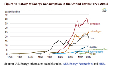
Heavy on Natural Gas and Renewables

Though
the President mentioned his much-reiterated “all-of-the-above” energy strategy,
he prominently lauded increased U.S. production of what he called
“cleaner-burning” natural gas. “We should strengthen our position as the top
natural gas producer because, in the medium term at least, it not only can
provide safe, cheap power, but it can also help reduce our carbon emissions,”
he said. Natural gas is creating jobs, lowering power bills, and “it’s the
transition fuel that can power our economy with less carbon pollution even as
our businesses work to develop and then deploy more of the technology required
for the even cleaner energy economy of the future.”

Obama
also called for doubling current levels of renewables by 2020. Notably, he
called on the federal government to source 20% of its power from renewables by
2020 and urged the Department of the Interior to approve over the next 7 years
an additional 10 GW (beyond the 10 GW already permitted) of private renewable
energy capacity on public lands. He also called on the Department of Defense to
install 3 GW of renewable power on its bases.

A Nuclear-Shy Plan

In the President’s
speech, as in the White House’s CAP blueprint, mention of nuclear power’s
future role as a clean energy source to combat climate change was largely
absent.

Industry
experts had expected the White House’s climate change strategy to be founded on
recommendations by the President’s Council of Advisors on Science and
Technology (PCAST) released this March. The council called for continued
efforts to “decarbonize the economy,” with an emphasis on the power sector, and
removal of regulatory obstacles (such as lower financing costs) to “level the
playing field” for renewables, carbon capture and storage, nuclear power, and
energy-efficiency technologies. PCAST had specifically lauded nuclear’s role in
efforts to curb climate change, saying: “Achieving low-carbon goals without a
substantial contribution from nuclear power is possible, but extremely
difficult.”

In
his recent speech, the President noted that nuclear was a key of the U.S.
strategy for a secure energy future—and that the country’s first new nuclear
plants had broken ground this year for the first time in 3 decades. But while
future efforts to curb climate change would require the use of “more clean
energy,” he set the focus on doubling wind and solar energy from current levels
by 2020.

Marvin
Fertel, President and CEO of industry lobby group the Nuclear Energy Institute
(NEI) told POWERnews on Tuesday that the administration was well aware that the
nation could not reach its energy and climate goals without nuclear power.
“President Obama recognized this during the presidential campaign when he said,
?It is unlikely we can meet our aggressive climate goals if we eliminate
nuclear power as an option.’ Likewise, Energy Secretary Ernest Moniz supports
the expansion of nuclear energy to meet national energy and environmental
imperatives,” Fertel said. “We look forward to working with the administration
to help achieve these extremely important goals.”

International Efforts

Notable
global measures called for by the President in his speech included an outright
termination of U.S. public financing for new foreign coal plants without carbon
capture.

The
pledge could bar the U.S.-backed Export-Import (Ex-Im) Bank from financing a
number of major fossil fuel power plants. According to environmental group
Pacific Environment, the Ex-Im Bank has supported a number of massive projects,
including financing for the 4-GW Sasan coal project in India and the
4.8-GW Kusile coal
project in South Africa. The lender’s financing for fossil fuel projects
(including oil-field exploration, pipelines, refineries, and gas power plants)
reached $9.6 billion in the 2012 fiscal year.

Obama
said he would direct his administration to launch negotiations toward global
free trade in environmental goods and services, including clean energy
technology, to help more countries skip past the dirty phase of development.
“They don’t have to repeat all the same mistakes that we made.”

Another
significant action pledged by the President was to “redouble . . . efforts” to
engage international partners in reaching a new global agreement to reduce
carbon pollution through concrete actions. “What we need is an agreement that’s
ambitious—because that’s what the scale of the challenge demands. We need an
inclusive agreement—because every country has to play its part. And we need an
agreement that’s flexible—because different nations have different needs,” he
said.

A Reason to Act

As he had in his February
2013 State of the Union address, President Obama urged Congress to come up with
a bipartisan, “market-based” solution to climate change. “But this is a challenge
that does not pause for partisan gridlock. It demands our attention now,” he
said.

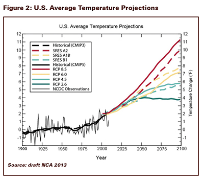
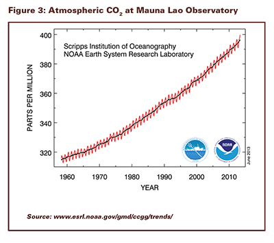
The President briefly summarized the history of climate
change science. He pointed out that scientists have known since the 1800s that
GHGs like CO2 trap heat and “that burning fossil fuels release those
gases into the air.” But he noted that only in the 1950s did concerns emerge
(from the National Weather Service) that rising GHG levels might disrupt the
“fragile balance.” That data “accumulated and reviewed over decades, tells us
that our planet is changing in ways that will have profound impacts on all of
humankind,” he said.

No
single weather event could be caused solely by climate change, the President
said, but there is consensus that the world is warmer than it used to be, and
“all weather events are affected by a warming planet.” It is fact that the 12
warmest years in recorded history have all come in the past 15 years, and that
last year, temperatures in some areas of the ocean reached record highs, and
ice in the Arctic shrank to its smallest size on record—faster than most models
had predicted it would. It is also fact that sea level in New York Harbor is a
foot higher than a century ago, he said. “That didn’t cause Hurricane Sandy,
but it certainly contributed to the destruction that left large parts of our
mightiest city dark and underwater.”

Climate change could have a measurable economic impact,
he suggested: “Farmers see crops wilted one year, washed away the next; and the
higher food prices get passed on to you, the American consumer. Americans
across the country are already paying the price of inaction in insurance
premiums, state and local taxes, and the costs of rebuilding and disaster
relief.”

The
question is not “whether we need to act,” the President said, pointing to an
“overwhelming judgment of science—of chemistry and physics and millions of
measurements,” it is “whether we will have the courage to act before it is too
late.

Are you trying to find the
right type of insulation material for your job but don’t want to search website
after website? Do you want to quickly and easily compare insulation products?
Are you looking for a source to answer all your questions? You’ve found it: The
MIDG and MTL Product Catalog!

NIA has a
tremendous resource available for those who are looking for information on
design specifications and insulation materials. The online MTL Product Catalog
is the only online library of technical product literature for the insulation
industry. It is perfect for finding materials for your specifications and
finding information on newly developed products. Categories of insulation
materials are listed on the main page, as well as participating companies, so
you can easily search and find the manufacturers and distributors and their
products with one click. From your search results, choose the product
literature to find out more about the specific product and its physical
properties. Companies can list their spec sheets, their Material Safety Data
Sheets (MSDS), installation guides, and marketing brochures. Businesses can
also update their data around the clock, giving you access to the most updated
information and insulation products. The MTL Product Catalog also contains
contact information for distributors and manufacturers and links to
participating companies’ websites so you can contact them for more information
or to purchase products. It is an invaluable asset. Why waste time searching
for individual manufacturers and scanning their websites for information when
you can find it all on one website?

Not even sure what type of
insulation material you might need? Let the Mechanical Insulation Design Guide
(MIDG) walk you through all the design considerations and help you figure it
out.

The MTL Product Catalog is also linked with the
Mechanical Insulation Design Guide (MIDG). Drawing on information from industry
experts and trusted resources, the MIDG website provides a easy to use
step-by-step guide on how to design an insulation system and choose the
insulation materials for your next project. It takes you through design
considerations such as abuse resistance, condensation control, energy
conservation, economics, fire safety, freeze protection, maintenance, noise
control, personnel protection, and process control. The MIDG provides simple
calculators and is a comprehensive source of information on the performance,
use, testing, and standardization of thermal insulation in buildings and
industrial facilities. Users are able to choose the insulation material type
that is best for their project and find a vendor on the MTL Product Catalog.
Using
the MTL Product Catalog in combination with the MIDG can solve all your design
and specification problems and provide a wealth of useful information on
products, businesses, and project planning.

The MTL Product Catalog is located on NIA’s
website at www.insulation.org/mtl, and the MIDG can be found at www.wbdg.org/midg.

New for 2013!

NIA is working on adding new resources to the site
to make the MTL Product Catalog a completely comprehensive guide for anyone
looking for information on insulation products for a project, design, or
specification. It now includes links to the insulation science glossary; product data sheets; specifications; complete lists of
NIA manufacturers, distributors, and members; product
and insulation
videos; and more. There is no other site that offers this depth of information
combined with high levels of insulation expertise.

Looking for a way to get end users to find your
product? Do you want to increase traffic to your website? NIA has an excellent
opportunity for businesses looking to increase customer exposure: the
Manufacturers Technical Literature (MTL) Product Catalog. Thousands turn to
NIA’s website, www.insulation.org,, for insulation resources; we created
the MTL Product Catalog on our site as a way to help companies bring their
product information directly to those who need it. The MTL Product Catalog is
easily searchable, user-friendly, and you can update your content 24 hours a
day at your convenience. You can also upload unlimited PDFs, so you have
complete control of the content your company offers. Additionally, the MTL
Product Catalog is linked to the Mechanical Insulation Design Guide (MIDG) as
part of the National Institute of Building Sciences’ Whole Building Design
Guide, which explains how to design an insulation system. The MIDG walks users
through the design considerations and provides information on the performance,
use, testing, and standardization of thermal insulation for mechanical systems
in building and industrial facilities. Users are able to choose the
insulation material type that is best for their project and find a vendor on
the MTL Product Catalog. Are you listed or is your competitor?

This guide is accessed by
approximately 10,500 users per month. Approximately 75% of these users access
information specifically on design, specifications, and insulation materials
and systems, representing a significant potential client base that has direct
access to the MTL Product Catalog. This partnership represents the only online
resource that takes users through a step-by-step process to choose the best
insulation product for their project. Combining the authority and knowledge of
the MIDG with the user-friendly MTL Product Catalog allows customers to
purchase insulation products with confidence.

The MTL Product Catalog
makes it simple for end-users to find the right product, read detailed product
descriptions, and contact the manufacturer or a distributor to purchase it.

New to the MTL—Now You Can Add Your Product and
Installation Videos

NIA is currently adding brand new features to the
MTL Product Catalog to increase the number of resources available for the site’s
visitors. In addition to the content specified above, the MTL Product Catalog 
will have the insulation science glossary; product data sheets; links to
specifications; a listing  of  all NIA manufacturers, members, and distributors;
and product and insulation videos. We are adding these new sections
specifically to ensure the MTL Product Catalog is a one-stop shop for those
looking for guidance on insulation from planning through installation.

Upcoming Marketing Efforts

There has never been a better
time to advertise in the MTL Product Catalog! NIA is in the midst of a
marketing campaign explaining the new updates to the MTL Product Catalog and
expressing its unparalleled value. We expect this and ongoing advertising
efforts to significantly increase web traffic to the MTL Product Catalog. These
efforts are targeting members of organizations like ASHRAE, ASME, engineers,
specifiers, code officials, building and facility owners and managers, and
readers of Insulation Outlook.

Companies looking to make the
most of their advertising efforts will find that now is the best time to
advertise in the MTL Product Catalog. Visit www.insulation.org/mtl for
more information—don’t miss out on this unique opportunity to get your content
to consumers!

As a part of
efforts by the Department of Energy’s Advanced Manufacturing Office to improve
the energy efficiency of the U.S. industrial and commercial sectors, the
National Insulation Association (NIA), in conjunction with its Alliance
partners, worked to design, implement, and execute the Mechanical Insulation
Education & Awareness Campaign (MIC).

As we have discussed in
previous articles in this series, the MIC is a program to increase awareness of
the energy efficiency, emission reduction, economic stimulus potential, and
other benefits of thermal insulation for mechanical systems. An integral component
of the MIC was the development of a series of “Simple Calculators.” The
calculators, listed at below, provide users with instantaneous information on a
variety of insulation applications in the industrial/ manufacturing and
commercial markets.

  • Condensation Control—Horizontal Piping

  • Energy Loss, Emission Reduction, Surface
    Temperature, and Annual Return

  • Financial Returns

  • Estimate Time to Freezing for
    Water in an Insulated Pipe

  • Personnel Protection for Horizontal Piping

  • Temperature Drop for Air in an Insulated Duct or Fluid in an
    Insulated Pipe

The calculators are available
online as part of the National Institute of Building Sciences’ Mechanical
Insulation Design Guide (MIDG), www.wbdg.org/midg
.You can also access
them through a link on NIA’s website: www.insulation.org. The calculators are fast, free, and
functional tools that make it easy to discover energy savings, financial
returns, and other information for the design of mechanical insulation systems
for above-or below-ambient applications.

This article will provide an
overview and guide to use the Estimate Time to Freezing for Water in an
Insulated Pipe Calculator.

Estimate Time to Freezing for Water in an
Insulated Pipe Calculator

This calculator estimates the time it takes for a
long, fluid-filled pipe (no flow) to reach freezing temperature.

It is important to recognize
that insulation retards heat flow; it does not stop it completely. If the
surrounding air temperature remains low enough for an extended period,
insulation cannot prevent freezing of still water or of water flowing at a rate
insufficient for the available heat content to offset heat loss. Well-insulated
pipes, however, may greatly extend the time to freezing. Clean water in pipes
usually supercools several degrees below freezing before any ice is formed.
After freezing begins, the latent heat of fusion must be removed. Note that the
calculator estimates the time to reach the freezing temperature of water (32°F)
and does not address the supercooling or latent heat of water. The calculator
also ignores the thermal resistance and capacitance of the pipe wall. This
calculator is based on the approach published in the 2009 ASHRAE Handbook of
Fundamentals (Chapter 23, Equation 1). For further information on this topic
and the calculator, please refer to the MIDG, Design
Objectives—Freeze Protection web page.

Calculator Inputs

The calculator requires Input Information for 6
input variables. Results are updated as each input variable is entered.
Following are the instructions and additional information for each input
variable.

  • Line 1. Initial Temperature of Water in Pipe, °F 42

    The default value
    is 42°F; however, you should enter the actual initial temperature for the water
    in the pipe.

  • Line 2. Ambient Temperature, °F -18

    The default value
    is -18°F; however, you should enter the expected ambient temperature in
    Fahrenheit. It is suggested you use a realistic worst-case scenario.

  • Line 3. Select Pipe Sizes or Tubing Sizes, Pipe Sizes, NPS

    The default
    selection is Pipe Sizes, NPS; however, you should use the drop-down box to
    select either Pipe or Tubing applications.

  • Line 4. Select Nominal Pipe or Tubing Size, 6

    The default value
    is a nominal pipe size of 6″; however, by using the drop-down box you can
    select a pipe or tubing size from ½” to 24″.

  • Line 5. Select Insulation Thickness, 2

    The default
    thickness is 2″; however, you should use the drop-down box to select the
    desired thickness. It offers a range from .5 to 4 inches.

  • Line 6. Select Insulation Material, Polyisocyanurate (-297°F
    to 300°F)

    The default
    material is Polyisocyanurate; however, you may use the drop-down box to select
    1 of 8 insulation materials: Calcium Silicate, Cellular Glass, Elastomeric,
    Fiberglass, Mineral Wool, Polyethylene, Polyisocyanurate, or Polystyrene. You
    will note each of the material options contains a general operating temperature
    range. The Simple Calculators do not have the capability of utilizing
    user-supplied thermal curves. Thermal conductivity values for the listed
    materials are based on ASTM material specification values.

Based
upon the information variables provided, the Results section displays the
estimated time to freeze point in hours; in this example the result was 10.6
hours.

In
summary, the Simple Calculators are intended to provide the user with online,
easily accessible, snapshot information on some the most frequently asked about
benefits and design considerations of mechanical insulation systems. They do
not address every insulation material or application condition, but they do
provide guidance in a number of applications that are useful for the testing
and evaluation of insulation projects and materials.

Whether you need basic insulation information or are
designing a complex insulation system, the MIDG, found online at
www.wbdg.org,
is an excellent resource for the novice or the experienced user. The MIDG
is continually updated and always has the most current and complete
information, including the convenient Simple Calculators, which were designed
to make common mechanical insulation calculations easy for users of all levels.
These tools can be very helpful in designing a mechanical insulation system and
allow the user to easily determine the many benefits and value of thermal
insulation for mechanical systems.

Figure 1

Climate change
provides opportunities and challenges for the insulation industry.
High-performance insulation systems are vital for energy efficiency and
reductions in the greenhouse gases (GHGs) that contribute to climate change.
The consequences of climate change, such as heat waves, heavy precipitation,
high winds, flooding, and wildfires threaten the integrity and durability of
insulation systems. This article calls attention to the authoritative
information on climate change and suggests how the insulation industry can
contribute to the mitigation of and adaptation to climate change effects.

Climate, Weather, and Extreme Events

Weather,
climate, and extreme events are key considerations in insulation systems’
design and practice. Weather is defined as “the state of the atmosphere with
respect to wind, temperature, cloudiness, moisture, pressure, etc.” (NWS,
2013). Weather generally refers to short-term variations on the order of
minutes to about 15 days (NSIDC, 2012). Climate, on the other hand, “is usually
defined as the average weather, or more rigorously, as the statistical
description in terms of the mean and variability of relevant quantities over a
period of time ranging from months to thousands or millions of years” (IPCC,
2007). An extreme event is a weather event that is rare at a particular place
and time of year (IPCC, 2007). For instance, for Washington Reagan National
Airport on June 25 (Washington Post; June 26, 2013): the normal high
temperature is 87°F (climate), the high on June 25, 2013 was 93°F (weather),
and the record high was 100°F in 1997 (extreme event).

Scientists have reached a
consensus that weather, climate, and extreme events of the past generally will
not be representative of those of the future. Moreover, climate science is not
able to precisely forecast the climate, weather, and extreme events of future
decades. This uncertainty poses a challenge to standards that are based on the
assumption that the climate, weather, and extreme events observed in the past
will characterize those of the future.

A number of authoritative
sources (available free online) summarize the science on weather, climate, and
extreme events, and the links between science and decision making.

The U.S. Global Change Research
Program (USGCRP) involves 13 federal agencies and is headed by the White House
Office of Science and Technology Policy. USGCRP is preparing a National Climate
Assessment (NCA), which will be issued in 2014; a draft has been available
since January 2013 (NCA, 2013). The draft of the NCA was prepared by the
National Climate Assessment and Development Advisory Committee with over 240
contributors and authors including climate and social scientists as well as
engineers. It has chapters on urban systems, infrastructure and vulnerability,
U.S. regions, mitigation, and adaptation.

Figure 2, U.S. Average
Temperature Projections, taken from the draft NCA, illustrates both the
potential significance of climate change for insulation systems and why climate
science cannot now quantitatively forecast future climate, weather, and extreme
events.

The solid line for the 20th century shows an increasing trend,
amounting to about 2°F for the century, with the observed variations from the
trend as large as 2°F. The projections for the 21st century are
derived from global climate models that consider a variety of scenarios for
economic development and control of GHG emissions (Moss et al., 2010). The
lowest curve is based on GHG concentrations peaking at 490 ppm carbon dioxide
(CO2) equivalent and then declining; it leads to an additional 2°F
increase in U.S. average temperature in the 21st century. The
highest curve is based on emissions continuing to produce GHG concentration of
1,370 CO2 equivalent in 2100; it leads to an additional 9°F
increase. The historical trend of atmospheric CO2 is shown in Figure
3. The CO2 data (red curve), measured as the mole fraction in dry
air from the Mauna Loa Observatory in Hawaii, constitute the longest record of
direct measurements of CO2 in the atmosphere. The black curve represents
the seasonally corrected data.

Greenhouse gas emissions in the 21st century will depend upon
worldwide actions, private and public behavior, and policy decisions and
actions, which are unpredictable, but can be represented by scenarios such as those
used in preparing Figure 2.

The Intergovernmental Panel on Climate Change (IPCC) is the leading
international body for the assessment of climate change. It was established by
the United Nations Environment Programme (UNEP) and the World Meteorological
Organization (WMO) in 1988 to provide the world with a clear scientific view on
the current state of knowledge in climate change and its potential
environmental and socio-economic impacts. The Physical Science Basis (IPCC,
2007) describes observational and modeling bases for projections of climate
change effects; an updated version is due for publication in the fall of 2013.
Figure 4, excerpted from Table 3-1 of “Special Report on Managing the Risks of
Extreme Events and Disasters to Advance Climate Change Adaptation” (IPCC, 2012)
provides guidance to future weather and extreme events that will affect
insulation systems.

The U.S. National Academies of
Science, Engineering, and Medicine have also studied climate change science,
mitigation, and adaptation (National Academies, 2011).

What Can the Insulation Industry Do?

Insulation
systems have always been strong contributors to energy efficiency. The
combustion of fossil fuels is responsible for over 80% of U.S. GHG emissions
(National Academies, 2011). If you consider U.S. energy use by sector,
buildings use 41%, industry uses 31%, and transportation uses 28%—thus, there
are significant opportunities for high-performance insulation systems to reduce
energy use.

Engineers and scientists from
the insulation industry can join in research with climate and weather
scientists to develop integrated models for climate, weather, and extreme
events (National Academies, 2012), which, combined with observations, can give
probabilistic guidance for the conditions for which insulation systems should
be designed, constructed, operated, and maintained.

Before such research is
conducted and its results incorporated in standards (a process that may take a
decade or more), what can the industry do?

There is useful guidance in the
concept “long life, loose fit, low energy” expressed by Alex Gordon, president
of the Royal Institute of British Architects (Gordon, 1972):

  • Long life contributes to sustainability and reduction of GHG emissions
    through conservation of materials and energy required for removal and
    replacement. Long life can be promoted by siting and design to avoid
    susceptibility to flooding and wildfires, and the use of systems and details
    inherently resistant to extremes of temperature, wind, and precipitation.
    However, shorter service lives, where economical, will provide opportunities to
    account for better knowledge of climate/weather/extremes in design of future
    replacements.

  • Loose fit means making insulation systems adaptable to conditions that
    could not be foreseen during the original design—a quality already widely
    exemplified by older buildings in useful service today.

  • Low energy, including the
    embodied energy in original construction and the operating energy over the
    service life, provides both economic benefits and reductions in the GHG
    emissions driving climate change.

Members of the industry can and
should share their insights in adapting to climate change with case studies
published in Insulation Outlook and other media. They will guide the
evolution of standards and practices. Industry research, in collaboration with
climate and social scientists, can improve both observations of
climate/weather/extremes and modeling to provide a probabilistic understanding
of the changing nature of hazards, risks, and benefits as bases for
appropriately evolving insulation standards.


SIDE BAR

Energy consumption patterns have
changed significantly over the history of the United States as new energy
sources have been developed and as uses of energy changed.

A
typical American family from the time our country was founded used wood (a
renewable energy source) as its primary energy source until the mid- to
late-1800s. Early industrial growth was powered by water mills. Coal became
dominant in the late 19th century before being overtaken by petroleum products
in the middle of the last century, a time when natural gas usage also rose
quickly.

Since the mid-20th
century, use of coal has again increased (mainly as a primary energy source for
electric power generation), and a new form of energy—nuclear electric
power—emerged. After a pause in the 1970s, the use of petroleum and natural gas
resumed growth, and the overall pattern of energy use since the late 20th
century has remained fairly stable.

While
the overall energy history of the United States is one of significant change as
new forms of energy were developed, the 3 major fossil fuels—petroleum, natural
gas, and coal, which together provided 87% of total U.S. primary energy over
the past decade—have dominated the U.S. fuel mix for well over 100 years.
Recent increases in the domestic production of petroleum liquids and natural
gas have prompted shifts between the uses of fossil fuels (largely from
coal-fired to natural gas-fired power generation), but the predominance of
these 3 energy sources is likely to continue into the future.

Source: www.eia.gov/todayinenergy/detail.cfm?id=11951


References

IPCC (2007), “Climate Change 2007: The
Physical Science Basis,” Intergovernmental Panel on Climate Change, available
at www.ipcc.ch
.

IPCC (2012), “Special Report on
Managing the Risks of Extreme Events and Disasters to Advance Climate Change
Adaptation,” A Report of Working Groups I and II of the Intergovernmental Panel
on Climate Change, Cambridge University Press, available at www.ipcc.ch.

Gordon (1972), “Designing for
survival: the President introduces his long life/loose fit/low energy study,”
Royal Institute of British Architects Journal, vol. 79, no. 9, pp. 374-376.

Moss, et al. (2010), “The next
generation of scenarios for climate change research and assessment,” Nature,
463, pp. 747-756, [Available online at: http://emf.stanford.edu/files/docs/262/nature08823_proof1(2).pdf]

National Academies (2009), America’s
Energy Future, National Academies Press, available at http://www.nap.edu/catalog.php?record_id=12710

National Academies (2011), America’s
Climate Choices, National Academies Press, available at http://www.nap.edu/catalog.php?record_id=12781

National Academies (2012), A National
Strategy for Advancing Climate Modeling, National Academies Press, available at
http://www.nap.edu/catalog.php?record_id=13430

NCA (2013), “Federal Advisory
Committee Draft Climate Assessment” available at http://ncadac.globalchange.gov/

NSIDC (2012), Arctic Climatology and
Meteorology Glossary (http://nsidc.org/arcticmet/glossary/weather.html;
accessed October 9, 2012).

NWS (2013),
National Weather Service Glossary (http://w1.weather.gov/glossary/;
accessed on March 14, 2013

Figure 1
Figure 2
Figure 3
Figure 4

The Obama administration will delay a crucial
provision of its signature health-care law, giving businesses an extra year to
comply with a requirement that they provide their workers with insurance.

The government will postpone
enforcement of the so-called employer mandate until 2015, after the
congressional elections, the administration said. Under the
provision, companies with 50 or more workers face a fine of as much as $3,000
per employee if they do not offer affordable insurance.

It is the latest setback for a
health-care law that has met resistance from Republicans. Republican-controlled
legislatures and governors in several states have refused funding to expand
Medicaid coverage and declined to set up exchanges where
individuals can buy insurance, opting to go with the federal government’s plan rather than creating their own.

The delay in the employer
mandate addresses complaints from business groups about the burden of the law’s reporting requirements.

“The administration has finally
recognized the obvious—employers need more time and clarification of the rules
of the road before implementing the employer mandate,” Randy Johnson, a senior
Vice President at the U.S. Chamber of Commerce, the nation’s largest business
lobby, said in an email.

Valerie Jarrett, a senior Obama
adviser, said in a blog post announcing the move that the administration
decided on the delay so officials could simplify reporting requirements and
give employers a chance to adjust their health-care coverage.

Congressional Elections

The 2010 Patient
Protection and Affordable Care Act allows the Obama administration to set the starting date for the information-reporting requirement that is key to
enforcing the mandate that companies cover their workers. While the White House
had not yet announced a date, enforcement of the mandate had been widely
expected to begin in 2014, an official said.

Congressional elections will
take place in November of next year, and the delay potentially shields
Democratic candidates from a backlash generated by the additional regulations
on employers.

The White House had been in
discussions with business groups over complaints about the reporting
requirements and believes it can simplify the process, two officials said.

“As we implement this law, we
have and will continue to make changes as needed,” Jarrett said in her blog
post. “In our ongoing discussions with businesses we have heard that you need
the time to get this right.”

Reporting Burden

The employer mandate imposes extensive reporting
requirements on businesses, including the
months during which each employee and any of the employee’s dependents was
covered by health insurance, the official said. The Business Roundtable said in
a June 11, 2012 comment letter that reporting requirements would demand
“substantial changes in administrative procedures and reprogramming of
recordkeeping systems.”

According to a White House fact
sheet, more than 96% of companies with at least 50 employees already offer
health insurance to their employees.

The officials said the decision
stemmed from a commitment in the administration to reduce regulatory red tape and
drew parallels to a move earlier this year to cut the length of application
forms for insurance provided through government-sponsored exchanges from 21 pages to 3.

Wise Decision

Neil Trautwein, Vice President and Employee
Benefits Counsel for the National Retail Federation, called the move “an
unexpected but extraordinarily wise decision.”

It could lead companies to
delay their own decisions on whether to offer coverage to all their workers,
Trautwein said.

“The administration is
certainly encouraging employers to continue and expand offerings,” he said.

Tim Taft, President and Chief
Executive Officer of Fiesta Restaurant Group Inc. (FRGI), reacted to news of
the delay in a phone interview: “Hooray,” he said. “That’s so huge.”

“The delay affords us what is
really needed, which is time to get our heads and minds around how this is
going to work,” Taft said.

200,000 Employers

Former White
House health policy adviser Ezekiel Emanuel, now Vice Provost at the University
of Pennsylvania, said on MSNBC’s Morning Joe that the delay of implementation
of the employer mandate will impact a limited number of companies.

The provision only applies to
employers who have 50 or more employees, Emanuel said. He estimated that there
are 200,000 total employers in the U.S. impacted and that “94% already offer
health insurance” to employees.

“We need to look for 2020
rather than moment to moment for changes in the system,” Emanuel said.

The law has had opposition
from Republicans all along and only passed Congress with Democratic votes and was later challenged before the U.S. Supreme Court.

So far only 16 states have agreed to
set up the new exchanges, or marketplaces to sell insurance to people who do
not get it at work. Twenty-four states have refused to expand Medicaid, as
called for under the law, according to Kathleen Sebelius, Obama’s Secretary of
Health and Human Services.

Congressional Republicans, who
have vowed to try to repeal the law, have refused funding requests for about $1
billion more to help enact the statute and ensure it runs smoothly. Instead,
they have started multiple investigations into the implementation.

This is not the first time the law has been scaled back. In March, it was decided that small businesses would not be able to give their workers a choice of health plans in exchanges set up just for
them. In January, a plan to create new nonprofit insurers in states was
curtailed after Congress capped funding for the companies. This law’s path has been complicated and more changes are sure to be on the horizon.

Flexible aerogel insulation is a
composite of an amorphous silica-based aerogel cast into a fiber reinforcement.
The fiber reinforcement may consist of a batt, a needled felt blanket, or other
configurations of fibers. The fibers themselves may be inorganic, such as glass
fibers, or organic, such as polyethylene. The flexible aerogel insulation
typically contains hydrophobic agents and may also contain opacifiers.

Flexible aerogel insulation is
covered by ASTM C 1728. The standard covers material for operating temperatures
between -321°F and 1,200°F. Materials are classified by use temperature and by
thermal conductivity as follows: (see figure 1)

Type III, Grade 2 conductivities are
tested in pipe configuration.

The standard also contains
requirements for density, compressive resistance, surface burning
characteristics, exothermic temperature rise, linear shrinkage, sag resistance,
water retention, water vapor sorption, flexibility, corrosiveness to steel, and
fungi resistance.

Flexible aerogel insulations are
typically supplied in sheets ranging in thickness from 0.2 to 0.4 inches. Key
applications include original equipment manufacturer, pipeline, vessels, and
equipment in commercial and industrial applications.

Figure 1

Recently, NIA Consultant
and Past President Ron King moderated the High-Performance Building Caucus
Briefing on “Advancing the Building Industry: Findings and Recommendations from
the Consultative Council,” which was held in a Congressional Office Building on
Capitol Hill. The briefing gathered experts together to discuss this year’s
initiatives and goals, and report on the findings and recommendations from the Consultative
Council’s 2012 Report: “Moving Forward: Findings and Recommendations from the
Consultative Council.” These recommendations are presented to the legislative
and executive branches and can directly influence policy decisions,
Congressional bills and laws, and can impact future building codes and their
adoption rates. The Consultative Council seeks to represent all aspects of the
building industry and works with policy-makers to promote the importance of
high-performance buildings and infrastructure. The success of NIA’s industry
advocacy work was clear in the Council’s report, which adopted many of our
recommendations and called for the use of updated building codes and an
increased use of thermal insulation for mechanical systems.

Ron
King is also the Immediate Past Chair of the Consultative Council, and played a
major role in this briefing. As a result of his influence and work on behalf of
NIA, the report specifically recommends that “designers and owners should focus
on how and where to use more, not less, insulation.” Thermal insulation and its
numerous benefits were frequently recognized by the speakers at this meeting.
Pete DeMarco, Chair of the Council’s Energy and Water Efficiency Topical
Committee and the International Association of Plumbing and Mechanical
Officials’ Council Representative, asserted that thermal insulation was
“cost-effective and underutilized.” Additionally, all the panelists noted that
while the benefits of certain efficiency measures such as insulation are clear,
there is a need for increased research to document and quantify these benefits.
While those in the industry may have known these truths for years, the
importance of insulation is now being recognized by policy-makers and other key
players in controlling bodies. With the bipartisan support of the
High-Performance Building Caucus, the insulation industry is in an excellent
position to promote our interests directly to Congress and President Obama.

Sara
Yerkes, Consultative Council Vice Chair and the International Code Council’s
Representative, noted that adopting up-to-date building codes and metrics is a
crucial measure. It is not uncommon for codes to be years behind current data,
and measures need to be taken to shorten the length of time it takes to adopt
new building codes. She affirmed “we cannot afford to keep building the same
way… We have the knowledge… We can do better.” She noted that the pipe sizing
requirements for buildings, for example, are partially based on standards
developed in the 1940s. The Consultative Council will be recommending to
Congress and the President that building codes are updated and implemented, and
they support retro-commissioning, where applicable, towards this
end.

One of the Consultative Council’s findings was that it
was important to keep track of the research occurring in the industry in order
to bolster the claims and thus promote the initiatives of the Council. Accurate
data will be crucial to establishing proper building codes and metrics. It is
essential for policy-makers, code developers, and members of the industry to
focus on funding the research and development needed to prove the benefits of
saving energy and water in buildings through the use of mechanical insulation.
These benefits are largely accepted as true, but the Council has requested that
the industry collect data to show the true effect of increased insulation use.
It is encouraging to see so many of NIA’s recommendations adopted into the
Council’s report and supported by the High-Performance Building Caucus; the
discussion of and advocacy for thermal insulation for mechanical systems and
updated building codes and metrics is unprecedented, and demonstrates that
NIA’s efforts on behalf of the industry are having a real impact.

The
prominence of thermal insulation in these discussions is a huge victory for the
insulation industry. Only a few years ago, insulation would have been absent
from such discussions. The adoption of recommendations from the Consultative
Council would yield concrete financial benefits for businesses that work with
mechanical insulation. It is a credit to industry leaders, NIA members, and the
Contributors to the NIA Foundation for Education, Training, and Industry
Advancement that thermal insulation has come to the forefront of these discussions
and we will continue to strongly support its increased and proper use.

An ounce of prevention is worth a pound of cure
when it comes to a properly designed, installed, and maintained pipe insulation
system. Mechanical insulation failures occur for a variety of reasons,
including improper design for the application conditions, faulty materials,
poor installation techniques, or damage to the insulation. Many of these
failures can be prevented through careful preparation and planning.

Appropriate design, quality
materials, and proper installation can drastically reduce the possibility of a
compromised insulation system. Damage should be minimal or nonexistent with the
proper selection of materials. A proper design anticipates the stresses and
abuse an insulation system will face and specifies an appropriate insulation
and jacket. There are a variety of insulation and jacketing choices, but often
the lowest cost product is selected rather than the one that best meets the job
criteria, which may result in system failure down the road.

All insulation systems require
a degree of maintenance, and some materials may require considerably more than
others. Insulation systems should always be properly maintained; but, if
resources for maintenance will be minimal, then that should be factored into
the material selection and insulation system design. Proper installation of the
insulation system, including planning for the other parts of the construction
process and the scheduling of other trades, will result in a system that is
less vulnerable to damage. Frequently, buildings are not enclosed before
insulation is installed, and the insulation may be exposed to the environment.
Similarly, other aspects of building construction may affect insulation. Thus,
engineers and general contractors should consider types of insulation or
jacketing that can withstand the environment stressors such as higher humidity.
Appropriate storage is another important consideration, as materials can become
wet or damaged if left exposed at the job site. Again, careful planning and the
anticipation of potential issues are key to reducing damage to the insulation.

The consequences of a damaged
insulation system vary greatly based on whether it is a hot or cold (below
ambient) system. Damage to a hot system will result in energy loss and possibly
pipe corrosion, depending on the conditions. Damage will likely be fairly
localized and manageable if repaired in a timely fashion. Damage to a cold
system can, and often does, result in a catastrophic failure of the whole
system, especially if it is not repaired immediately. Damage to a cold system
will usually result in moisture penetration, which can cause a number of
issues, including:

  • Loss of thermal
    resistivity

  • Saturated
    insulation

  • Mold growth

  • Corrosion under
    insulation (CUI)

  • Surface
    condensation

  • Formation of
    ice on or in the insulation system

  • Complete system
    failure

If damage to the insulation system is not repaired immediately, the
failure will spread as moisture penetrates to other areas of the insulation.
Potential solutions for limiting the extent of an insulation failure on a cold
system include the following:

  • Select low
    permeability, closed cell insulation materials that resist moisture
    absorption/wicking.

  • Choose insulation
    and jacketing materials that are mold resistant. If a problem with mold growth
    is anticipated, materials which meet certain performance requirements such as
    ASTM C1338—08 Standard Test Method for Determining Fungi Resistance of
    Insulation Materials and Facings or others can be helpful in this area.

  • Select the best type of vapor retarder jacket for
    the type of application—e.g., indoor, outdoor, or buried applications. ASTM
    standards can be an excellent resource. For example, ASTM C 1423 addresses
    criteria for choosing jacketing materials for application over thermal
    insulation covering piping, ducts, and equipment. ASTM C 1136 lists several
    jacket options for indoor applications. Furthermore, a specification for
    outdoor applications is in the works at ASTM Subcommittee C16.40: Insulation
    System under the Laminate Protective Jacket and Tape for Use on Thermal
    Insulation task group. These examples are by no means all inclusive; vapor
    retarder jacket selection based on the specifics of a given application will
    yield the best results.

  • Choose materials and accessories that meet the
    performance criteria for the specific job, and make sure they are properly
    installed—which includes ensuring that workers are trained in how to protect
    the integrity of the system during installation. Foot traffic and other
    physical abuse can damage many insulation systems and should be considered when
    selecting materials. It is also important to consider whether the environment
    is conditioned, as well as the humidity level of the space, as different
    options will perform better under different conditions.

  • Use moisture
    vapor stops on cold systems to isolate insulation sections and limit the
    failure caused by a damaged section.

  • Be sure all
    seams, joints, and termination points are secure and moisture tight on the
    vapor retarder and/or the insulation. Do not leave any seams or termination
    points unsecured or any insulation exposed when leaving a job location at the
    end of the day. Only install in a day what can also be covered by vapor
    retarder and jacketing that same day.

  • Perform an inspection of each insulated area before
    moving on to another section, specifically checking for any open seams,
    discontinuities in the vapor retarder, or problems areas. Immediately repair
    any areas that need attention.

  • Install an
    outer protective jacket (e.g. aluminum outdoors or PVC indoors) if needed to
    protect the insulation system and the vapor retarder from physical abuse.

While the frequency of problems is probably equal for hot and cold
systems, the failures most often publicized are those on cold systems—e.g.
chilled water—due to their severity. For example, cold systems where the
ambient space is unconditioned can have a particular concern for the issue of
surface mold, which can result in major problems sometimes culminating in
lawsuits and replacement of entire insulation systems. Project types where this
could occur include condominiums, office buildings, dormitories, hotels, sports
arenas, or convention centers. Lawsuits occurring from system failures can
become very difficult situations where blame is exchanged between multiple
parties—the designer blames the installer, while the installer blames the
designer, manufacturer, or other trades that may have damaged the insulation
while they were on the job. Regardless of who is at fault, the failure may have
been prevented if proper materials were selected in the design stage, better
installation scheduling and techniques were used, and proper maintenance was
followed.

Unfortunately, when failures do occur, it is typical for those involved
to look for a guilty party rather than consider how the problem may have been
prevented. Proper preparation is often all it takes to prevent insulation
damage that can cause a system failure. It is time to approach hot and cold
systems differently by specifying materials that are designed for below ambient
conditions on cold systems. This is particularly critical when the insulated
pipe is located in an unconditioned space.

When looking at materials,
designers must examine the physical properties of the material—specifically,
the properties of the material as installed. The design should consider the
building envelope, building use, maintenance that will be available after the
job is completed, as well as the desired energy savings when the building is
actually operating. Insulation should be viewed as a way to lower operating
costs and save energy, rather than just a building expense.

All contractors should work
together, allowing each trade to do its job while keeping in mind how their
actions will affect the entire project. The insulation contractor should use
the best installation techniques available—those that not only save time, but
also ensure performance and reliability. If they do follow these protocols,
they should be able to produce cold insulation systems that operate effectively
and without errors.

In the last decade, there have been several
developments in water vapor retarder jacketing designed for use over insulated
pipes, ducts, and equipment. In most cases, these developments have improved
jacketing by providing lower permeance to water vapor, tighter sealing of
joints, greater strength, and improved appearance. While there have been some
improvements on new types of indoor-only jacketing, there is also a whole new
category of jacketing designed for outdoor use.

Terminology

To start, we need to define “water vapor retarder”
and “jacketing.” ASTM C168 gives this definition for the former:

Water vapor retarder
(barrier), n—
a material or system that significantly impedes the
transmission of water vapor under specified conditions.

Water vapor retarders are used
to limit the rate of water vapor migration from the ambient to a below ambient
surface. This is depicted in Figure 1.

A water vapor retarder may or
not include a separate protective jacket. However, for insulation materials
with high vapor permeability, there must be a continuous, tightly sealed vapor
retarder surrounding the insulation. As long as the pipe remains cold and the
environment is warm and humid, a vapor pressure difference will exist between
the environment and the pipe surface.

ASTM C168 defines a jacket as
follows:

jacket, n—a covering
installed over insulation.

Traditional Indoor Jacketing and Vapor Retarders

Jacket, or jacketing, exists in
different forms, as shown in the photos in Figures 2 and 3.

Failure Mechanisms of Vapor Retarder Systems

One reason for the development of new water vapor
retarders is the incidence of insulation systems failing on below ambient pipe
equipment in unconditioned buildings. This is a particular problem in locations
where the climate tends to be hot and humid. When a failure occurs on a below
ambient system with a sheet type of vapor retarder, it is likely due to at
least one of the following failure mechanisms:

  • Water vapor
    migration though holes in the aluminum foil in the vapor retarder (pin holes or
    larger)

  • Water vapor
    migration through joints in the vapor retarder (closures)

  • Condensed water
    on the surface soaking into exposed paper on the all-service jacketing (ASJ)
    when traditional ASJ is used (e.g., a Kraft paper—glass fiber scrim—0.00033
    inch thick aluminum foil laminate) and not covered. This condensation may lead
    to deterioration of the ASJ.

  • Mold growth,
    which also may pose perceived or actual health and safety problems (the
    specifics of which are beyond the scope of this article)

Figures 4 through 7 show
photographs of some of these problems.

While ASJ can be a good vapor
retarder, it is important that it be used in building spaces that are
conditioned and maintain low absolute humidity levels. Photos 4 through 7,
showing failed CHW insulation systems, were all taken in spaces that were
unconditioned most or all of the time. ASJ usually covers fiberglass or
phenolic foam pipe insulation, all of which have sufficiently high vapor
permeability values that they require a separate, continuous, tightly sealed
vapor retarder for successful performance.

Failures commonly encountered usually involve either unprotected,
traditional ASJ, or ASJ covered with unsealed polyvinyl chloride (PVC) in
unconditioned spaces in buildings located in hot and humid climates. There is
evidence that continuously sealed PVC jacket (either with solvent or PSA tape)
can significantly improve the vapor performance of ASJ in such applications.
Sealed PVC, installed over traditional ASJ, provides 3 major advantages over
exposed traditional ASJ: (1) lower system permeance, (2) water resistance, and
(3) physical protection. However, when the PVC is not continuously sealed in
these applications, that PVC jacketed system, on top of traditional ASJ, also
frequently fails in unconditioned spaces such as mechanical rooms and central
CHW plants.

Furthermore, in mechanical
rooms of buildings, traditional ASJ is frequently exposed to physical abuse,
including dripping or spraying water, which further shortens its life. It is likely
that exposed, traditional ASJ will not last long in a mechanical room
environment due to expected physical exposure. In any unconditioned space,
traditional ASJ does not perform well unless covered with a continuously sealed
PVC jacket. The results of research currently being conducted at Oklahoma State
University for ASHRAE Technical Committee 1.8 as Research Project RP-1646
should soon provide data to clarify some of these performance issues.

ASTM C1136 Vapor Retarders

Traditional indoor vapor retarders have been
addressed by ASTM specification C1136. These include ASJ, foil-scrim-kraft
(FSK), metalized polyethylene teraphthalate (MPET), and polyvinylidene chloride
(PVdC) materials. PVC jacket is not covered by C1136. Last year, ASTM added a
new Type IX material that is rated as having a water vapor permeance of 0.00
perm (meaning test results by ASTM E96 yield a permeance < 0.005 perm).
Figure 8 shows performance values of the recently updated C1136-12, with the
new Type IX shown in red in the last column.

Examining these values, it is apparent that this new ASTM C1136 Type IX
vapor retarder also has greater burst strength than the other vapor retarders,
and it has an average tensile strength. This material has a permeance of 0.00
perm because its composition includes aluminum foil with a thickness of at
least 0.001 inch (1 mil), which is at least 3 times thicker than the foil used
in traditional ASJ. An additional feature is that its composition includes no
exposed paper.

There is also a category of new
vapor retarders for use outdoors. Two specifications are under development at
ASTM Committee C16: one for a new product called “laminate protective jacket
and tape,” and another for a product called “modified asphalt jacket.” While
these are not always used as vapor retarders, like the ones covered by ASTM
C1136, all are rated as having a permeance of 0.00 perms. In addition, they are
much stronger than the Type IX vapor retarders, having burst strengths up to
400 pounds per square inch (psi) (compared to 70 psi for the C1136 materials)
and tensile strengths up to 150 psi (compared to 45 psi for the C1136
materials). While all are available with an aluminum finish, either smooth or
embossed, some are also available in different colors such as white, black, and
gray. Figures 9 through 12 show photos of these type materials in various
applications.

Joints

Achieving a
successful performance from a vapor retarder systems made with these or other
materials requires the following:

  • Good design,
    including vapor dams

  • Consistent,
    high-quality materials

  • Proper
    installation, with attention to providing continuous sealing, especially at
    closures

  • Effective
    operations and maintenance by facility owner

  • Recognition
    that all systems have a limited life (not likely more than 30 years and
    probably less for systems in high-humidity conditions)

Figures 13 and 14 show some of
the steps for sealing pipe or cylindrical duct insulation jacketing using
compatible tape with a pressure sensitive adhesive (PSA).

On insulated ducts, laminate
protective jacket and tape can be used to weatherize the insulation system and,
in the process, provide a vapor tight seal. Figures 15 and 16 show installation
details.

Removable and Reusable Insulation for Components

With the availability of the ASTM C1136 Type IX
vapor retarder and tape, both of which
include a PSA, it is now possible to make and apply a removable/reusable
insulation system on pipe system components in mechanical rooms. Sometimes
these components (butterfly valves, flange pairs, vibration
isolators, etc.) were insulated during construction, but when one of the
fittings leaks, mechanical maintenance personnel might cut off the insulation
and discard it to replace the leaking gasket or vibration isolator. The
individual replacing the parts may not reinsulate the components. In other
cases, these components were never insulated in the first place. Regardless,
the penalty for having no insulation on these components is energy waste and,
at least during much of the year, excessive condensation and subsequent
corrosion of the metal surfaces.

Using a special insulation kit
made with a continuous vapor retarder on both sides of a flexible blanket, and
with matching PSA and vapor retarder tape, custom shapes can be made by the insulation
craft laborers in the field and then installed on previously bare components.
When future removal is required for mechanical maintenance, some of the tape
can be removed, the insulation removed, the maintenance performed, and the
insulation then reinstalled (preferably by skilled insulation craft laborers)
using fresh tape. This saves time and money and reduces damage to the
insulation system. Figures 17 and 18 show before and after photos using this
type of kit made using an ASTM C1136 Type IX vapor retarder.

Some in the insulation industry
have objected to the less trim and consistent appearance of removable/reusable
kit insulation after installation. In its defense, the traditional appearance
is sacrificed to achieve removability and reusability, features that allow for
mechanical maintenance without damage to the system, reuse of the mechanical
insulation materials each time they are removed, and an insulation system that
can be tightly sealed against water vapor intrusion. However, there are other
product options available for components, including valves. The most important
thing is to insulate the whole system. Figures 19 and 20 show some of these
possibilities.

Summary

With the recent development of very low permeance
vapor retarders, new options have emerged for jacketing insulation systems.
These new materials have been designed for both indoor and outdoor use. All
have a permeance of 0.00 perm, and most are stronger—some much stronger—than
traditional vapor retarders. Many are available with pressure-sensitive
adhesives, and all have compatible tape with a PSA. It is now common to see
outdoor, insulated ducts with these new vapor retarders, and sometimes outdoor
insulated pipe and equipment. The use of the new ASTM C1136 Type IX vapor retarders,
with PSA tape, allows for tightly sealing the vapor retarder systems. This
material has also allowed for the development of a kit for making
removable/reusable insulation blankets for use on CHW mechanical room
components.

Figure 1
Figure 2
Figure 3
Figure 4
Figure 5
Figure 6
Figure 7
Figure 8