Foremen and Field Leaders are arguably the most critical roles in a trade contractor’s organization. They plan, coordinate, and lead your teams to build and install work correctly the first time.
Of the 28.7 million small businesses in the United States, 40% are generating and managing under $100,000 annually. A single Foreman or Superintendent leading a crew of six craftworkers is likely managing $500,000 to more than $1 million in labor every year. Given the shortage of skilled craftworkers and the risks to your projects, the need for world-class Field Leaders is undeniable.
Yet, investing in training and supporting Field Leaders is often overlooked or pushed aside. FMI frequently hears that Foremen and Superintendents are so important on jobsites that companies cannot pull them out of the field, take time to train and develop them, or engage them in project planning.
As a result, training for Field Leaders is often focused on getting the most out of minimal technical training offered by vendors, or hoping leaders learn through painful project experiences, as opposed to proactively developing critical skills and behaviors like planning, communicating, and leading productive field crews.
Top Challenges for Field Leaders
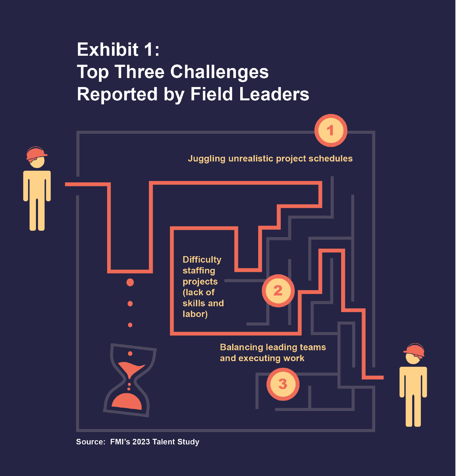
FMI’s recent talent research included feedback from more than 100 Field Leaders, Superintendents, and Project Managers, most of whom attended an FMI training program. These leaders reported their three greatest challenges (Exhibit 1):
- Juggling unrealistic project schedules,
- Difficulty staffing projects due to lack of skills and labor, and
- Balancing leading teams and executing work.
The first challenge is related to project schedules and the associated time to do the work. Project schedules in construction have become more and more compressed. FMI estimates that over the past 2 decades, from start of design to construction completion, the average schedule duration for a warehouse has been compressed by as much as 12 months.
The other two reported challenges are directly related to the availability of field talent and the time needed to develop skilled crew members. Labor shortages were the second-most cited cause for project delays in the 2022 Associated General Contractors of America/FMI Risk Survey, and according to the Bureau of Labor Statistics, the construction industry had only slightly more trade workers in July 2022 (7.7 million) than it had in January 2007 (7.6 million).
Furthermore, two-thirds of CEOs surveyed for FMI’s second quarter 2022 Construction Industry Round Table (CIRT) reported difficulties finding Field Managers. The shortfall predates the current environment and will continue to impact crews in the years to come.
It will take everyone in a company to address these difficulties, but it is almost certainly time to place a much higher priority on Field Leader training and development.
Companies need to help Field Leaders develop skills in four critical areas. These are:
- Leading and coordinating field crews,
- Planning weekly resource needs,
- Managing productivity, and
- Communicating effectively.
The difficult part is determining how to help your Field Leaders obtain the necessary skills to excel in these four tasks. Here are a few investments in your teams that will pay large dividends.
Make Time for Training and Development in the Field
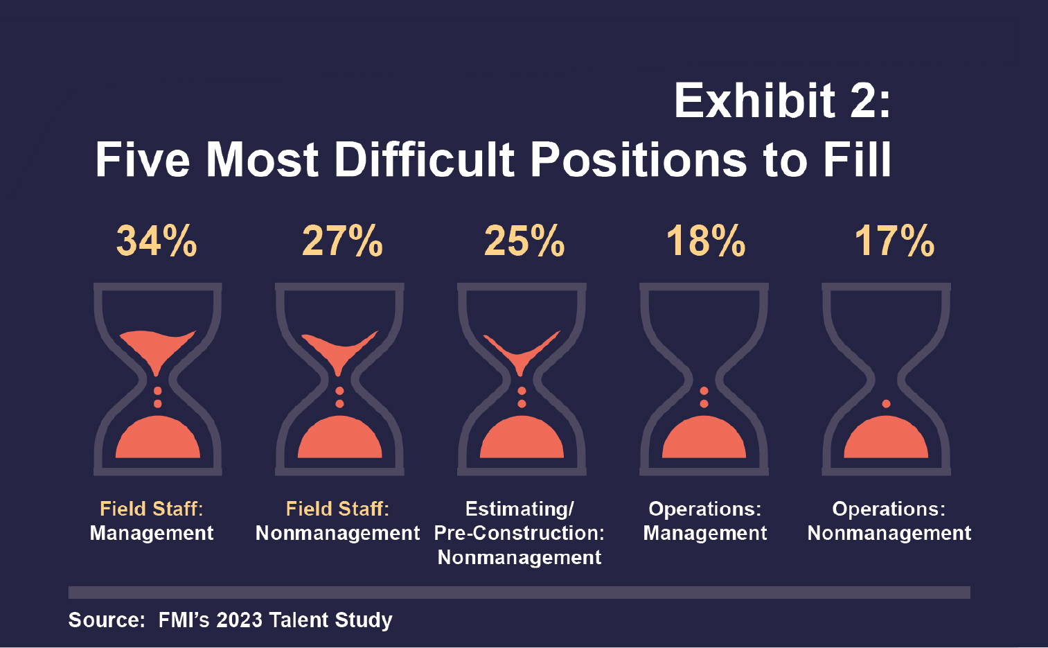
Many current leaders are in their third or fourth decade in the construction industry, and their experience is what generates success on their projects and in your company. These experienced Field Leaders are able to plan and execute jobs on compressed time frames, while also leaving time for newer workers to ask questions, challenge approaches, take ownership of results, and correct their errors. Qualified mentors are vital, in short supply, and operating under massive time constraints (see Exhibit 2).
“Everybody eventually is going to come across something that they’ve never had to do before,” says Seth Beckman, a Project Manager at Carlton Electric, Inc. “And the only thing you can do is get a hold of a person who has done it before and find out what was successful and anything that you really need to avoid in that situation.”
That depth of experience is not built overnight, and it requires a combination of skills. Do it incorrectly, and you risk Field Manager burnout. FMI’s Project Manager Academy research has found that overwork and a lack of skills training and career support are primary culprits.
“We have to look and find people who have the knowledge and the ability to lead and understand the work that we’re doing at the same time,” says Stanley Lee, Regional Manager at Gregori Construction, Inc.
Give your Field Leaders time to train and develop their teams. It is unrealistic to expect that a skilled trade workforce will be built without dedicating time for training and tapping your most experienced Field Leaders to conduct training and share their knowledge and experiences. Build it into project time lines and into your organization’s overall talent strategy, including roles, responsibilities, and expectations.
Focus on Planning and Resource-Related Delays
Think of a day on your jobsite when you had a field crew that was waiting, standing around, or working on less productive tasks for more than an hour. What was the cause for this situation?
The primary way to improve field productivity and reclaim time on your jobsites is by minimizing resource-related delays caused by not having the right materials, tools, equipment, or information in the hands of your Field Leaders at the time needed on the jobsite.
Field Leaders and organizations can minimize resource-related delays through planning. A strong pre-job planning process and weekly look-ahead procedures will identify those items that are needed by Field Leaders to help them be productive and provide time for teaching, training, and mentoring others, instead of responding to daily and weekly fire drills.
Weekly look-ahead plans should be developed by your Foremen or Superintendents, who identify critical tasks and activities planned for the next 2 or 3 weeks, including the manpower, material, tools, equipment, and information required to do the job. It is then the organization’s responsibility to ensure that the Field Leaders get what they need to install work correctly the first time.
It is imperative that you collaborate and engage with Foremen and Superintendents in planning the work both before the job starts and every week thereafter. They will build their planning muscles and, over time, will become better and better at recognizing what they need to be successful leading productive field crews. And providing your experienced Field Leaders with time to engage in training and development for themselves and others will be critical in this process.
Train Field Leaders in Communication Skills
Often, Field Leaders are technical experts who know how to build quality projects, but many lack soft skills, such as best practices around communication and how to motivate employees.
Your Field Leaders communicate with a broad range of project stakeholders, all of whom have different preferences and expectations for effective communication. Field Leaders direct work for your field crews, send and receive direction from Project Managers and owners, and coordinate with other Field Leaders and other trade contractors. These diverse groups often have different communication preferences, ranging from face to face to email, written job status reports, and text messages. They also have varying expectations for the level of detail they are given and when they are engaged in the process.
Teach your Field Leaders to listen to those with whom they interact and understand how to determine the best method for reaching them. Time management was cited as one of the top three challenges by Field Leaders surveyed, and communication failures underpin much of this stress. Understanding the best method for communicating and making decisions that will drive a project forward can help Field Leaders become more effective communicators and time managers.
Leverage Field Mentorship
Experienced Field Leaders make quick decisions to maximize productivity and efficiency, but getting those with fewer years on the job the same level of expertise takes time and attention. One way to quickly help newer Field Leaders is by formally pairing them with a mentor.
Having someone who can quickly answer questions and offer advice helps Field Leaders develop the necessary experience and confidence in their decisions. Formal mentoring arrangements enable knowledge transfer and—as they gain proficiency and experience ultimately allow more staff members to take ownership of projects. Mentoring also can serve as a crucial part of succession planning at different levels.
However, the lack of formal training programs in the past means that senior leaders may not be skilled at teaching inexperienced workers. This can be addressed with leadership training for those with valuable job knowledge, and ongoing skills training as people progress in the field.
How to Help Your Field Staff Succeed
A Field Leader’s job is complicated and challenging. Prioritize time for Field Leader training by minimizing resource-related delays on the jobsite. Focus on soft skills and communication, and leverage mentors to grow new, world-class Field Leaders.
Companies that invest in Field Leaders can lower business risk by building a deep pipeline of strong talent, enhance their ability to execute on projects, increase employee engagement and organizational loyalty, and improve Field Leaders’ ability to take on greater responsibility. Now is the time to act and build your leaders of the future.
FMI is a leading consulting and investment banking firm dedicated to serving companies working within the built environment. Its professionals are industry insiders who understand a company’s operating environment, challenges, and opportunities. FMI’s sector expertise and broad range of solutions help its clients discover value drivers, build resilient teams, streamline operations, grow with confidence, and sell with optimal results. Reprinted with permission from FMI. For more information, visit www.fmicorp.com.