Introduction
An Environmental Product Declaration, or EPD, is a third party–verified document about a product’s environmental impacts at different points in its life cycle. The creation of an EPD requires the manufacturer and those involved in the production and distribution of the product to determine and disclose detailed information about the materials, power, water, and other resources used at each part of the creation, use, and disposal of the product. For those manufacturers that complete the EPD journey for their products, the benefits are strong—both for them and for the specifiers and designers looking to use the products in their building designs.
Numerous benefits can be found in the use of EPDs for companies in the value chain for a building project, depending on the subject or level of information necessary to perform their work. This article focuses on three of the broad benefits of EPDs: 1) the information contained within an EPD is trustworthy, 2) an EPD provides environmental impact details that help increase sustainability for both manufacturers and specifiers, and 3) achievement of whole-building calculations and certifications are made easier by
using EPDs.
Trustworthy Information
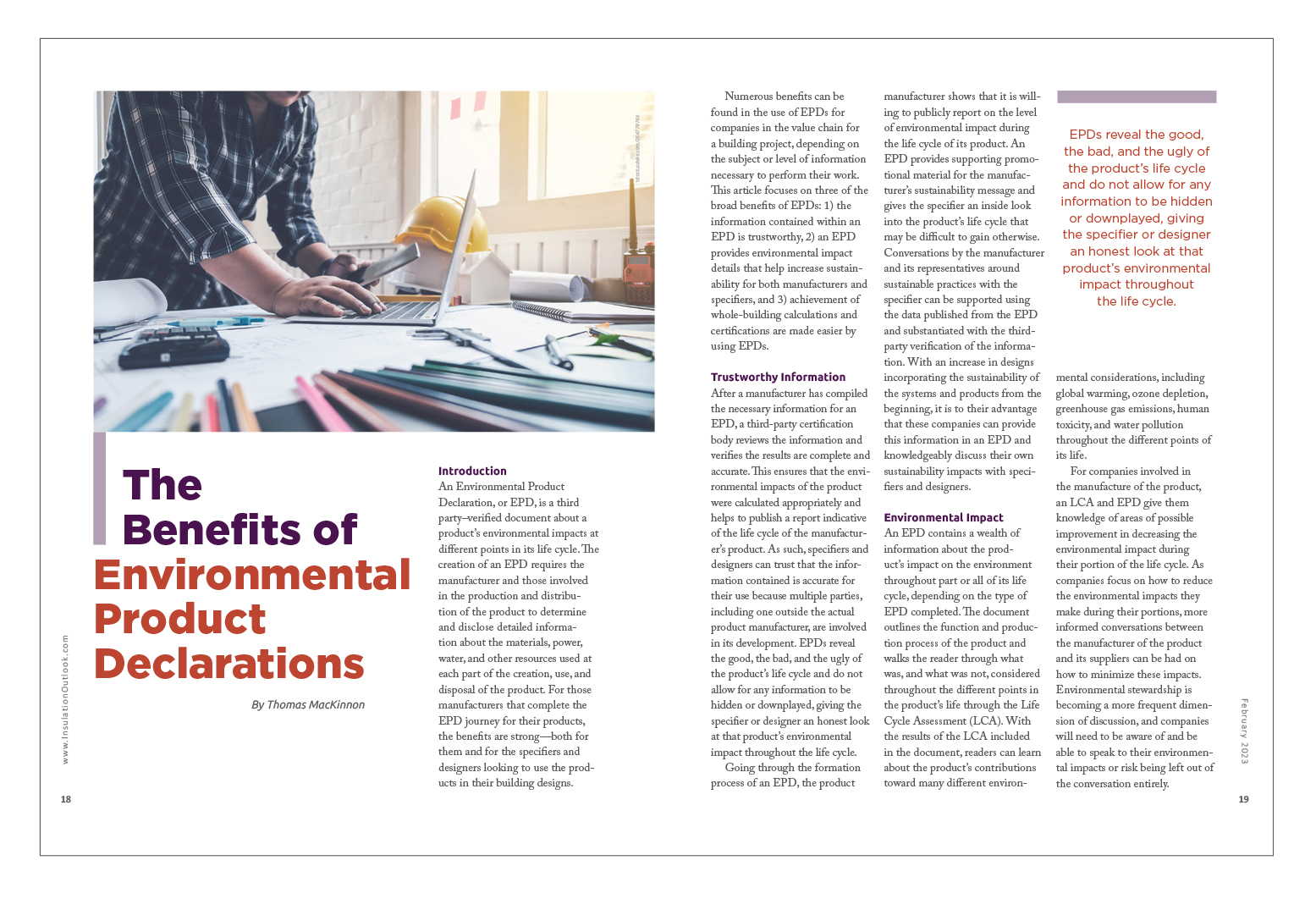
After a manufacturer has compiled the necessary information for an EPD, a third-party certification body reviews the information and verifies the results are complete and accurate. This ensures that the environmental impacts of the product were calculated appropriately and helps to publish a report indicative of the life cycle of the manufacturer’s product. As such, specifiers and designers can trust that the information contained is accurate for their use because multiple parties, including one outside the actual product manufacturer, are involved in its development. EPDs reveal the good, the bad, and the ugly of the product’s life cycle and do not allow for any information to be hidden or downplayed, giving the specifier or designer an honest look at that product’s environmental impact throughout the life cycle.
Going through the formation process of an EPD, the product manufacturer shows that it is willing to publicly report on the level of environmental impact during the life cycle of its product. An EPD provides supporting promotional material for the manufacturer’s sustainability message and gives the specifier an inside look into the product’s life cycle that may be difficult to gain otherwise. Conversations by the manufacturer and its representatives around sustainable practices with the specifier can be supported using the data published from the EPD and substantiated with the third-party verification of the information. With an increase in designs incorporating the sustainability of the systems and products from the beginning, it is to their advantage that these companies can provide this information in an EPD and knowledgeably discuss their own sustainability impacts with specifiers and designers.
Environmental Impact
An EPD contains a wealth of information about the product’s impact on the environment throughout part or all of its life cycle, depending on the type of EPD completed. The document outlines the function and production process of the product and walks the reader through what was, and what was not, considered throughout the different points in the product’s life through the Life Cycle Assessment (LCA). With the results of the LCA included in the document, readers can learn about the product’s contributions toward many different environmental considerations, including global warming, ozone depletion, greenhouse gas emissions, human toxicity, and water pollution throughout the different points of its life.
For companies involved in the manufacture of the product, an LCA and EPD give them knowledge of areas of possible improvement in decreasing the environmental impact during their portion of the life cycle. As companies focus on how to reduce the environmental impacts they make during their portions, more informed conversations between the manufacturer of the product and its suppliers can be had on how to minimize these impacts. Environmental stewardship is becoming a more frequent dimension of discussion, and companies will need to be aware of and be able to speak to their environmental impacts or risk being left out of the conversation entirely.
For specifiers and designers, the EPD gives them knowledge of the impacts their product choices make not only during their portion of the building development but before the product is delivered to the job site and after the building’s use as well. Specifications can be written with sustainability in mind, and with the understanding that the products selected not only meet the required technical attributes and standards required but also will minimize the hazards to the environment, both at the building site and far from it. Specifiers and designers can promote the sustainability of their designs to their clients and use the information gained from EPDs to have stronger conversations about the environmental impacts of their clients’ projects. This, in turn, makes calculation of the whole building’s sustainability easier and can lead to more sustainable design choices for each part of the project much earlier in the process, especially if that project is looking to achieve certification in a green building scheme.
Usable in Green Building Schemes and Evaluation of Building Sustainability
The information provided by an EPD does not stop at the product level, and it is a vital tool in the assessment of a building’s overall sustainability. As more and more jurisdictions implement sustainability initiatives and mandates, understanding the whole building’s impact on the environment is crucial to meeting the requirements, and products with EPDs will be sought out to supply this information. With many different products and systems running throughout the building, calculation of a building’s sustainability is a difficult task, but one that can be made easier with the information provided by EPDs.
Numerous calculators have been created to help designers with this task, with many certification bodies and environmental interest groups providing their own tools to determine the overall sustainability of a building. Common across each of these calculators is the need for precise input data so that the information calculated is as accurate as possible and can be used with confidence as part of the project’s design. As such, products with EPDs are sought out by the organizations behind the development of these calculators, because using EPD data, rather than generic product data, allows the calculators to arrive at an estimation much closer to the actual sustainability attributes of the building. Manufacturers who can provide this EPD data have the inside track on being promoted by these groups through their calculators and are more easily specified on the associated projects because their products are being used in the design calculations for the building’s overall sustainability.
Not surprisingly, material transparency is a focal point in green building, and the project designs that use products with EPDs are rewarded as they move toward certification. For example, the U.S. Green Building Council’s LEED v4.1 program, in the Building Design and Construction certification type, offers the Materials and Resources Credit “Environmental Product Declarations,” awarding up to two points when project teams select products with verified information on their environmental life-cycle impact.1 The Green Building Initiative rewards up to 39 points in the Product Life Cycle section of its Green Globes for New Construction system for using products with third-party verification/certification of the impacts throughout the product’s life cycle, such as EPDs.2 With the amount of environmental information EPDs provide, using products with EPDs is one of the most straightforward ways for a project team to help meet the requirements to achieve credits in a green building program for their building. Therefore, companies that can provide products that have an associated EPD are considered first for green building projects and are placed in an advantaged position within the design of these buildings.
Conclusion
EPDs provide numerous benefits for all members of the project chain. For specifiers and designers, an EPD represents a trustworthy, third party–verified collection of the environmental impacts the product makes before, during, and after its use as part of their project, giving a full-picture view of how their product choices affect the environment. Using an EPD makes whole-building sustainability calculations easier and more accurate than a generic counterpart and helps the project team meet the requirements for credit in green building project designs. For product manufacturers and the associated supply chain, EPDs provide the information necessary to lower their environmental impact throughout the chain and signal a commitment to a higher sustainability mission. These companies can add an environmental focus to their conversations with their suppliers, armed with the information gained by completing the EPD process for their product. On the marketability side, companies that can provide EPDs and the associated material transparency are able to provide the additional information on the project that specifiers and designers are looking for, giving them an edge in the project design.
As building owners continue to demand increases in the sustainability of building designs, the importance of EPDs and the information on the product life cycle they provide will continue to grow for all participants.
References
1. https://www.usgbc.org/leed/v41
2. https://thegbi.org/green-globes-certification/how-to-certify/new-construction/